2011 INFINITI QX56 ground
[x] Cancel search: groundPage 2960 of 5598
FSU-18
< REMOVAL AND INSTALLATION >
UPPER LINK
INSTALLATION
Note the following, and install in the reverse order of removal.
Perform final tightening of bolts and nuts at the vehicle installation position (rubber bushing), under unladenconditions with tires on level ground.
Perform inspection after installation. Refer to FSU-18, "
Inspection".
InspectionINFOID:0000000006225651
INSPECTION AFTER REMOVAL
Appearance
Check the following items, and replace the part if necessary.
Upper link and bushing for deformation, cracks or damage.
Ball joint boot for cracks or other damage, and also for grease leakage.
Ball Joint Inspection
Manually move ball stud to confirm it moves smoothly with no binding.
Swing Torque Inspection
1. Move the ball joint at least ten times by hand to check for smooth movement.
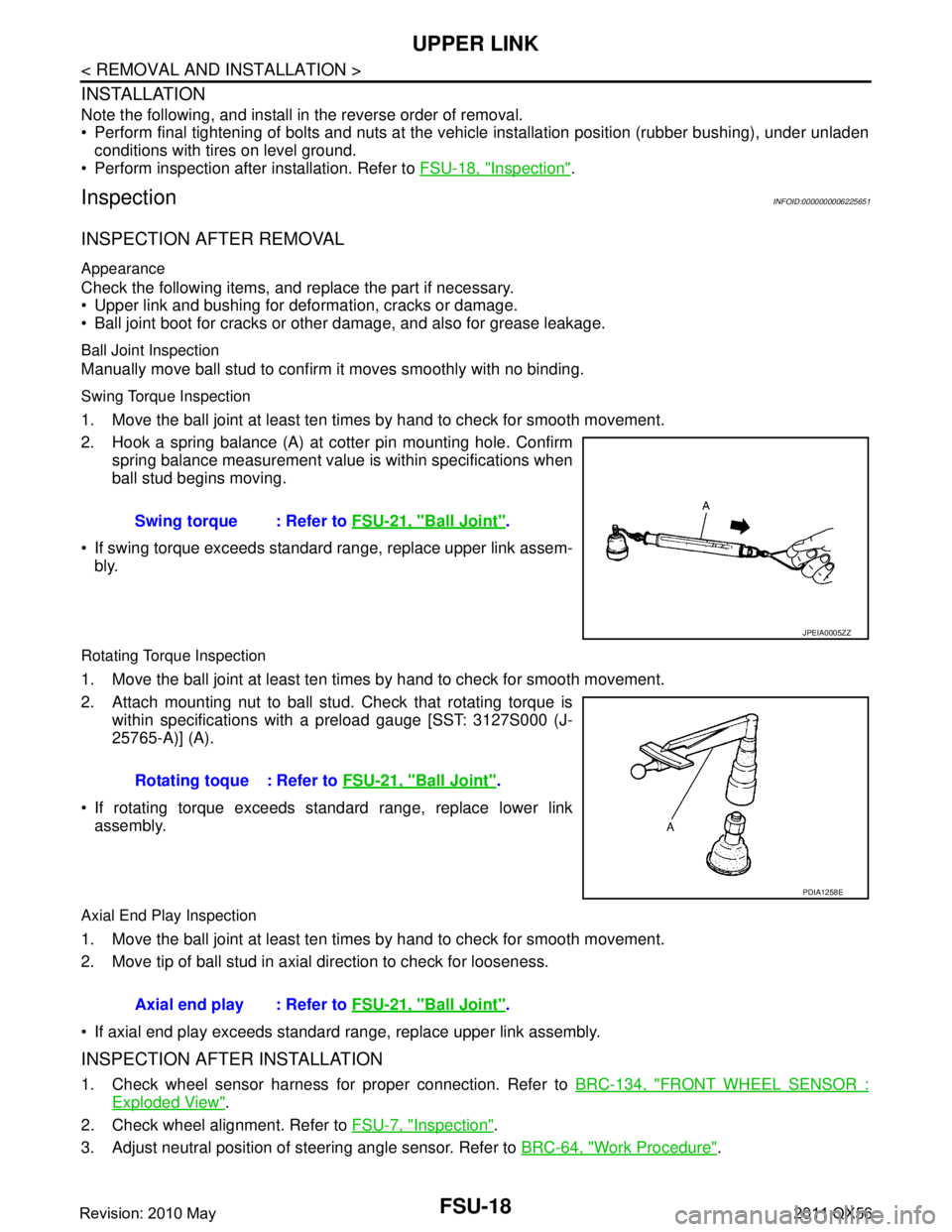
2. Hook a spring balance (A) at cotter pin mounting hole. Confirm
spring balance measurement value is within specifications when
ball stud begins moving.
If swing torque exceeds standard range, replace upper link assem- bly.
Rotating Torque Inspection
1. Move the ball joint at least ten times by hand to check for smooth movement.
2. Attach mounting nut to ball stud. Check that rotating torque is
within specifications with a preload gauge [SST: 3127S000 (J-
25765-A)] (A).
If rotating torque exceeds standard range, replace lower link assembly.
Axial End Play Inspection
1. Move the ball joint at least ten times by hand to check for smooth movement.
2. Move tip of ball stud in axial direction to check for looseness.
If axial end play exceeds standard range, replace upper link assembly.
INSPECTION AFTER INSTALLATION
1. Check wheel sensor harness for proper connection. Refer to BRC-134, "FRONT WHEEL SENSOR :
Exploded View".
2. Check wheel alignment. Refer to FSU-7, "
Inspection".
3. Adjust neutral position of steering angle sensor. Refer to BRC-64, "
Work Procedure".
Swing torque : Refer to
FSU-21, "
Ball Joint".
JPEIA0005ZZ
Rotating toque : Refer to FSU-21, "Ball Joint".
PDIA1258E
Axial end play : Refer to FSU-21, "Ball Joint".
Revision: 2010 May2011 QX56
Page 2975 of 5598
HOW TO READ WIRING DIAGRAMSGI-11
< HOW TO USE THIS MANUAL >
C
DE
F
G H
I
J
K L
M B
GI
N
O P
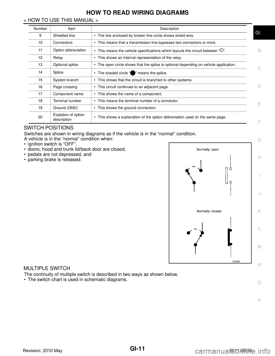
SWITCH POSITIONS
Switches are shown in wiring diagrams as if the vehicle is in the “normal” condition.
A vehicle is in the “normal” condition when:
ignition switch is “OFF”,
doors, hood and trunk lid/back door are closed,
pedals are not depressed, and
parking brake is released.
MULTIPLE SWITCH
The continuity of multiple switch is described in two ways as shown below.
The switch chart is used in schematic diagrams.
9 Shielded line The line enclosed by broken line circle shows shield wire.
10 Connectors This means that a transmission line bypasses two connectors or more.
11 Option abbreviation This means the vehicle specifications which layouts the circuit between “ ”.
12 Relay This shows an internal representation of the relay.
13 Optional splice The open circle shows that the splice is optional depending on vehicle application.
14 Splice The shaded circle “ ” means the splice.
15 System branch This shows that the circuit is branched to other systems.
16 Page crossing This circuit continues to an adjacent page.
17 Component name This shows the name of a component.
18 Terminal number This means the terminal number of a connector.
19 Ground (GND) This shows the ground connection.
20 Explation of option
description This shows a explanation of the option abbreviation used on the same page.
Number Item Description
SGI860
Revision: 2010 May2011 QX56
Page 2979 of 5598

ABBREVIATIONSGI-15
< HOW TO USE THIS MANUAL >
C
DE
F
G H
I
J
K L
M B
GI
N
O P
E
F
G
H
ABBREVIATION DESCRIPTION E/T Exhaust temperature
EBD Electric brake force distribution EC Engine control
ECL Engine coolant level
ECM Engine control module ECT Engine coolant temperature
ECV Electrical control valve
EEPROM Electrically erasable programmable read only memory EFT Engine fuel temperature
EGR Exhaust gas recirculation
EGRT Exhaust gas recirculation temperature EGT Exhaust gas temperature
EOP Engine oil pressure EP Exhaust pressure
EPR Exhaust pressure regulator EPS Electronically controlled power steering
ESP Electronic stability program system
EVAP canister Evaporative emission canister EXC Exhaust control
ABBREVIATION DESCRIPTION FC Fan control
FCW Forward collision warning FIC Fuel injector controlFP Fuel pump
FR Front
FRP Fuel rail pressure FRT Fuel rail temperature
FTP Fuel tank pressure FTT Fuel tank temperature
ABBREVIATION DESCRIPTION GND GroundGPS Global positioning systemGST Generic scan tool
ABBREVIATION DESCRIPTION HBMC Hydraulic body-motion control systemHDD Hard disk drive
HO2S Heated oxygen sensor HOC Heated oxidation catalyst
Revision: 2010 May2011 QX56
Page 2995 of 5598
PRECAUTIONSGI-31
< PRECAUTION >
C
DE
F
G H
I
J
K L
M B
GI
N
O P
Dispose of used oil and used oil filters through authorized waste disposal contractors to licensed waste dis-
posal sites, or to the waste oil reclamation trade. If in doubt, contact the local authority for advice on disposal
facilities.
It is illegal to pour used oil on to the ground, dow n sewers or drains, or into water sources.
The regulations concerning po llution vary between regions.
Air ConditioningINFOID:0000000006280875
Use an approved refrigerant recovery unit any time t he air conditioning system must be discharged. Refer to
HA section “REFRIGERANT” fo r specific instructions.
FuelINFOID:0000000006280876
INFINITI recommends the use of unleaded premium gasoli ne with an octane rating of at least 91 AKI (Anti-
Knock Index) number (Research octane number 96).
If unleaded premium gasoline is not available, unleaded r egular gasoline with an octane rating of at least 87
AKI number (Research octane number 91), can be used. In such case, engine performance may be decrease.
CAUTION:
Using a fuel other than that specified could ad versely affect the emission control system, and may
also affect warranty coverage.
Under no circumstances should a leaded gasoline be used, because this will damage the three-way
catalyst.
Do not use E-85 fuel in the vehicle . The vehicle is not designed to run on E-85 fuel. Using E-85 fuel
can damage the fuel system components and is not covered by the INFINITI vehicle limited warranty.
Revision: 2010 May2011 QX56
Page 2996 of 5598
GI-32
< PRECAUTION >
LIFTING POINT
LIFTING POINT
Pantograph JackINFOID:0000000006280877
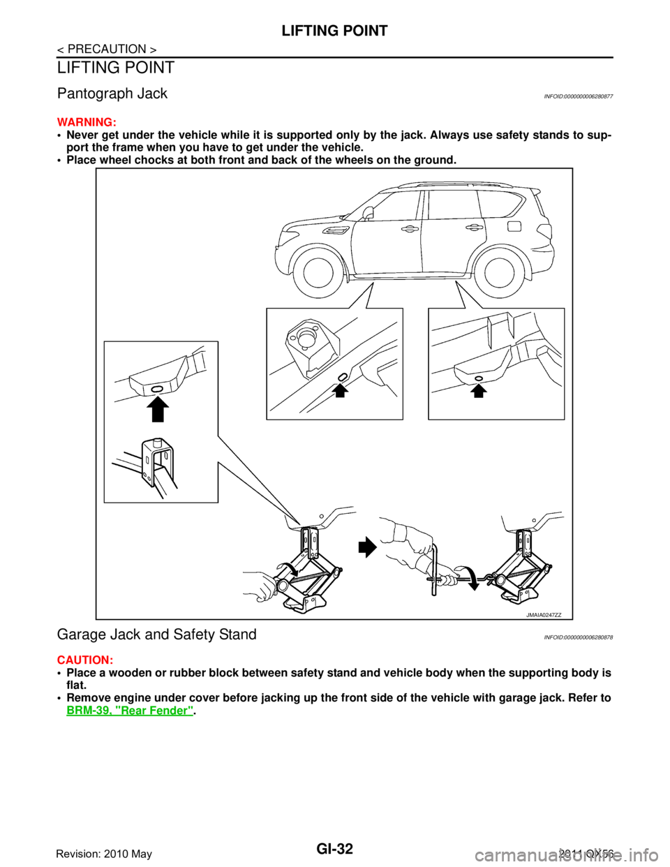
WARNING:
Never get under the vehicle while it is supported only by the jack. Always use safety stands to sup-
port the frame when you have to get under the vehicle.
Place wheel chocks at both front an d back of the wheels on the ground.
Garage Jack and Safety StandINFOID:0000000006280878
CAUTION:
Place a wooden or rubber block between safety stan d and vehicle body when the supporting body is
flat.
Remove engine under cover before jacking up the front side of the vehicle with garage jack. Refer to
BRM-39, "
Rear Fender".
JMAIA0247ZZ
Revision: 2010 May2011 QX56
Page 2998 of 5598
GI-34
< PRECAUTION >
TOW TRUCK TOWING
TOW TRUCK TOWING
Tow Truck TowingINFOID:0000000006280880
CAUTION:
All applicable local laws regarding the towing operation must be obeyed.
It is necessary to use proper towi ng equipment to avoid possible damage to the vehicle during tow-
ing operation. To wing is in accordance with Towing Procedure Manual at dealer.
Always attach safety chains before towing.
When towing, check that the transmission, steering syst em and powertrain are in good order. If any
unit is damaged, dollies must be used.
Never tow automatic transmission model from the rear (that is backward) with four wheels on the
ground. This may cause serious and exp ensive damage to the transmission.
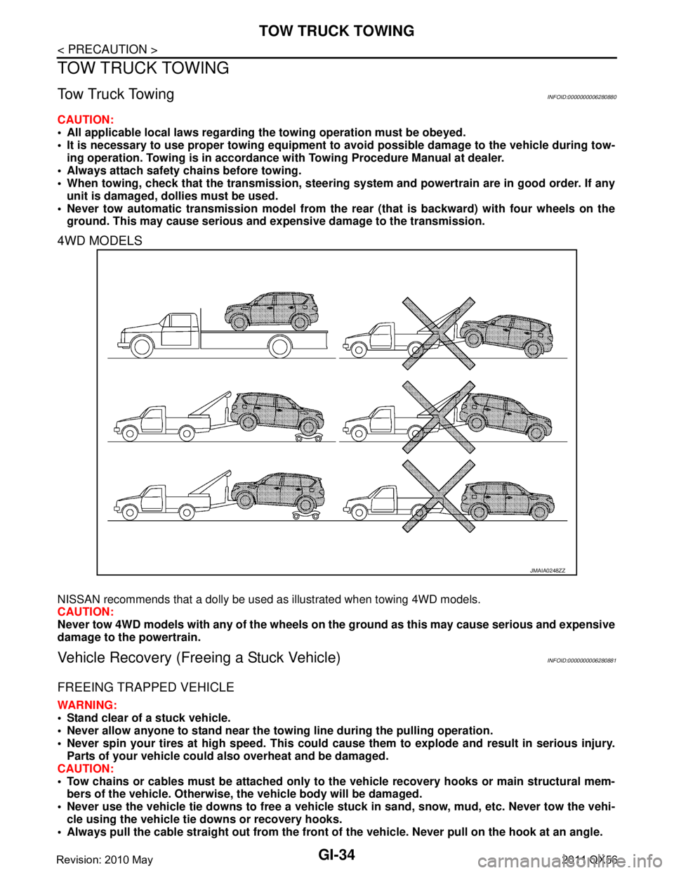
4WD MODELS
NISSAN recommends that a dolly be used as illustrated when towing 4WD models.
CAUTION:
Never tow 4WD models with any of the wheels on the ground as this may cause serious and expensive
damage to the powertrain.
Vehicle Recovery (Freeing a Stuck Vehicle)INFOID:0000000006280881
FREEING TRAPPED VEHICLE
WARNING:
Stand clear of a stuck vehicle.
Never allow anyone to stand near the towing line during the pulling operation.
Never spin your tires at high sp eed. This could cause them to explode and result in serious injury.
Parts of your vehicle could also overheat and be damaged.
CAUTION:
Tow chains or cables must be attached only to the vehicle recovery hooks or main structural mem-
bers of the vehicle. Otherwise, the vehicle body will be damaged.
Never use the vehicle tie downs to free a vehicle st uck in sand, snow, mud, etc. Never tow the vehi-
cle using the vehicle tie downs or recovery hooks.
Always pull the cable straight out from the front of the vehicle. Never pull on the hook at an angle.
JMAIA0248ZZ
Revision: 2010 May2011 QX56
Page 3005 of 5598
SERVICE INFORMATION FOR ELECTRICAL INCIDENTGI-41
< BASIC INSPECTION >
C
DE
F
G H
I
J
K L
M B
GI
N
O P
lowing section illustrates ways to simulate the c onditions/environment under which the owner experiences an
electrical incident.
The section is broken into the six following topics: Vehicle vibration
Heat sensitive
Freezing
Water intrusion
Electrical load
Cold or hot start up
Get a thorough description of the incident from the customer . It is important for simulating the conditions of the
problem.
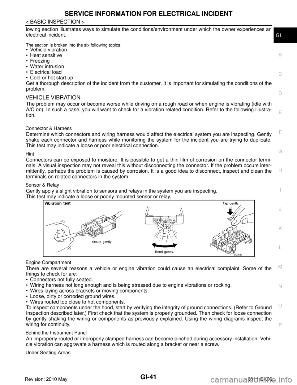
VEHICLE VIBRATION
The problem may occur or become worse while driving on a rough road or when engine is vibrating (idle with
A/C on). In such a case, you will want to check for a vibration related condition. Refer to the following illustra-
tion.
Connector & Harness
Determine which connectors and wiring harness would affect the electrical system you are inspecting. Gently
shake each connector and harness while monitoring the syst em for the incident you are trying to duplicate.
This test may indicate a loose or poor electrical connection.
Hint
Connectors can be exposed to moisture. It is possible to get a thin film of corrosion on the connector termi-
nals. A visual inspection may not reveal this without disconnecting the connector. If the problem occurs inter-
mittently, perhaps the problem is caused by corrosi on. It is a good idea to disconnect, inspect and clean the
terminals on related connectors in the system.
Sensor & Relay
Gently apply a slight vibration to sensors and relays in the system you are inspecting.
This test may indicate a loose or poorly mounted sensor or relay.
Engine Compartment
There are several reasons a vehicle or engine vibration could cause an electrical complaint. Some of the
things to check for are:
Connectors not fully seated.
Wiring harness not long enough and is being stressed due to engine vibrations or rocking.
Wires laying across brackets or moving components.
Loose, dirty or corroded ground wires.
Wires routed too close to hot components.
To inspect components under the hood, start by verifyi ng the integrity of ground connections. (Refer to Ground
Inspection described later.) First check that the syst em is properly grounded. Then check for loose connection
by gently shaking the wiring or components as previous ly explained. Using the wiring diagrams inspect the
wiring for continuity.
Behind the Instrument Panel
An improperly routed or improperly clamped harness can become pinched during accessory installation. Vehi-
cle vibration can aggravate a harness which is routed along a bracket or near a screw.
Under Seating Areas
SGI839
Revision: 2010 May2011 QX56
Page 3007 of 5598
SERVICE INFORMATION FOR ELECTRICAL INCIDENTGI-43
< BASIC INSPECTION >
C
DE
F
G H
I
J
K L
M B
GI
N
O P
Circuit InspectionINFOID:0000000006280855
DESCRIPTION
In general, testing electrical circuits is an easy task if it is approached in a logical and organized method. Before beginning it is important to have all available information on the system to be tested. Also, get a thor-
ough understanding of system operation. Then you will be able to use the appropriate equipment and follow
the correct test procedure.
You may have to simulate vehicle vibrations while te sting electrical components. Gently shake the wiring
harness or electrical component to do this.
NOTE:
Refer to GI-37, "
How to Check Terminal" to probe or check terminal.
TESTING FOR “OPENS” IN THE CIRCUIT
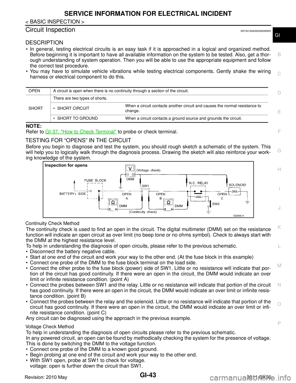
Before you begin to diagnose and test the system, you should rough sketch a schematic of the system. This
will help you to logically walk through the diagnosis process. Drawing the sketch will also reinforce your work-
ing knowledge of the system.
Continuity Check Method
The continuity check is used to find an open in the circui t. The digital multimeter (DMM) set on the resistance
function will indicate an open circuit as over limit (no beep tone or no ohms symbol). Check to always start with
the DMM at the highest resistance level.
To help in understanding the diagnosis of open circui ts, please refer to the previous schematic.
Disconnect the battery negative cable.
Start at one end of the circuit and work your way to the other end. (At the fuse block in this example)
Connect one probe of the DMM to the fuse block terminal on the load side.
Connect the other probe to the fuse block (power) side of SW1. Little or no resistance will indicate that por-
tion of the circuit has good continuity. If there were an open in the circuit, the DMM would indicate an over
limit or infinite resistance condition. (point A)
Connect the probes between SW1 and the relay. Little or no resistance will indicate that portion of the circuit
has good continuity. If there were an open in the circuit, t he DMM would indicate an over limit or infinite resis-
tance condition. (point B)
Connect the probes between the relay and the solenoid. Little or no resistance will indicate that portion of the
circuit has good continuity. If there were an open in the ci rcuit, the DMM would indicate an over limit or infi-
nite resistance condition. (point C)
Any circuit can be diagnosed using the approach in the previous example.
Voltage Check Method
To help in understanding the diagnosis of open circui ts please refer to the previous schematic.
In any powered circuit, an open can be found by methodica lly checking the system for the presence of voltage.
This is done by switching the DMM to the voltage function.
Connect one probe of the DMM to a known good ground.
Begin probing at one end of the circuit and work your way to the other end.
With SW1 open, probe at SW1 to check for voltage. voltage: open is further down the circuit than SW1.
OPEN A circuit is open when there is no continuity through a section of the circuit.
SHORT There are two types of shorts.
SHORT CIRCUIT
When a circuit contacts another circuit and causes the normal resistance to
change.
SHORT TO GROUND When a circuit contacts a ground source and grounds the circuit.
SGI846-A
Revision: 2010 May2011 QX56