Page 2794 of 5598
![INFINITI QX56 2011 Factory Service Manual
EXL-84
< DTC/CIRCUIT DIAGNOSIS >[XENON TYPE]
POWER SUPPLY AND GROUND CIRCUIT
POWER SUPPLY AND GROUND CIRCUIT
AFS CONTROL UNIT
AFS CONTROL UNIT : Diagnosis ProcedureINFOID:0000000006213953
1.FUSE INSP INFINITI QX56 2011 Factory Service Manual
EXL-84
< DTC/CIRCUIT DIAGNOSIS >[XENON TYPE]
POWER SUPPLY AND GROUND CIRCUIT
POWER SUPPLY AND GROUND CIRCUIT
AFS CONTROL UNIT
AFS CONTROL UNIT : Diagnosis ProcedureINFOID:0000000006213953
1.FUSE INSP](/manual-img/42/57033/w960_57033-2793.png)
EXL-84
< DTC/CIRCUIT DIAGNOSIS >[XENON TYPE]
POWER SUPPLY AND GROUND CIRCUIT
POWER SUPPLY AND GROUND CIRCUIT
AFS CONTROL UNIT
AFS CONTROL UNIT : Diagnosis ProcedureINFOID:0000000006213953
1.FUSE INSPECTION
Check that the following fuses are not fusing.
Is the inspection result normal?
YES >> GO TO 2.
NO >> Repair the applicable circuit. And then replace the fuse.
2.CHECK POWER SUPPLY CIRCUIT
1. Turn ignition switch OFF.
2. Disconnect AFS control unit harness connector.
3. Turn ignition switch ON.
4. Check voltage between AFS control unit harness connector and ground.
Is the inspection result normal?
YES >> GO TO 3.
NO >> Repair harness or connector.
3.CHECK GROUND CIRCUIT
1. Turn ignition switch OFF.
2. Check continuity between AFS control unit harness connectors and ground.
Is the inspection result normal?
YES >> Power supply and ground circuit are normal.
NO >> Repair harness or connector.
Signal name Connection position Fuse No. Capacity
Ignition power supply FUSE BLOCK (J/B) 3 10 A
(+)
(− ) Voltag e
(Approx.)
AFS control unit
Connector Terminal M135 1 Ground Battery voltage
AFS control unit GroundContinuity
Connector Terminal
M135 25 Existed
Revision: 2010 May2011 QX56
Page 2817 of 5598
![INFINITI QX56 2011 Factory Service Manual
AFS SWITCHEXL-107
< DTC/CIRCUIT DIAGNOSIS > [XENON TYPE]
C
D
E
F
G H
I
J
K
M A
B
EXL
N
O P
AFS SWITCH
Component Function CheckINFOID:0000000006213973
1.CHECK AFS SWITCH SIGNAL BY CONSULT-III
CONSULT- INFINITI QX56 2011 Factory Service Manual
AFS SWITCHEXL-107
< DTC/CIRCUIT DIAGNOSIS > [XENON TYPE]
C
D
E
F
G H
I
J
K
M A
B
EXL
N
O P
AFS SWITCH
Component Function CheckINFOID:0000000006213973
1.CHECK AFS SWITCH SIGNAL BY CONSULT-III
CONSULT-](/manual-img/42/57033/w960_57033-2816.png)
AFS SWITCHEXL-107
< DTC/CIRCUIT DIAGNOSIS > [XENON TYPE]
C
D
E
F
G H
I
J
K
M A
B
EXL
N
O P
AFS SWITCH
Component Function CheckINFOID:0000000006213973
1.CHECK AFS SWITCH SIGNAL BY CONSULT-III
CONSULT-III DATA MONITOR
1. Turn ignition switch ON.
2. Select “AFS SW” of ADAPTIVE LIGHT data monitor item.
3. With operating the AFS switch , check the monitor status.
Is the inspection result normal?
YES >> AFS switch circuit is normal.
NO >> Refer to EXL-107, "
Diagnosis Procedure".
Diagnosis ProcedureINFOID:0000000006213974
1.CHECK AFS SWITCH FUSE
1. Turn ignition switch OFF.
2. Check that the following fuses is not fusing.
Is the inspection result normal?
YES >> GO TO 2.
NO >> Repair the applicable. And then replace the fuse.
2.CHECK POWER SUPPLY CIRCUIT
1. Disconnect triple switch connector.
2. Check voltage between triple switch harness connector and ground.
Is the inspection result normal?
YES >> GO TO 3.
NO >> Repair or replace harness.
3.CHECK AFS SWITCH CIRCUIT
1. Disconnect AFS control unit connector.
2. Check continuity between AFS control unit har ness connector and triple switch harness connector.
3. Check continuity between AFS control unit harness connector and ground.
Monitor item Condition Monitor status
AFS SW AFS switch ON On
OFF Off
Location Fuse No. Capacity
Fuse block (J/B) #3 10 A
(+) (–)Voltage (V)
(Approx.)
Triple switch
Connector Terminal M126 3 Ground Battery voltage
AFS control unit Triple switch Continuity
Connector Terminal Connector Terminal
M1353M1264Existed
AFS control unit GroundContinuity
Connector Terminal
M135 3 Not existed
Revision: 2010 May2011 QX56
Page 2819 of 5598
![INFINITI QX56 2011 Factory Service Manual
TAIL LAMP CIRCUITEXL-109
< DTC/CIRCUIT DIAGNOSIS > [XENON TYPE]
C
D
E
F
G H
I
J
K
M A
B
EXL
N
O P
TAIL LAMP CIRCUIT
BODY SIDE
BODY SIDE : Component Function CheckINFOID:0000000006213976
1.CHECK TAIL INFINITI QX56 2011 Factory Service Manual
TAIL LAMP CIRCUITEXL-109
< DTC/CIRCUIT DIAGNOSIS > [XENON TYPE]
C
D
E
F
G H
I
J
K
M A
B
EXL
N
O P
TAIL LAMP CIRCUIT
BODY SIDE
BODY SIDE : Component Function CheckINFOID:0000000006213976
1.CHECK TAIL](/manual-img/42/57033/w960_57033-2818.png)
TAIL LAMP CIRCUITEXL-109
< DTC/CIRCUIT DIAGNOSIS > [XENON TYPE]
C
D
E
F
G H
I
J
K
M A
B
EXL
N
O P
TAIL LAMP CIRCUIT
BODY SIDE
BODY SIDE : Component Function CheckINFOID:0000000006213976
1.CHECK TAIL LAMP OPERATION
CONSULT-III ACTIVE TEST
1. Select “EXTERNAL LAMPS” of IPDM E/R active test item.
2. With operating the test items, chec k that the tail lamp is turned ON.
Is the inspection result normal?
YES >> Tail lamp circuit is normal.
NO >> Refer to EXL-109, "
BODY SIDE : Diagnosis Procedure".
BODY SIDE : Diagnosis ProcedureINFOID:0000000006213977
1.CHECK TAIL LAMP FUSE
1. Turn ignition switch OFF.
2. Check that the following fuses are not fusing.
Is the inspection result normal?
YES >> GO TO 2.
NO >> Repair the malfunctioning part before replacing the fuse.
2.CHECK TAIL LAMP OUTPUT VOLTAGE
CONSULT-III ACTIVE TEST
1. Disconnect rear combination lamp connector.
2. Turn ignition switch ON.
3. Select “EXTERNAL LAMPS” of IPDM E/R active test item.
4. With operating the test items, check vo ltage between IPDM E/R harness connector and ground.
Is the inspection result normal?
YES >> GO TO 3.
NO >> GO TO 4.
3.CHECK TAIL LAMP OPEN CIRCUIT
1. Turn ignition switch OFF.
2. Disconnect the following connectors.
- IPDM E/R
- Front combination lamp
- Rear combination lamp TAIL : Tail Lamp ON
Off : Tail lamp OFF
Unit Location Fuse No. Capacity
Tail lamp IPDM E/R #46
10 A
#47
(+)
(− )Test item Vo l ta g e
(Approx.)
IPDM E/R
Connector Terminal
E14 38
GroundEXTERNAL
LAMPS TAIL Battery voltage
Off 0 V
44 TAIL Battery voltage
Off 0 V
Revision: 2010 May2011 QX56
Page 3924 of 5598

PG
COMPONENT PARTSPG-5
< SYSTEM DESCRIPTION >
C
DE
F
G H
I
J
K L
B A
O P
N
SYSTEM DESCRIPTION
COMPONENT PARTS
Circuit BreakerINFOID:0000000006275745
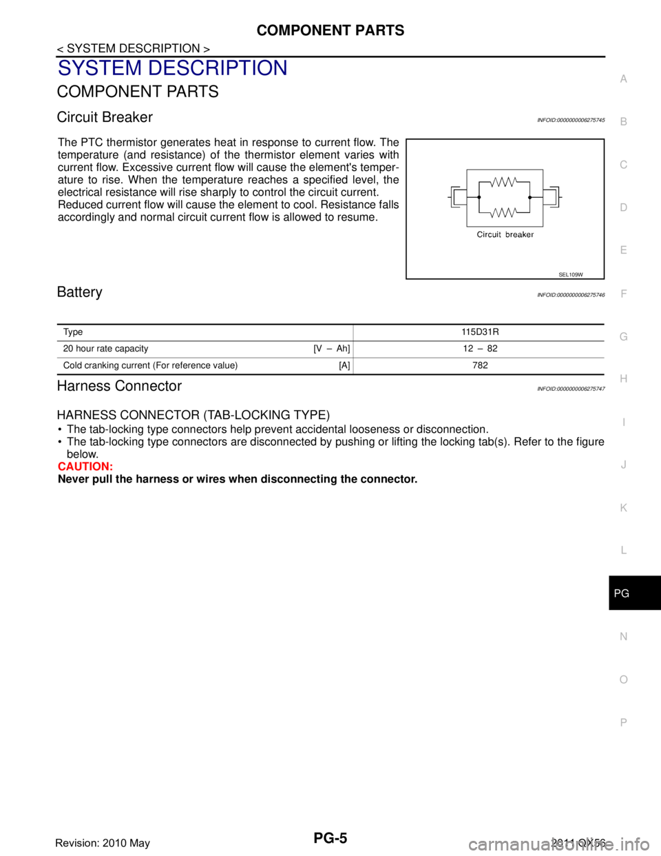
The PTC thermistor generates heat in response to current flow. The
temperature (and resistance) of t
he thermistor element varies with
current flow. Excessive current flow will cause the element's temper-
ature to rise. When the temperature reaches a specified level, the
electrical resistance will rise shar ply to control the circuit current.
Reduced current flow will cause the element to cool. Resistance falls
accordingly and normal circuit current flow is allowed to resume.
BatteryINFOID:0000000006275746
Harness ConnectorINFOID:0000000006275747
HARNESS CONNECTOR (TAB-LOCKING TYPE)
The tab-locking type connectors help prevent accidental looseness or disconnection.
The tab-locking type connectors are disconnected by pushi ng or lifting the locking tab(s). Refer to the figure
below.
CAUTION:
Never pull the harness or wires when disconnecting the connector.
SEL109W
Ty pe 115D31R
20 hour rate capacity [V – Ah] 12 – 82
Cold cranking current (For reference value) [A] 782
Revision: 2010 May2011 QX56
Page 4079 of 5598

PG-160
< BASIC INSPECTION >
BATTERY INSPECTION
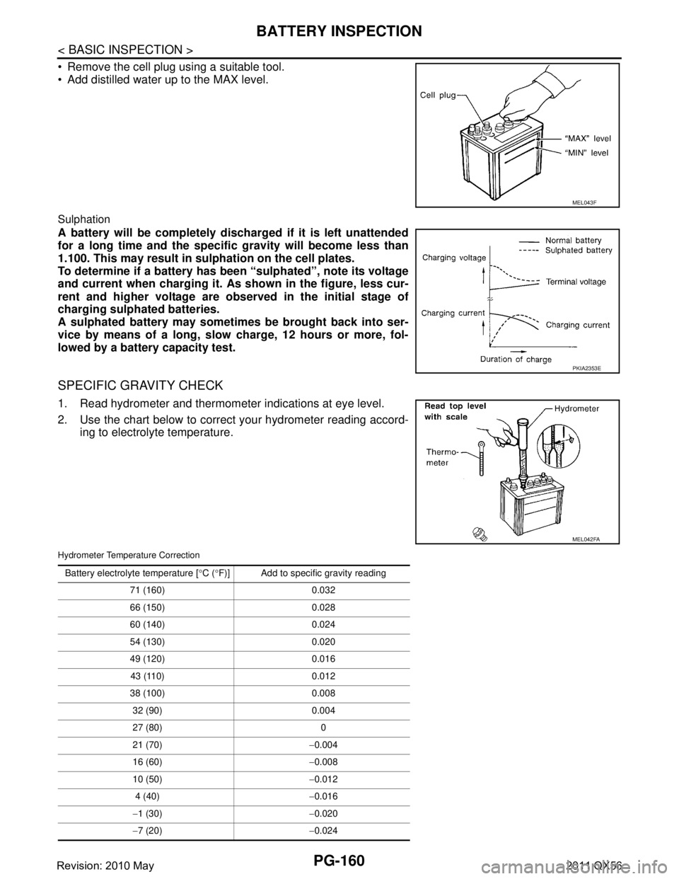
Remove the cell plug using a suitable tool.
Add distilled water up to the MAX level.
Sulphation
A battery will be completely discharged if it is left unattended
for a long time and the specific gravity will become less than
1.100. This may result in sulphation on the cell plates.
To determine if a battery has been “sulphated”, note its voltage
and current when charging it. As shown in the figure, less cur-
rent and higher voltage are observed in the initial stage of
charging sulphated batteries.
A sulphated battery may sometimes be brought back into ser-
vice by means of a long, slow charge, 12 hours or more, fol-
lowed by a battery capacity test.
SPECIFIC GRAVITY CHECK
1. Read hydrometer and thermometer indications at eye level.
2. Use the chart below to correct your hydrometer reading accord- ing to electrolyte temperature.
Hydrometer Temperature Correction
MEL043F
PKIA2353E
MEL042FA
Battery electrolyte temperature [ °C ( °F)] Add to specific gravity reading
71 (160) 0.032
66 (150) 0.028
60 (140) 0.024
54 (130) 0.020
49 (120) 0.016 43 (110) 0.012
38 (100) 0.008 32 (90) 0.004
27 (80) 0
21 (70) −0.004
16 (60) −0.008
10 (50) −0.012
4 (40) −0.016
− 1 (30) −0.020
− 7 (20) −0.024
Revision: 2010 May2011 QX56
Page 4085 of 5598
PG-166
< SERVICE DATA AND SPECIFICATIONS (SDS)
SERVICE DATA AND SPECIFICATIONS (SDS)
SERVICE DATA AND SPECIFICATIONS (SDS)
SERVICE DATA AND SPECIFICATIONS (SDS)
BatteryINFOID:0000000006275783
Ty p e11 5 D 3 1 R
20 hour rate capacity [V – Ah] 12 – 82
Cold cranking current (For reference value) [A] 782
Revision: 2010 May2011 QX56