2011 INFINITI QX56 airbag
[x] Cancel search: airbagPage 1 of 5598
A
B
D
E
F
G
H
I
J
K
L
M
N
P
O
C
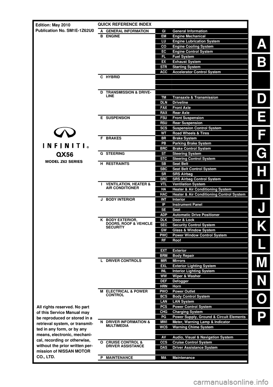
QUICK REFERENCE INDEX
AGENERAL INFORMATIONGIGeneral Information
BENGINEEMEngine Mechanical
LUEngine Lubrication System
COEngine Cooling System
ECEngine Control System
FLFuel System
EXExhaust System
STRStarting System
ACCAccelerator Control System
CHYBRIDHBCHybrid Control System
HBBHybrid Battery System
HBRHybrid Brake System
DTRANSMISSION & DRIVE-
LINECLClutch
TMTransaxle & Transmission
DLNDriveline
FAXFront Axle
RAXRear Axle
ESUSPENSIONFSUFront Suspension
RSURear Suspension
SCSSuspension Control System
WTRoad Wheels & Tires
FBRAKESBRBrake System
PBParking Brake System
BRCBrake Control System
GSTEERINGSTSteering System
STCSteering Control System
HRESTRAINTSSBSeat Belt
SBCSeat Belt Control System
SRSRS Airbag
SRCSRS Airbag Control System
IVENTILATION, HEATER &
AIR CONDITIONERVTLVentilation System
HAHeater & Air Conditioning System
HACHeater & Air Conditioning Control System
JBODY INTERIORINTInterior
IPInstrument Panel
SESeat
ADPAutomatic Drive Positioner
KBODY EXTERIOR,
DOORS, ROOF & VEHICLE
SECURITYDLKDoor & Lock
SECSecurity Control System
GWGlass & Window System
PWCPower Window Control System
RFRoof
HDHood
EXTExterior
BRMBody Repair
LDRIVER CONTROLSMIRMirrors
EXLExterior Lighting System
INLInterior Lighting System
WWWiper & Washer
DEFDefogger
HRNHorn
MELECTRICAL & POWER
CONTROLPWOPower Outlet
BCSBody Control System
LANLAN System
PCSPower Control System
CHGCharging System
PGPower Supply, Ground & Circuit Elements
NDRIVER INFORMATION &
MULTIMEDIAMWIMeter, Warning Lamp & Indicator
WCSWarning Chime System
SNSonar System
AVAudio, Visual & Navigation System
OCRUISE CONTROL &
DRIVER ASSISTANCECCSCruise Control System
DASDriver Assistance System
DMSDrive Mode System
PMAINTENANCEMAMaintenance
All rights reserved. No part
of this Service Manual may
be reproduced or stored in a
retrieval system, or transmit-
ted in any form, or by any
means, electronic, mechani-
cal, recording or otherwise,
without the prior written per-
mission of NISSAN MOTOR
CO., LTD.
Edition: May 2010
Publication No. SM1E-1Z62U0
Page 4764 of 5598

SR-1
RESTRAINTS
C
DE
F
G
I
J
K L
M
SECTION SR
A
B
SR
N
O P
CONTENTS
SRS AIRBAG
PRECAUTION ................ ...............................2
PRECAUTIONS .............................................. .....2
Precaution for Supplemental Restraint System
(SRS) "AIR BAG" and "SEAT BELT PRE-TEN-
SIONER" ............................................................. ......
2
Precaution Necessary for Steering Wheel Rota-
tion after Battery Disconnect .....................................
2
Precaution for Battery Service ..................................3
Occupant Classification System ..............................3
Service ......................................................................3
PREPARATION ............................................4
PREPARATION .............................................. .....4
Commercial Service Tools .................................. ......4
BASIC INSPECTION ....................................5
COLLISION DIAGNOSIS ............................... .....5
FOR FRONTAL COLLISION ................................. ......5
FOR FRONTAL COLLISION : When SRS is acti-
vated in a collision .....................................................
5
FOR FRONTAL COLLISION : When SRS is not
activated in a collision ...............................................
6
FOR SIDE AND ROLLOVER COLLISION ............ ......7
FOR SIDE AND ROLLOVER COLLISION : When
SRS is activated in a collision ............................. ......
7
FOR SIDE AND ROLLOVER COLLISION : When
SRS is not activated in a collision ....................... ......
8
REMOVAL AND INSTALLATION ...............11
DRIVER AIR BAG MODULE .......................... ....11
Exploded View .................................................... ....11
Removal and Installation .........................................11
SPIRAL CABLE ................................................14
Exploded View ..................................................... ....14
Removal and Installation .........................................14
FRONT PASSENGER AIR BAG MODULE ......17
Exploded View .........................................................17
Removal and Installation .........................................17
SIDE CURTAIN AIR BAG MODULE ................19
Exploded View .........................................................19
Removal and Installation .........................................19
CRASH ZONE SENSOR ...................................22
Exploded View ..................................................... ....22
Removal and Installation .........................................22
SIDE AIR BAG (SATELLITE) SENSOR ...........24
Exploded View .........................................................24
Removal and Installation .........................................24
DIAGNOSIS SENSOR UNIT .............................26
Exploded View .........................................................26
Removal and Installation .........................................26
SEAT BELT PRE-TENSIONER ........................28
Exploded View .........................................................28
Removal and Installation .........................................28
LAP PRE-TENSIONER .....................................29
Exploded View .........................................................29
Removal and Installation .........................................29
OCCUPANT DETECTION SYSTEM CON-
TROL UNIT ........................................................
30
Exploded View .........................................................30
Removal and Installation .........................................30
Revision: 2010 May2011 QX56
Page 4794 of 5598

SRC-1
RESTRAINTS
C
DE
F
G
I
J
K L
M
SECTION SRC
A
B
SRC
N
O P
CONTENTS
SRS AIRBAG CONTROL SYSTEM
PRECAUTION ................ ...............................6
PRECAUTIONS .............................................. .....6
Precaution for Supplemental Restraint System
(SRS) "AIR BAG" and "SEAT BELT PRE-TEN-
SIONER" ............................................................. ......
6
Service ......................................................................6
SYSTEM DESCRIPTION ..............................8
COMPONENT PARTS ................................... .....8
Component Parts Location .................................. ......8
Component Description .............................................9
SYSTEM .............................................................11
System Diagram .................................................. ....11
System Description .................................................12
DIAGNOSIS SYSTEM (AIR BAG) .....................14
Description .......................................................... ....14
On Board Diagnosis Function .................................14
CONSULT-III Function ............................................19
DIAGNOSIS SYSTEM (OCCUPANT DETEC-
TION SYSTEM) .............................................. ....
21
CONSULT-III Function ........................................ ....21
ECU DIAGNOSIS INFORMATION ..............22
DIAGNOSIS SENSOR UNIT .......................... ....22
DTC Index .......................................................... ....22
WIRING DIAGRAM ......................................27
SRS AIR BAG SYSTEM ................................. ....27
Wiring Diagram ................................................... ....27
BASIC INSPECTION ...................................36
DIAGNOSIS AND REPAIR WORK FLOW .... ....36
Work Flow ........................................................... ....36
INSPECTION AND ADJUSTMENT ....................39
ADDITIONAL SERVICE WHEN REPLACING
CONTROL UNIT .................................................... ....
39
ADDITIONAL SERVICE WHEN REPLACING
CONTROL UNIT : Description .................................
39
ADDITIONAL SERVICE WHEN REPLACING
CONTROL UNIT : Special Repair Requirement ......
39
ZERO POINT RESET ............................................. ....39
ZERO POINT RESET : Description .........................39
ZERO POINT RESET : Special Repair Require-
ment .........................................................................
39
DTC/CIRCUIT DIAGNOSIS .........................41
B1001, B1002, B1003, B1004, B1005 DIAG-
NOSIS SENSOR UNIT ......................................
41
DTC Logic ............................................................ ....41
Diagnosis Procedure ...............................................41
B1006, B1007, B1008, B1009, B1010 DIAG-
NOSIS SENSOR UNIT ......................................
42
DTC Logic ................................................................42
Diagnosis Procedure ...............................................42
B1011, B1012, B1013, B1014, B1015 DIAG-
NOSIS SENSOR UNIT ......................................
43
DTC Logic ................................................................43
Diagnosis Procedure ...............................................43
B1017, B1020, B1021 OCCUPANT SENS C/U
...
44
Description ........................................................... ....44
DTC Logic ................................................................44
Diagnosis Procedure ...............................................44
B1018 OCCUPANT SENS ................................46
Description ........................................................... ....46
DTC Logic ................................................................46
Diagnosis Procedure ...............................................46
B1022 OCCUPANT SENS C/U .........................48
Description ...............................................................48
Revision: 2010 May2011 QX56
Page 4815 of 5598
SRC-22
< ECU DIAGNOSIS INFORMATION >
DIAGNOSIS SENSOR UNIT
ECU DIAGNOSIS INFORMATION
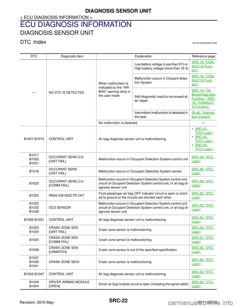
DIAGNOSIS SENSOR UNIT
DTC IndexINFOID:0000000006219956
DTC Diagnostic item Explanation Reference page— NO DTC IS DETECTED. When malfunction is
indicated by the “AIR
BAG” warning lamp in
the user modeLow battery voltage (Less than 9 V) or
High battery voltage (more than 16 V)
SRC-19, "
CON-
SULT-III Func-
tion".
Malfunction occurs in Occpant detac-
tion System SRC-19, "
CON-
SULT-III Func-
tion".
Self-diagnostic result is not erased af-
ter repair SRC-14, "
On
Board Diagnosis
Function",
SRC-
19, "CONSULT-
III Function".
Intermittent malfunction is detected in
the past GI-40, "
Intermit-
tent Incident"
No malfunction is detected —
B1001-B1015 CONTROL UNIT Air bag diagnosis sensor unit is malfunctioning
SRC-41,
"DTC Logic".
SRC-42,
"DTC Logic".
SRC-43,
"DTC Logic".
B1017
B1020
B1021 OCCUPANT SENS C/U
[UNIT FAIL]
Malfunction occurs in Occupant Detection System control unit SRC-44, "
DTC
Logic"
B1018OCCUPANT SENS
[UNIT FAIL]
Malfunction occurs in Occupant Detection System sensor SRC-46, "DTC
Logic"
B1022OCCUPANT SENS C/U
[COMM FAIL] Malfunction occurs in Occupant Detection System control unit,
circuit of Occupant Detection System control unit, or air bag di-
agnosis sensor unit SRC-48, "DTC
Logic"
B1023 PASS A/B INDCTR CKT
Front passenger air bag OFF indicator circuit is open or short-
ed to ground or the circuits are shorted each other SRC-50, "DTC
Logic"
B1025
B1032
B1048
OCS SENSOR Malfunction occurs in Occupant Detection System control unit,
circuit of Occupant Detection System control unit, or air bag di-
agnosis sensor unit SRC-52, "DTC
Logic"
B1026-B1031 CONTROL UNIT Air bag diagnosis sensor unit is malfunctioning
SRC-54, "DTC
Logic".
B1033
B1034 CRASH ZONE SEN
[UNIT FAIL]
Crash zone sensor is malfunctioning
SRC-55, "
DTC
Logic".
B1035 CRASH ZONE SEN
[COMM FAIL] Crash zone sensor is malfunctioning SRC-57, "
DTC
Logic".
B1036 CRASH ZONE SEN
[UNMATCH]
Crash zone sensor is out of the specified specification SRC-59, "
DTC
Logic".
B1037
B1039
B1041 CRASH ZONE SEN1 Crash zone
sensor is malfunctioning SRC-60, "
DTC
Logic".
B1042-B1047 CONTROL UNIT Air bag diagnosis sensor unit is malfunctioning SRC-62, "
DTC
Logic".
B1049
B1054 DRIVER AIRBAG MODULE
[OPEN]
Driver air bag module circuit is open (including the spiral cable)
SRC-63, "
DTC
Logic".
Revision: 2010 May2011 QX56
Page 4816 of 5598
![INFINITI QX56 2011 Factory Service Manual
DIAGNOSIS SENSOR UNITSRC-23
< ECU DIAGNOSIS INFORMATION >
C
DE
F
G
I
J
K L
M A
B
SRC
N
O P
B1050
B1055 DRIVER AIRBAG MODULE
[VB-SHORT] Driver air bag module circuit is shorted to power supply circuit INFINITI QX56 2011 Factory Service Manual
DIAGNOSIS SENSOR UNITSRC-23
< ECU DIAGNOSIS INFORMATION >
C
DE
F
G
I
J
K L
M A
B
SRC
N
O P
B1050
B1055 DRIVER AIRBAG MODULE
[VB-SHORT] Driver air bag module circuit is shorted to power supply circuit](/manual-img/42/57033/w960_57033-4815.png)
DIAGNOSIS SENSOR UNITSRC-23
< ECU DIAGNOSIS INFORMATION >
C
DE
F
G
I
J
K L
M A
B
SRC
N
O P
B1050
B1055 DRIVER AIRBAG MODULE
[VB-SHORT] Driver air bag module circuit is shorted to power supply circuit
(including the spiral cable) SRC-65, "DTC
Logic".
B1051
B1056 DRIVER AIRBAG MODULE
[GND-SHORT] Driver air bag module circuit is shorted to ground (including the
spiral cable) SRC-67, "
DTC
Logic".
B1052
B1057 DRIVER AIRBAG MODULE
[SHORT] Driver air bag module circuits are shorted to each other (includ-
ing spiral cable) SRC-69, "
DTC
Logic".
B1058-B1063 CONTROL UNIT Air bag diagnosis sensor unit is malfunctioning SRC-71, "
DTC
Logic".
B1065
B1070 ASSIST A/B MODULE
[OPEN]
Passenger air bag module circuit is open SRC-72, "
DTC
Logic".
B1066
B1071 ASSIST A/B MODULE
[VB-SHORT] Passenger air bag module circuit is shorted to power supply
circuit SRC-74, "
DTC
Logic".
B1067
B1072 ASSIST A/B MODULE
[GND-SHORT]
Passenger air bag module circuit is shorted to ground SRC-76, "
DTC
Logic".
B1068
B1073 ASSIST A/B MODULE
[SHORT]
Passenger air bag module circuits are shorted to each other SRC-78, "
DTC
Logic".
B1074-B1079 CONTROL UNIT Air bag diagnosis sensor unit is malfunctioning SRC-80, "
DTC
Logic".
B1080
B1096 DRIVER AIRBAG MODULE
[SHORT] Driver air bag module circuits are shorted to each other (includ-
ing spiral cable) SRC-81, "
DTC
Logic".
B1081 PRE-TEN FRONT RH
[OPEN]
Seat belt pre-tensioner RH circuit is open SRC-83, "
DTC
Logic".
B1082 PRE-TEN FRONT RH
[VB-SHORT] Seat belt pre-tensioner RH circuit is shorted to power supply
circuit SRC-85, "
DTC
Logic".
B1083 PRE-TEN FRONT RH
[GND-SHORT] Seat belt pre-tensioner RH circuit is shorted to ground SRC-87, "
DTC
Logic".
B1084 PRE-TEN FRONT RH
[SHORT]
Seat belt pre-tensioner RH circuits are shorted to each other SRC-89, "
DTC
Logic".
B1086 PRE-TEN FRONT LH
[OPEN] Seat belt pre-tensioner LH circuit is open
SRC-91, "
DTC
Logic".
B1087 PRE-TEN FRONT LH
[VB-SHORT] Seat belt pre-tensioner LH circuit is shorted to power supply
circuit SRC-93, "
DTC
Logic".
B1088 PRE-TEN FRONT LH
[GND-SHORT]
Seat belt pre-tensioner LH circuit is shorted to ground SRC-95, "
DTC
Logic".
B1089 PRE-TEN FRONT LH
[SHORT]
Seat belt pre-tensioner LH circuits are shorted to each other SRC-97, "
DTC
Logic".
B1090-B1095 CONTROL UNIT Air bag diagnosis sensor unit is malfunctioning SRC-99, "
DTC
Logic".
B 11 0 6 - B 1111 C O N T R O L U N I T A i r b a g d i a g n o s i s s e n s o r u n i t i s m a l f u n c t i o n i n g SRC-100, "
DTC
Logic".
B 111 3
B 111 4 SATELLITE SENS RH
[UNIT FAIL]
Front satellite sensor RH is malfunctioning SRC-101, "
DTC
Logic".
B 111 5 SATELLITE SENS RH
[COMM FAIL] Front satellite sensor RH is malfunctioning
SRC-103, "
DTC
Logic".
B 111 6 SATELLITE SENS RH
[UNMATCH] Front satellite sensor RH is out of the specified specification SRC-105, "
DTC
Logic".
B 111 8
B 111 9 SATELLITE SENS LH
[UNIT FAIL]
Front satellite sensor LH is malfunctioning SRC-106, "
DTC
Logic".
B1120 SATELLITE SENS LH
[COMM FAIL] Front satellite sensor LH is malfunctioning
SRC-108, "
DTC
Logic".
B1121 SATELLITE SENS LH
[UNMATCH] Front satellite sensor LH is out of the specified specification SRC-110, "
DTC
Logic".
DTC Diagnostic item Explanation Reference page
Revision: 2010 May2011 QX56
Page 4856 of 5598
B1049, B1054 DRIVER AIR BAG MODULE
SRC-63
< DTC/CIRCUIT DIAGNOSIS >
C
D E
F
G
I
J
K L
M A
B
SRC
N
O P
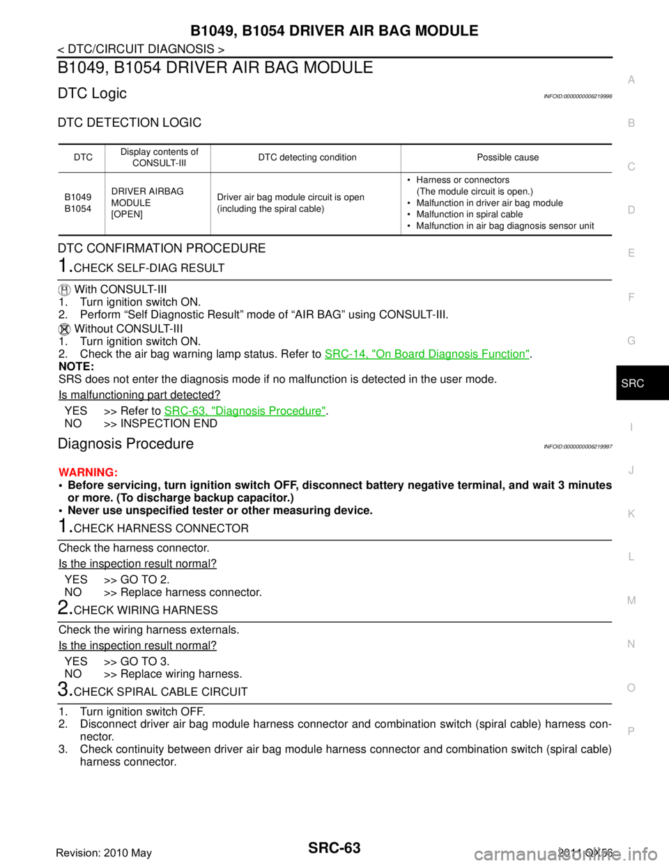
B1049, B1054 DRIVER AIR BAG MODULE
DTC LogicINFOID:0000000006219996
DTC DETECTION LOGIC
DTC CONFIRMATION PROCEDURE
1.CHECK SELF-DIAG RESULT
With CONSULT-III
1. Turn ignition switch ON.
2. Perform “Self Diagnostic Result” mode of “AIR BAG” using CONSULT-III.
Without CONSULT-III
1. Turn ignition switch ON.
2. Check the air bag warning lamp status. Refer to SRC-14, "
On Board Diagnosis Function".
NOTE:
SRS does not enter the diagnosis mode if no malfunction is detected in the user mode.
Is malfunctioning part detected?
YES >> Refer to SRC-63, "Diagnosis Procedure".
NO >> INSPECTION END
Diagnosis ProcedureINFOID:0000000006219997
WARNING:
Before servicing, turn ignition sw itch OFF, disconnect battery negative terminal, and wait 3 minutes
or more. (To discharge backup capacitor.)
Never use unspecified tester or other measuring device.
1.CHECK HARNESS CONNECTOR
Check the harness connector.
Is the inspection result normal?
YES >> GO TO 2.
NO >> Replace harness connector.
2.CHECK WIRING HARNESS
Check the wiring harness externals.
Is the inspection result normal?
YES >> GO TO 3.
NO >> Replace wiring harness.
3.CHECK SPIRAL CABLE CIRCUIT
1. Turn ignition switch OFF.
2. Disconnect driver air bag module harness connector and combination switch (spiral cable) harness con- nector.
3. Check continuity between driver air bag module har ness connector and combination switch (spiral cable)
harness connector.
DTC Display contents of
CONSULT-III DTC detecting condition Possible cause
B1049
B1054 DRIVER AIRBAG
MODULE
[OPEN] Driver air bag module circuit is open
(including the spiral cable) Harness or connectors
(The module circuit is open.)
Malfunction in driver air bag module
Malfunction in spiral cable
Malfunction in air bag diagnosis sensor unit
Revision: 2010 May2011 QX56
Page 4858 of 5598
B1050, B1055 DRIVER AIR BAG MODULE
SRC-65
< DTC/CIRCUIT DIAGNOSIS >
C
D E
F
G
I
J
K L
M A
B
SRC
N
O P
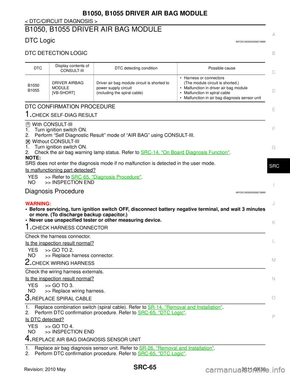
B1050, B1055 DRIVER AIR BAG MODULE
DTC LogicINFOID:0000000006219998
DTC DETECTION LOGIC
DTC CONFIRMATION PROCEDURE
1.CHECK SELF-DIAG RESULT
With CONSULT-III
1. Turn ignition switch ON.
2. Perform “Self Diagnostic Result” mode of “AIR BAG” using CONSULT-III.
Without CONSULT-III
1. Turn ignition switch ON.
2. Check the air bag warning lamp status. Refer to SRC-14, "
On Board Diagnosis Function".
NOTE:
SRS does not enter the diagnosis mode if no malfunction is detected in the user mode.
Is malfunctioning part detected?
YES >> Refer to SRC-65, "Diagnosis Procedure".
NO >> INSPECTION END
Diagnosis ProcedureINFOID:0000000006219999
WARNING:
Before servicing, turn ignition sw itch OFF, disconnect battery negative terminal, and wait 3 minutes
or more. (To discharge backup capacitor.)
Never use unspecified tester or other measuring device.
1.CHECK HARNESS CONNECTOR
Check the harness connector.
Is the inspection result normal?
YES >> GO TO 2.
NO >> Replace harness connector.
2.CHECK WIRING HARNESS
Check the wiring harness externals.
Is the inspection result normal?
YES >> GO TO 3.
NO >> Replace wiring harness.
3.REPLACE SPIRAL CABLE
1. Replace combination switch (spiral cable). Refer to SR-14, "
Removal and Installation".
2. Perform DTC confirmation procedure. Refer to SRC-65, "
DTC Logic".
Is DTC detected?
YES >> GO TO 4.
NO >> INSPECTION END
4.REPLACE AIR BAG DIAGNOSIS SENSOR UNIT
1. Replace air bag diagnosis sensor unit. Refer to SR-26, "
Removal and Installation".
2. Perform DTC confirmation procedure. Refer to SRC-65, "
DTC Logic".
DTCDisplay contents of
CONSULT-III DTC detecting condition Possible cause
B1050
B1055 DRIVER AIRBAG
MODULE
[VB-SHORT] Driver air bag module circuit is shorted to
power supply circuit
(including the spiral cable) Harness or connectors
(The module circuit is shorted.)
Malfunction in driver air bag module
Malfunction in spiral cable
Malfunction in air bag diagnosis sensor unit
Revision: 2010 May2011 QX56
Page 4860 of 5598
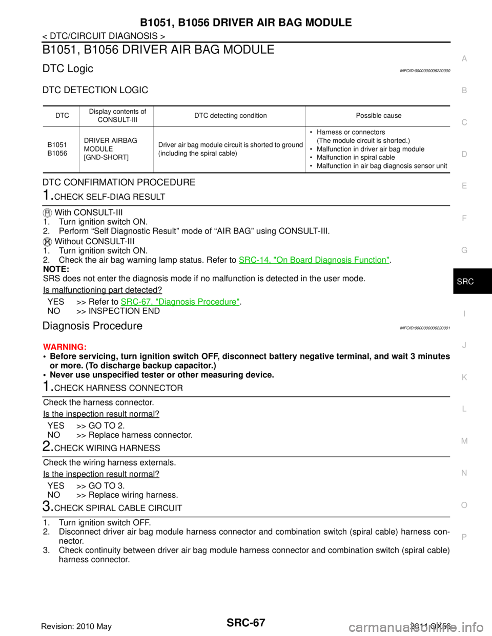
B1051, B1056 DRIVER AIR BAG MODULE
SRC-67
< DTC/CIRCUIT DIAGNOSIS >
C
D E
F
G
I
J
K L
M A
B
SRC
N
O P
B1051, B1056 DRIVER AIR BAG MODULE
DTC LogicINFOID:0000000006220000
DTC DETECTION LOGIC
DTC CONFIRMATION PROCEDURE
1.CHECK SELF-DIAG RESULT
With CONSULT-III
1. Turn ignition switch ON.
2. Perform “Self Diagnostic Result” mode of “AIR BAG” using CONSULT-III.
Without CONSULT-III
1. Turn ignition switch ON.
2. Check the air bag warning lamp status. Refer to SRC-14, "
On Board Diagnosis Function".
NOTE:
SRS does not enter the diagnosis mode if no malfunction is detected in the user mode.
Is malfunctioning part detected?
YES >> Refer to SRC-67, "Diagnosis Procedure".
NO >> INSPECTION END
Diagnosis ProcedureINFOID:0000000006220001
WARNING:
Before servicing, turn ignition sw itch OFF, disconnect battery negative terminal, and wait 3 minutes
or more. (To discharge backup capacitor.)
Never use unspecified tester or other measuring device.
1.CHECK HARNESS CONNECTOR
Check the harness connector.
Is the inspection result normal?
YES >> GO TO 2.
NO >> Replace harness connector.
2.CHECK WIRING HARNESS
Check the wiring harness externals.
Is the inspection result normal?
YES >> GO TO 3.
NO >> Replace wiring harness.
3.CHECK SPIRAL CABLE CIRCUIT
1. Turn ignition switch OFF.
2. Disconnect driver air bag module harness connector and combination switch (spiral cable) harness con- nector.
3. Check continuity between driver air bag module har ness connector and combination switch (spiral cable)
harness connector.
DTC Display contents of
CONSULT-III DTC detecting condition Possible cause
B1051
B1056 DRIVER AIRBAG
MODULE
[GND-SHORT] Driver air bag module circuit is shorted to ground
(including the spiral cable) Harness or connectors
(The module circuit is shorted.)
Malfunction in driver air bag module
Malfunction in spiral cable
Malfunction in air bag diagnosis sensor unit
Revision: 2010 May2011 QX56