2011 INFINITI QX56 TPMS
[x] Cancel search: TPMSPage 185 of 5598

AV
DIAGNOSIS SYSTEM (AV CONTROL UNIT)AV-37
< SYSTEM DESCRIPTION >
C
DE
F
G H
I
J
K L
M B A
O P
Vehicle CAN Diagnosis
CAN communication status and error counter is displayed.
The error counter displays “OK” if any malfunction was not
detected in the past and displays “0 ” if a malfunction is detected. It
increases by 1 if the condition is normal at the next ignition switch
ON cycle. The upper limit of the counter is 39.
The error counter is erased if “Reset” is pressed.
NOTE:
“???” indicates UNKWN.
AV COMM Diagnosis
AV COMM CIRCUIT
Switches Connection Error When either one of the following items are
detected:
multifunction switch power supply and
ground circuits were malfunctioning.
AV communication circuits between AV
control unit and multifunction switch are
malfunctioning. Multifunction switch power supply and
ground circuits.
AV communication circuits between AV control unit and multifunction switch.
AV COMM CIRCUIT
AVM Connection Error When either one of the following items are
detected:
around view monitor control unit power
supply and ground circuits are malfunc-
tioning.
AV communication circuits between AV control unit and around view monitor
control unit are malfunctioning. Around view monitor control unit power
supply and ground circuits.
AV communication circuits between AV control unit and around view monitor
control unit.
AV COMM CIRCUIT
Sonar Connection Error When either one of the following items are
detected:
sonar control unit power supply and
ground circuits are malfunctioning.
AV communication circuits between AV control unit and sonar control unit are
malfunctioning. Sonar control unit power supply and
ground circuits.
AV communication circuits between AV control unit and sonar control unit.
AV COMM CIRCUIT
Switches Connection Error
Sonar Connection Error
AVM Connection Error AV communication circuits between AV
control unit and multifunction switch are
malfunctioning.AV communication circuits between AV
control unit and multifunction switch.
AV COMM CIRCUIT
Switches Connection Error
Sonar Connection Error
AVM Connection Error
2nd Display Connection Error Error item Description Possible malfunction factor/Action to take
Items Display (Current)
Malfunction counter
(Past)
Tx(HVAC) OK / ??? OK / 0 – 39
Rx(ECM) OK / ??? OK / 0 – 39
Rx(Cluster) OK / ??? OK / 0 – 39
Rx(HVAC) OK / ??? OK / 0 – 39
Rx(USM) OK / ??? OK / 0 – 39
Rx(TPMS) OK / ??? OK / 0 – 39
Rx(STRG) OK / ??? OK / 0 – 39
Rx(ACC) OK / ??? OK / 0 – 39
RX(VDC) OK / ??? OK / 0 – 39
JSNIA2391ZZ
Revision: 2010 May2011 QX56
Page 390 of 5598

BCS-2
BATTERY SAVER ....................................................29
BATTERY SAVER : CONSULT-III Function (BCM
- BATTERY SAVER) ........................................... ...
29
TRUNK ................................................................... ...30
TRUNK : CONSULT-III Function (BCM - TRUNK) ...30
THEFT ALM ........................................................... ...30
THEFT ALM : CONSULT-III Function (BCM -
THEFT) ...................................................................
30
RETAIND PWR ...................................................... ...31
RETAIND PWR : CONSULT-III Function (BCM -
RETAINED PWR) ...................................................
31
SIGNAL BUFFER ................................................... ...31
SIGNAL BUFFER : CONSULT-III Function (BCM
- SIGNAL BUFFER) ................................................
31
ECU DIAGNOSIS INFORMATION ..............33
BCM ................................................................ ...33
Reference Value .................................................. ...33
Fail-safe ..................................................................54
DTC Inspection Priority Chart ..............................56
DTC Index ..............................................................57
WIRING DIAGRAM .....................................60
BCM ................................................................ ...60
Wiring Diagram .................................................... ...60
BASIC INSPECTION ...................................67
INSPECTION AND ADJUSTMENT ................ ...67
ADDITIONAL SERVICE WHEN REPLACING
CONTROL UNIT (BCM) ......................................... ...
67
ADDITIONAL SERVICE WHEN REPLACING
CONTROL UNIT (BCM) : Description ....................
67
ADDITIONAL SERVICE WHEN REPLACING
CONTROL UNIT (BCM) : Work Procedure ............
67
CONFIGURATION (BCM) ...................................... ...67
CONFIGURATION (BCM) : Description .................67
CONFIGURATION (BCM) : Work Procedure .........68
CONFIGURATION (BCM) : Configuration list ........69
DTC/CIRCUIT DIAGNOSIS ........................70
U1000 CAN COMM ........................................ ...70
Description ........................................................... ...70
DTC Logic ...............................................................70
Diagnosis Procedure ...............................................70
U1010 CONTROL UNIT (CAN) .........................71
DTC Logic ............................................................ ...71
Diagnosis Procedure ...............................................71
U0415 VEHICLE SPEED ...................................72
Description ........................................................... ...72
DTC Logic ...............................................................72
Diagnosis Procedure ...............................................72
B2562 LOW VOLTAGE .....................................73
DTC Logic ............................................................ ...73
Diagnosis Procedure ...............................................73
B26E7 TPMS CAN COMM ............................. ...74
DTC Logic ............................................................ ...74
Diagnosis Procedure ...............................................74
POWER SUPPLY AND GROUND CIRCUIT .....75
Diagnosis Procedure ............................................ ...75
COMBINATION SWITCH OUTPUT CIRCUIT ...76
Diagnosis Procedure ...............................................76
COMBINATION SWITCH INPUT CIRCUIT .......78
Diagnosis Procedure ............................................ ...78
SYMPTOM DIAGNOSIS ............................80
COMBINATION SWITCH SYSTEM SYMP-
TOMS .............................................................. ...
80
Symptom Table .................................................... ...80
REMOVAL AND INSTALLATION ..............81
BCM ................................................................ ...81
Removal and Installation ...................................... ...81
COMBINATION SWITCH ..................................82
Exploded View ..................................................... ...82
Removal and Installation .........................................82
Revision: 2010 May2011 QX56
Page 445 of 5598

BCS
BCM
BCS-57
< ECU DIAGNOSIS INFORMATION >
C
D E
F
G H
I
J
K L
B A
O P
N
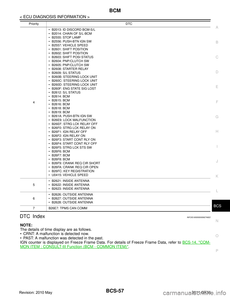
DTC IndexINFOID:0000000006274822
NOTE:
The details of time display are as follows.
CRNT: A malfunction is detected now.
PAST: A malfunction was detected in the past.
IGN counter is displayed on Freeze Frame Data. For details of Freeze Frame Data, refer to
BCS-14, "
COM-
MON ITEM : CONSULT-III Function (BCM - COMMON ITEM)".
4 B2013: ID DISCORD BCM-S/L
B2014: CHAIN OF S/L-BCM
B2555: STOP LAMP
B2556: PUSH-BTN IGN SW
B2557: VEHICLE SPEED
B2601: SHIFT POSITION
B2602: SHIFT POSITION
B2603: SHIFT POSI STATUS
B2604: PNP/CLUTCH SW
B2605: PNP/CLUTCH SW
B2608: STARTER RELAY
B2609: S/L STATUS
B260B: STEERING LOCK UNIT
B260C: STEERING LOCK UNIT
B260D: STEERING LOCK UNIT
B260F: ENG STATE SIG LOST
B2612: S/L STATUS
B2614: BCM
B2615: BCM
B2616: BCM
B2618: BCM
B2619: BCM
B261A: PUSH-BTN IGN SW
B26E9: LOCK MALFUNCTION
B26EF: STRG LCK RELAY OFF
B26F0: STRG LCK RELAY ON
B26F1: IGN RELAY OFF
B26F2: IGN RELAY ON
B26F3: START CONT RLY ON
B26F4: START CONT RLY OFF
B26F5: STRG LCK STS SW
B26F6: BCM
B26F7: BCM
B26F8: BCM
B26F9: CRANK REQ CIR SHORT
B26FA: CRANK REQ CIR OPEN
B26FC: KEY REGISTRATION
U0415: VEHICLE SPEED
5 B2621: INSIDE ANTENNA
B2622: INSIDE ANTENNA
B2623: INSIDE ANTENNA
6 B2626: OUTSIDE ANTENNA
B2627: OUTSIDE ANTENNA
B2628: OUTSIDE ANTENNA
7 B26E7: TPMS CAN COMM
Priority DTC
Revision: 2010 May2011 QX56
Page 446 of 5598

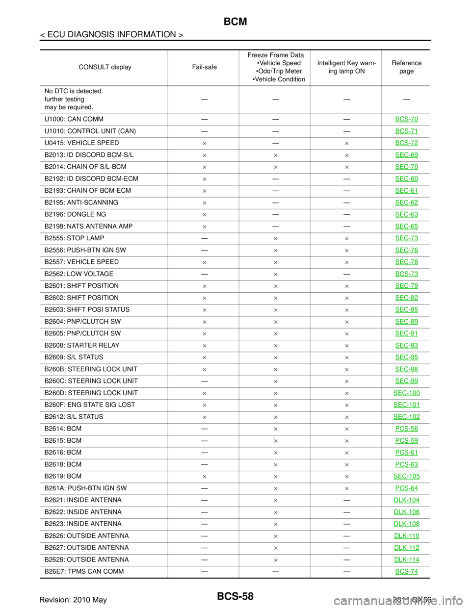
BCS-58
< ECU DIAGNOSIS INFORMATION >
BCM
CONSULT display Fail-safeFreeze Frame Data
Vehicle Speed
Odo/Trip Meter
Vehicle Condition Intelligent Key warn-
ing lamp ON Reference
page
No DTC is detected.
further testing
may be required. ————
U1000: CAN COMM — — — BCS-70
U1010: CONTROL UNIT (CAN) — — —BCS-71
U0415: VEHICLE SPEED×— ×BCS-72
B2013: ID DISCORD BCM-S/L ××× SEC-69
B2014: CHAIN OF S/L-BCM××× SEC-70
B2192: ID DISCORD BCM-ECM×—— SEC-60
B2193: CHAIN OF BCM-ECM ×—— SEC-61
B2195: ANTI-SCANNING ×—— SEC-62
B2196: DONGLE NG ×—— SEC-63
B2198: NATS ANTENNA AMP ×—— SEC-65
B2555: STOP LAMP — ××SEC-73
B2556: PUSH-BTN IGN SW — ××SEC-76
B2557: VEHICLE SPEED ××× SEC-78
B2562: LOW VOLTAGE — ×—BCS-73
B2601: SHIFT POSITION ××× SEC-79
B2602: SHIFT POSITION××× SEC-82
B2603: SHIFT POSI STATUS××× SEC-85
B2604: PNP/CLUTCH SW××× SEC-89
B2605: PNP/CLUTCH SW××× SEC-91
B2608: STARTER RELAY××× SEC-93
B2609: S/L STATUS××× SEC-95
B260B: STEERING LOCK UNIT××× SEC-98
B260C: STEERING LOCK UNIT — ××SEC-99
B260D: STEERING LOCK UNIT ××× SEC-100
B260F: ENG STATE SIG LOST××× SEC-101
B2612: S/L STATUS××× SEC-102
B2614: BCM — ××PCS-56
B2615: BCM — ××PCS-59
B2616: BCM — ××PCS-61
B2618: BCM — ××PCS-63
B2619: BCM ××× SEC-105
B261A: PUSH-BTN IGN SW — ××PCS-64
B2621: INSIDE ANTENNA — ×—DLK-104
B2622: INSIDE ANTENNA — ×—DLK-106
B2623: INSIDE ANTENNA — ×—DLK-108
B2626: OUTSIDE ANTENNA — ×—DLK-110
B2627: OUTSIDE ANTENNA — ×—DLK-112
B2628: OUTSIDE ANTENNA — ×—DLK-114
B26E7: TPMS CAN COMM — — — BCS-74
Revision: 2010 May2011 QX56
Page 457 of 5598

BCS
INSPECTION AND ADJUSTMENTBCS-69
< BASIC INSPECTION >
C
DE
F
G H
I
J
K L
B A
O P
N
CONFIGURATION (BCM)
: Configuration listINFOID:0000000006274828
Items and setting value that are written in BCM by t he write configuration can be checked by “READ CONFIG-
URATION” as shown in the following table.
SETTING ITEM NOTE
Items Setting value
HZRD (SHCK DTCT ULK) FUNC WITH — UNLOCK WITH SHOCK WITHOUT —
CAN CONNECTION UNIT MODE1 —
NISSAN/INFINITI SETTING INFINITI — AUTO LIGHT WITH —
RAIN SENSOR CONFIG WITH — THEFT ALM AREA MODE2 —
AT DOOR LK VHCL SPED SET MODE2 — TPMS TPMS SBF —
Revision: 2010 May2011 QX56
Page 462 of 5598

BCS-74
< DTC/CIRCUIT DIAGNOSIS >
B26E7 TPMS CAN COMM
B26E7 TPMS CAN COMM
DTC LogicINFOID:0000000006274839
DTC DETECTION LOGIC
DTC CONFIRMATION PROCEDURE
1.DTC CONFIRMATION
1. Erase the DTC.
2. Turn ignition switch OFF.
3. Perform the “Self Diagnostic Result” of BCM with CONS ULT-III, when passed 2 seconds or more after the
ignition switch is turned ON.
Is any DTC detected?
YES >> Refer to BCS-74, "Diagnosis Procedure".
NO >> INSPECTION END
Diagnosis ProcedureINFOID:0000000006274840
NOTE:
If DTC “B26E7” detected along with DTC “U1000” , first diagnose the DTC “U1000”. Refer to BCS-70, "
Diagno-
sis Procedure".
1.LOW TIRE PRESSURE WARNING CONTRO L UNIT SELF DIAGNOSTIC RESULT
Perform “Self Diagnostic Result” of low tire pressu re warning control unit with CONSULT-III. Refer to WT-12,
"CONSULT-III Function".
Is any DTC detected?
YES >> GO TO 2.
NO >> GO TO 4.
2.LOW TIRE PRESSURE WARNING CONTROL UNIT DIAGNOSIS
Perform low tire pressure warning control uni t component diagnosis of detected DTC. Refer to WT-18, "
DTC
Index".
>> GO TO 3.
3.BCM SELF DIAGNOSTIC RESULT
Erase DTC of BCM, and perform “Self Diagnostic Result” again.
Is DTC
“B26E7” detected?
YES >> Replace BCM. Refer to BCS-81, "Removal and Installation".
NO >> INSPECTION END
4.REPLACE LOW TIRE PRESSURE WA RNING CONTROL UNIT TEMPORARILY
Remove low tire pressure warning control unit, and in stall normal low tire pressure warning control unit.
>> GO TO 5.
5.BCM SELF-DIAGNOSTIC RESULT
Erase DTC of BCM, and perform “S elf Diagnostic Result” of BCM again.
Is DTC
“B26E7” detected?
YES >> Replace BCM. Refer to BCS-81, "Removal and Installation".
NO >> Replace low tire pressure warning control unit. Refer to WT-65, "
Removal and Installation".
DTC CONSULT-III display description DTC Detection Condition Probable cause
B26E7 TPMS CAN COMM When ignition switch is ON, BCM cannot re-
ceived CAN communication signal from low
tire pressure warn
ing control unit. CAN communication system
Low tire pressure warning control unit
BCM
Revision: 2010 May2011 QX56
Page 1788 of 5598

DLK-252
< REMOVAL AND INSTALLATION >
CAB MOUNTING INSULATOR
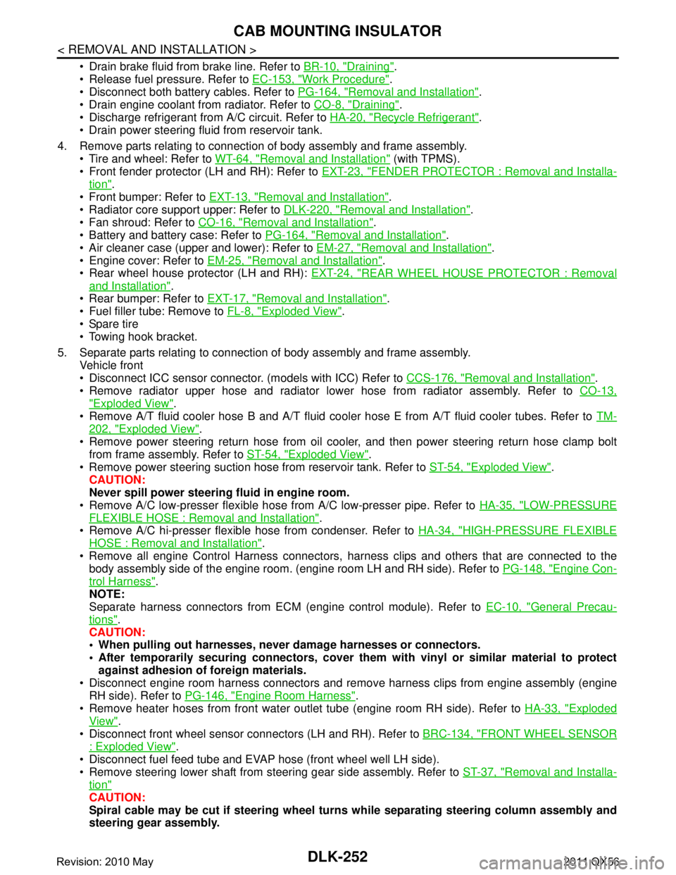
Drain brake fluid from brake line. Refer to BR-10, "Draining".
Release fuel pressure. Refer to EC-153, "
Work Procedure".
Disconnect both battery cables. Refer to PG-164, "
Removal and Installation".
Drain engine coolant from radiator. Refer to CO-8, "
Draining".
Discharge refrigerant from A/C circuit. Refer to HA-20, "
Recycle Refrigerant".
Drain power steering fluid from reservoir tank.
4. Remove parts relating to connection of body assembly and frame assembly. Tire and wheel: Refer to WT-64, "
Removal and Installation" (with TPMS).
Front fender protector (LH and RH): Refer to EXT-23, "
FENDER PROTECTOR : Removal and Installa-
tion".
Front bumper: Refer to EXT-13, "
Removal and Installation".
Radiator core support upper: Refer to DLK-220, "
Removal and Installation".
Fan shroud: Refer to CO-16, "
Removal and Installation".
Battery and battery case: Refer to PG-164, "
Removal and Installation".
Air cleaner case (upper and lower): Refer to EM-27, "
Removal and Installation".
Engine cover: Refer to EM-25, "
Removal and Installation".
Rear wheel house protector (LH and RH): EXT-24, "
REAR WHEEL HOUSE PROTECTOR : Removal
and Installation".
Rear bumper: Refer to EXT-17, "
Removal and Installation".
Fuel filler tube: Remove to FL-8, "
Exploded View".
Spare tire
Towing hook bracket.
5. Separate parts relating to connection of body assembly and frame assembly. Vehicle front
Disconnect ICC sensor connector. (models with ICC) Refer to CCS-176, "
Removal and Installation".
Remove radiator upper hose and radiator lower hose from radiator assembly. Refer to CO-13,
"Exploded View".
Remove A/T fluid cooler hose B and A/T fluid cooler hose E from A/T fluid cooler tubes. Refer to TM-
202, "Exploded View".
Remove power steering return hose from oil cooler, and then power steering return hose clamp bolt from frame assembly. Refer to ST-54, "
Exploded View".
Remove power steering suction hose from reservoir tank. Refer to ST-54, "
Exploded View".
CAUTION:
Never spill power steering fluid in engine room.
Remove A/C low-presser flexible hose from A/C low-presser pipe. Refer to HA-35, "
LOW-PRESSURE
FLEXIBLE HOSE : Removal and Installation".
Remove A/C hi-presser flexible hose from condenser. Refer to HA-34, "
HIGH-PRESSURE FLEXIBLE
HOSE : Removal and Installation".
Remove all engine Control Harness connectors, har ness clips and others that are connected to the
body assembly side of the engine room. (engine room LH and RH side). Refer to PG-148, "
Engine Con-
trol Harness".
NOTE:
Separate harness connectors from ECM (engine control module). Refer to EC-10, "
General Precau-
tions".
CAUTION:
When pulling out harnesses, never damage harnesses or connectors.
After temporarily securing connectors, cover th em with vinyl or similar material to protect
against adhesion of foreign materials.
Disconnect engine room harness connectors and remo ve harness clips from engine assembly (engine
RH side). Refer to PG-146, "
Engine Room Harness".
Remove heater hoses from front water outlet tube (engine room RH side). Refer to HA-33, "
Exploded
View".
Disconnect front wheel sensor connectors (LH and RH). Refer to BRC-134, "
FRONT WHEEL SENSOR
: Exploded View".
Disconnect fuel feed tube and EVAP hos e (front wheel well LH side).
Remove steering lower shaft from steering gear side assembly. Refer to ST-37, "
Removal and Installa-
tion"
CAUTION:
Spiral cable may be cut if steering wheel turns while separating steering column assembly and
steering gear assembly.
Revision: 2010 May2011 QX56
Page 2981 of 5598

ABBREVIATIONSGI-17
< HOW TO USE THIS MANUAL >
C
DE
F
G H
I
J
K L
M B
GI
N
O P
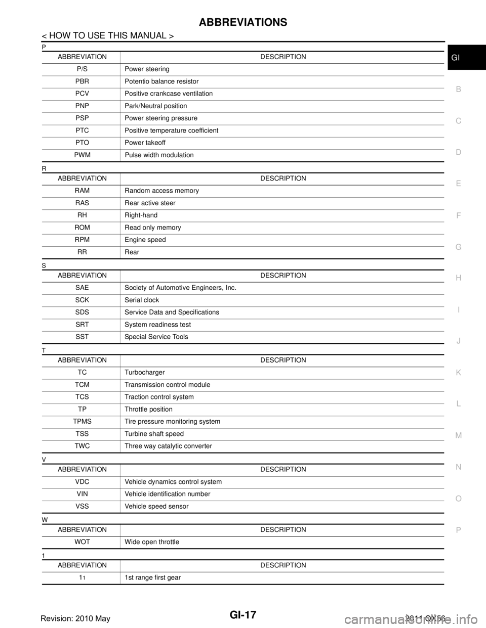
P
R
S
T
V
W
1
ABBREVIATION DESCRIPTION P/S Power steering
PBR Potentio balance resistor
PCV Positive crankcase ventilation
PNP Park/Neutral position PSP Power steering pressurePTC Positive temperature coefficient
PTO Power takeoff
PWM Pulse width modulation
ABBREVIATION DESCRIPTION RAM Random access memoryRAS Rear active steer RH Right-hand
ROM Read only memory RPM Engine speed RR Rear
ABBREVIATION DESCRIPTION SAE Society of Automoti ve Engineers, Inc.
SCK Serial clock
SDS Service Data and Specifications SRT System readiness testSST Special Service Tools
ABBREVIATION DESCRIPTION TC Turbocharger
TCM Transmission control module TCS Traction control system TP Throttle position
TPMS Tire pressure monitoring system TSS Turbine shaft speed
TWC Three way catalytic converter
ABBREVIATION DESCRIPTION VDC Vehicle dynamics control systemVIN Vehicle identification number
VSS Vehicle speed sensor
ABBREVIATION DESCRIPTION WOT Wide open throttle
ABBREVIATION DESCRIPTION 1
11st range first gear
Revision: 2010 May2011 QX56