2011 INFINITI QX56 alternator belt
[x] Cancel search: alternator beltPage 914 of 5598

CHG
CHG-1
ELECTRICAL & POWER CONTROL
C
DE
F
G H
I
J
K L
B
SECTION CHG
A
O P
N
CONTENTS
CHARGING SYSTEM
PRECAUTION ................
...............................3
PRECAUTIONS .............................................. .....3
Precaution for Supplemental Restraint System
(SRS) "AIR BAG" and "SEAT BELT PRE-TEN-
SIONER" ............................................................. ......
3
Precaution Necessary for Steering Wheel Rota-
tion after Battery Disconnect .....................................
3
Precaution for Power Generation Voltage Variable
Control System ..........................................................
4
PREPARATION ............................................5
PREPARATION .............................................. .....5
Special Service Tools .......................................... ......5
Commercial Service Tools ........................................5
SYSTEM DESCRIPTION ..............................6
COMPONENT PARTS ................................... .....6
Component Parts Location .................................. ......6
Component Description ............................................6
SYSTEM ..............................................................7
CHARGING SYSTEM ..................................................7
CHARGING SYSTEM : System Diagram ........... ......7
CHARGING SYSTEM : System Description .............7
POWER GENERATION VOLTAGE VARIABLE
CONTROL SYSTEM .............................................. ......
7
POWER GENERATION VOLTAGE VARIABLE
CONTROL SYSTEM : System Diagram ...................
7
POWER GENERATION VOLTAGE VARIABLE
CONTROL SYSTEM : System Description ...............
7
WIRING DIAGRAM ........ ...............................9
CHARGING SYSTEM ..................................... .....9
Wiring Diagram ................................................... ......9
BASIC INSPECTION ...................................13
DIAGNOSIS AND REPAIR WORKFLOW ........13
Work Flow ............................................................ ....13
CHARGING SYSTEM PRELIMINARY IN-
SPECTION ....................................... .................
16
Inspection Procedure ........................................... ....16
POWER GENERATION VOLTAGE VARI-
ABLE CONTROL SYSTEM OPERATION IN-
SPECTION ....................................... .................
17
Inspection Procedure ........................................... ....17
DTC/CIRCUIT DIAGNOSIS .........................19
B TERMINAL CIRCUIT .....................................19
Description ........................................................... ....19
Diagnosis Procedure ...............................................19
L TERMINAL CIRCUIT (OPEN) ........................20
Description ...............................................................20
Diagnosis Procedure ...............................................20
L TERMINAL CIRCUIT (SHORT) .....................22
Description ...............................................................22
Diagnosis Procedure ...............................................22
S TERMINAL CIRCUIT .....................................23
Description ...............................................................23
Diagnosis Procedure ...............................................23
SYMPTOM DIAGNOSIS ..............................24
CHARGING SYSTEM .......................................24
Symptom Table ................................................... ....24
REMOVAL AND INSTALLATION ...............25
ALTERNATOR ................................. .................25
Exploded View ..................................................... ....25
Removal and Installation .........................................26
Inspection ................................................................28
Revision: 2010 May2011 QX56
Page 929 of 5598

CHG-16
< BASIC INSPECTION >
CHARGING SYSTEM PRELIMINARY INSPECTION
CHARGING SYSTEM PRELIMINARY INSPECTION
Inspection ProcedureINFOID:0000000006274866
1.CHECK BATTERY TERMINALS CONNECTION
Check if battery terminals are clean and tight.
Is the inspection result normal?
YES >> GO TO 2.
NO >> Repair battery terminals connection.
2.CHECK FUSE
Check for blown fuse and fusible link.
Is the inspection result normal?
YES >> GO TO 3.
NO >> Replace the blown fuse after repairing the applicable circuit.
3.CHECK “E” TERMINAL CONNECTION
Check if “E” terminal (alternator ground harness) is clean and tight.
Is the inspection result normal?
YES >> GO TO 4.
NO >> Repair “E” terminal connection.
4.CHECK DRIVE BELT TENSION
Check drive belt tension. Refer to EM-20, "
Checking".
Is the inspection result normal?
YES >> INSPECTION END
NO >> Repair as needed.
Unit Power source (Power supply terminals) Fuse No.
Alternator Battery (“S” terminal) 32
Combination meter Ignition switch ON (“L” terminal) 3
Revision: 2010 May2011 QX56
Page 939 of 5598

CHG-26
< REMOVAL AND INSTALLATION >
ALTERNATOR
Type: A002TX1491
Removal and InstallationINFOID:0000000006274878
REMOVAL
1. Disconnect the battery cable from the negative terminal. Refer to PG-164, "Removal and Installation".
2. Remove front under cover. Refer to EXT-25, "
Removal and Installation".
3. Remove drive belt. Refer to EM-20, "
Removal and Installation".
4. Disconnect engine oil pressure switch connector (A) and alter- nator connector (B).
5. Remove harness bracket bolt (C).
6. Remove “B” terminal nut (D) and disconnect “B” terminal har- ness.
JMMIA0363GB
1. Rear bearing 2. Rotor assembly 3. Retainer
4. Front bearing 5. Front bracket assembly 6. Pulley
7. Pulley nut 8. Stator assembly 9. IC voltage regulator assembly
10. Diode assembly 11. Rear bracket assembly 12. Terminal set
Refer to GI-4, "
Components" for symbols in the figure.
JMMIA0364ZZ
Revision: 2010 May2011 QX56
Page 940 of 5598

CHG
ALTERNATORCHG-27
< REMOVAL AND INSTALLATION >
C
DE
F
G H
I
J
K L
B A
O P
N
7. Remove ground harness mounting bolt.
8. Remove alternator mounting bolt (lower), and then alternator mounting bolt (upper).
9. Remove A/T fluid cooler tube (1) from fan shroud (2).
10. Move A/T fluid cooler tube (1) and secure work space.
11. Remove alternator assembly
(2) from underneath the vehicle.
INSTALLATION
Note the following items, and then install in the reverse order of removal.
CAUTION:
Be careful to tighten “B” terminal nut carefully.
Install alternator, and check tension of belt. Refer to EM-20, "
Checking".
For this model, the power genera tion voltage variable control system that controls the power gener-
ation voltage of the alternator has been adopted. Therefore, the power generation voltage variable
control system operation inspectio n should be performed after replacing the alternator, and then
make sure that the system operates normally. Refer to CHG-17, "
Inspection Procedure".
When installing alternator br acket, tighten mounting bolts in
numerical order as shown in the figure.
JMMIA0365ZZ
JMMIA0366ZZ
JMMIA0367ZZ
JMMIA0456ZZ
Revision: 2010 May2011 QX56
Page 2582 of 5598

EM-20
< PERIODIC MAINTENANCE >
DRIVE BELTS
PERIODIC MAINTENANCE
DRIVE BELTS
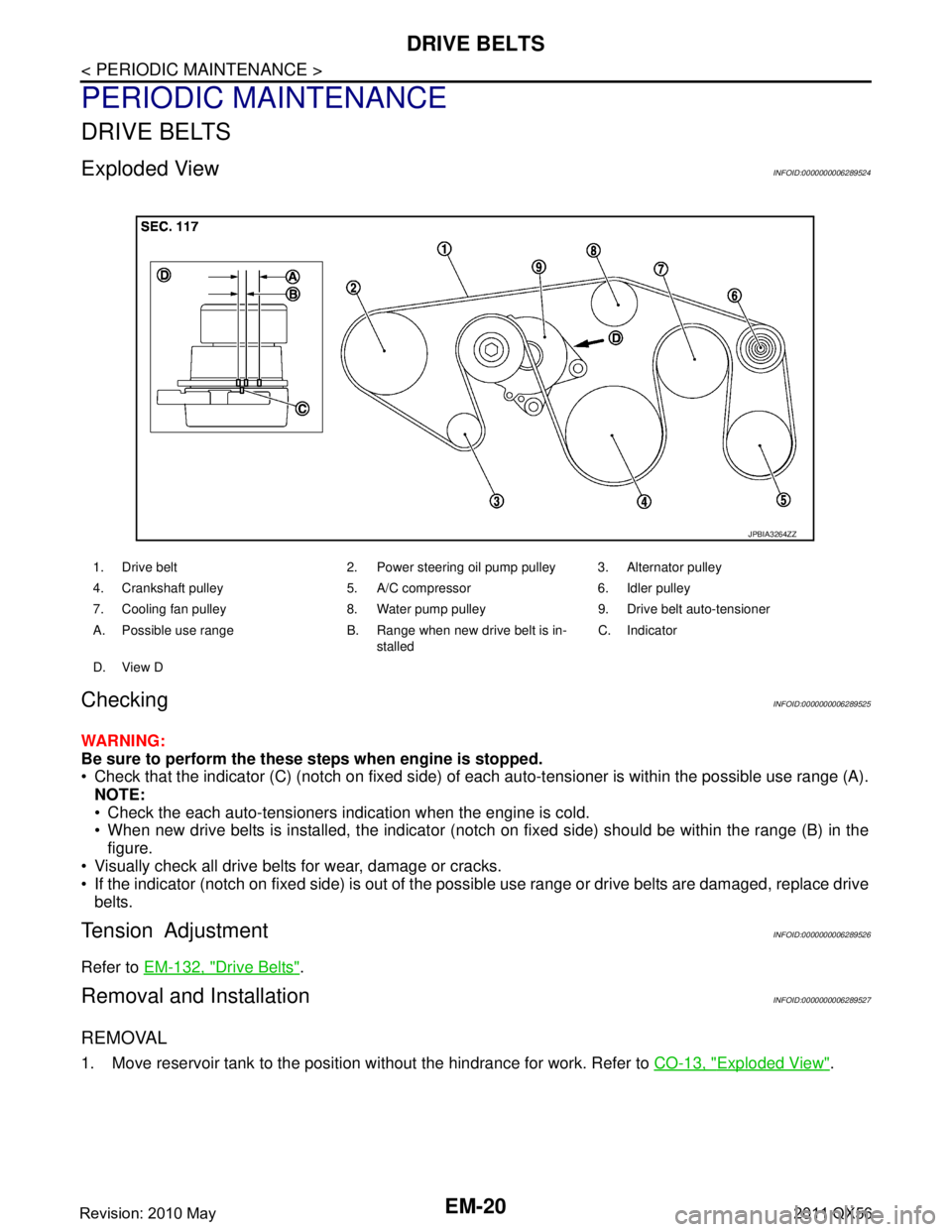
Exploded ViewINFOID:0000000006289524
CheckingINFOID:0000000006289525
WARNING:
Be sure to perform the these steps when engine is stopped.
Check that the indicator (C) (notch on fixed side) of each auto-tensioner is within the possible use range (A).
NOTE:
Check the each auto-tensioners indication when the engine is cold.
When new drive belts is installed, the indicator (notch on fixed side) should be within the range (B) in the\
figure.
Visually check all drive belts for wear, damage or cracks.
If the indicator (notch on fixed side) is out of the possible use range or drive belts are damaged, replace drive
belts.
Tension AdjustmentINFOID:0000000006289526
Refer to EM-132, "Drive Belts".
Removal and InstallationINFOID:0000000006289527
REMOVAL
1. Move reservoir tank to the position without the hindrance for work. Refer to CO-13, "Exploded View".
1. Drive belt 2. Power steering oil pump pulley 3. Alternator pulley
4. Crankshaft pulley 5. A/C compressor 6. Idler pulley
7. Cooling fan pulley 8. Water pump pulley 9. Drive belt auto-tensioner
A. Possible use range B. Range when new drive belt is in-
stalledC. Indicator
D. View D
JPBIA3264ZZ
Revision: 2010 May2011 QX56
Page 2602 of 5598

EM-40
< REMOVAL AND INSTALLATION >
EXHAUST MANIFOLD AND THREE WAY CATALYST
EXHAUST MANIFOLD AND THREE WAY CATALYST
Exploded ViewINFOID:0000000006289550
Removal and InstallationINFOID:0000000006289551
REMOVAL
WARNING:
Perform the work when the exhaust and cooling system have cooled sufficiently.
1. Drain engine coolant from radiator. Refer to CO-8, "
Draining".
CAUTION:
Perform this step when the engine is cold.
Never spill engine coolant on drive belt.
2. Remove reservoir tank. Refer to CO-13, "
Exploded View".
3. Remove drive belt. Refer to EM-20, "
Removal and Installation".
4. Remove power steering oil pump. Refer to ST-48, "
Exploded View".
5. Remove radiator. Refer to CO-13, "
Exploded View".
6. Remove front under cover. Refer to EXT-25, "
Exploded View".
7. Remove front wheels and tires. Refer to WT-64, "
Exploded View".
8. Remove A/C compressor. Refer to HA-30, "
Exploded View".
9. Remove alternator and alternator bracket. Refer to CHG-25, "
Exploded View".
10. Remove exhaust front tube (bank 1 and bank 2). Refer to EX-5, "
Exploded View".
1. Air fuel ratio sensor 1 (bank 2) 2. Exhaust manifold cover (bank 2) 3. Exhaust manifold and three way cat-
alyst (bank 2)
4. Gasket 5. Exhaust manifold and three way cat-
alyst (bank 1)6. Exhaust manifold cover (bank 1)
7. Air fuel ratio sensor 1 (bank 1)
Refer to GI-4, "
Components" for symbols in the figure.
JSBIA0389GB
Revision: 2010 May2011 QX56
Page 2624 of 5598

EM-62
< REMOVAL AND INSTALLATION >
TIMING CHAIN
Removal and Installation
INFOID:0000000006289566
REMOVAL
1. Release fuel pressure. Refer to EC-153, "Work Procedure".
2. Drain engine coolant from radiator. Refer to CO-8, "
Draining".
3. Remove fan shroud (lower). Refer to CO-13, "
Exploded View".
4. Remove fan bracket. Refer to CO-16, "
Exploded View".
5. Remove drive belt auto-tensioner. Refer to EM-26, "
Exploded View".
6. Remove oil level gauge and oil level gauge guide. Refer to EM-57, "
Exploded View".
7. Move power steering oil pump to the posit ion without the hindrance for work. Refer to ST-48, "
Exploded
View".
8. Remove alternator, alternator bracket and alternator stay. Refer to CHG-25, "
Exploded View".
9. Move power steering reservoir tank to the position without the hindrance for work, and then remove Res- ervoir tank bracket. Refer to ST-54, "
Exploded View".
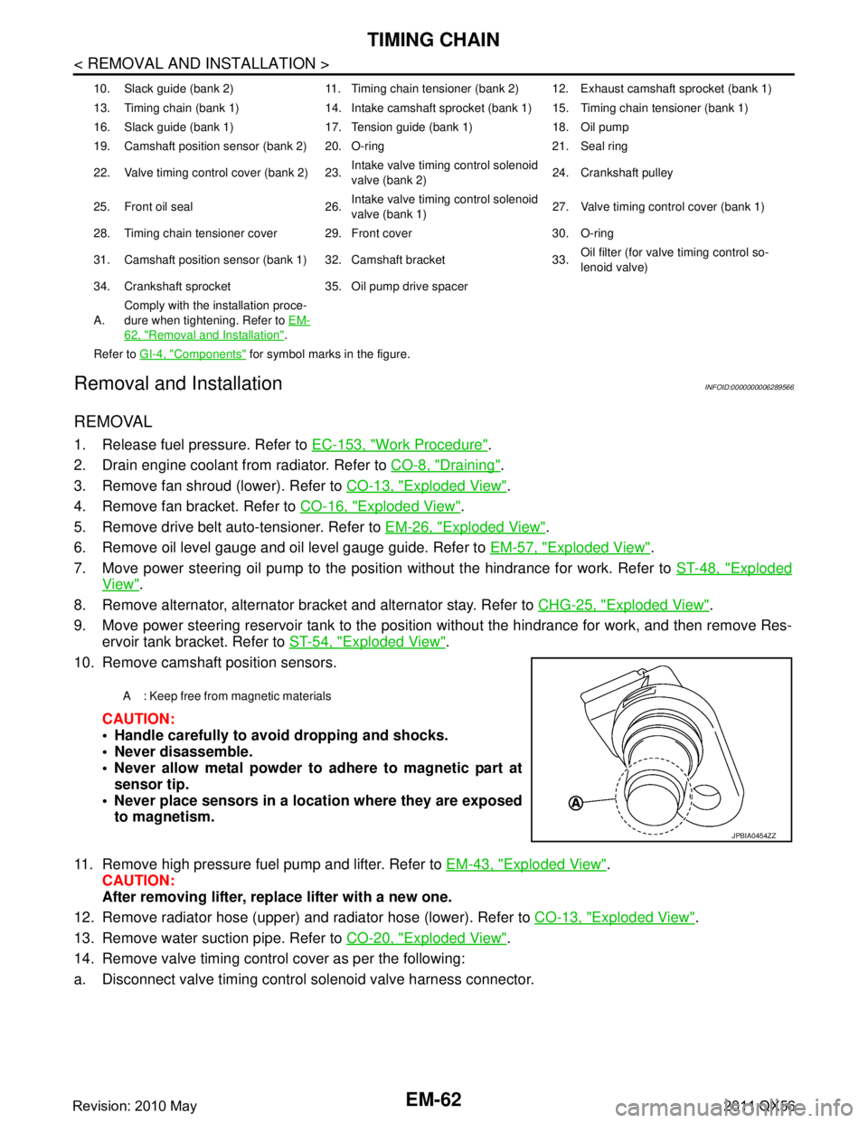
10. Remove camshaft position sensors.
CAUTION:
Handle carefully to avoid dropping and shocks.
Never disassemble.
Never allow metal powder to adhere to magnetic part atsensor tip.
Never place sensors in a lo cation where they are exposed
to magnetism.
11. Remove high pressure fuel pump and lifter. Refer to EM-43, "
Exploded View".
CAUTION:
After removing lifter, replace lifter with a new one.
12. Remove radiator hose (upper) and radiator hose (lower). Refer to CO-13, "
Exploded View".
13. Remove water suction pipe. Refer to CO-20, "
Exploded View".
14. Remove valve timing control cover as per the following:
a. Disconnect valve timing control solenoid valve harness connector.
10. Slack guide (bank 2) 11. Timing chain tensioner (bank 2) 12. Exhaust camshaft sprocket (bank 1)
13. Timing chain (bank 1) 14. Intake camshaft sprocket (bank 1) 15. Timing chain tensioner (bank 1)
16. Slack guide (bank 1) 17. Tension guide (bank 1) 18. Oil pump
19. Camshaft position sensor (bank 2) 20. O-ring 21. Seal ring
22. Valve timing control cover (bank 2) 23. Intake valve timing control solenoid
valve (bank 2)24. Crankshaft pulley
25. Front oil seal 26. Intake valve timing control solenoid
valve (bank 1)27. Valve timing control cover (bank 1)
28. Timing chain tensioner cover 29. Front cover 30. O-ring
31. Camshaft position sensor (bank 1) 32. Camshaft bracket 33. Oil filter (for valve timing control so-
lenoid valve)
34. Crankshaft sprocket 35. Oil pump drive spacer
A. Comply with the installation proce-
dure when tightening. Refer to
EM-
62, "Removal and Installation".
Refer to GI-4, "
Components" for symbol marks in the figure.
A : Keep free from magnetic materials
JPBIA0454ZZ
Revision: 2010 May2011 QX56
Page 3666 of 5598

OIL PUMPLU-13
< REMOVAL AND INSTALLATION >
C
DE
F
G H
I
J
K L
M A
LU
NP
O
OIL PUMP
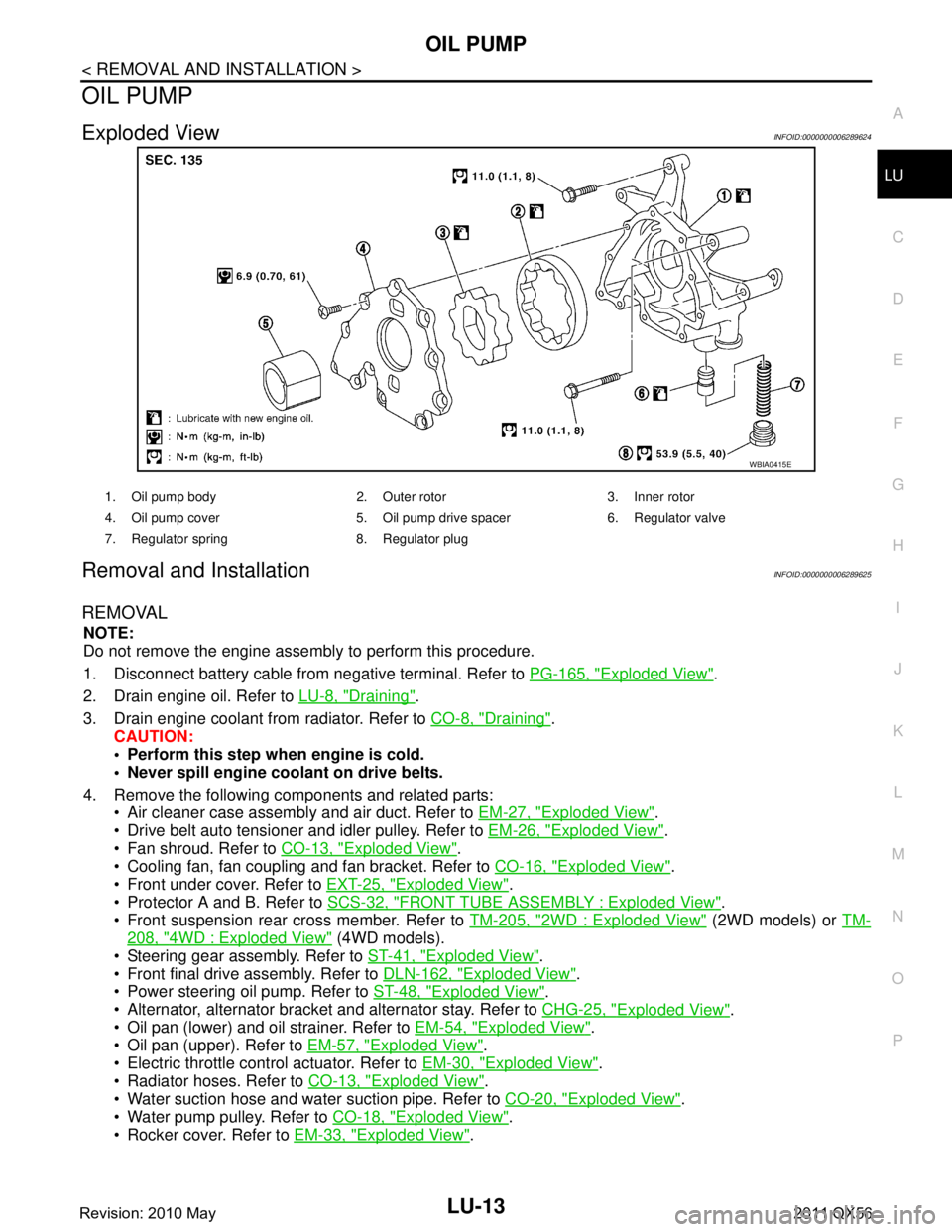
Exploded ViewINFOID:0000000006289624
Removal and InstallationINFOID:0000000006289625
REMOVAL
NOTE:
Do not remove the engine assembly to perform this procedure.
1. Disconnect battery cable from
negative terminal. Refer to PG-165, "
Exploded View".
2. Drain engine oil. Refer to LU-8, "
Draining".
3. Drain engine coolant from radiator. Refer to CO-8, "
Draining".
CAUTION:
Perform this step when engine is cold.
Never spill engine coolant on drive belts.
4. Remove the following components and related parts: Air cleaner case assembly and air duct. Refer to EM-27, "
Exploded View".
Drive belt auto tensioner and idler pulley. Refer to EM-26, "
Exploded View".
Fan shroud. Refer to CO-13, "
Exploded View".
Cooling fan, fan coupling and fan bracket. Refer to CO-16, "
Exploded View".
Front under cover. Refer to EXT-25, "
Exploded View".
Protector A and B. Refer to SCS-32, "
FRONT TUBE ASSEMBLY : Exploded View".
Front suspension rear cross member. Refer to TM-205, "
2WD : Exploded View" (2WD models) or TM-
208, "4WD : Exploded View" (4WD models).
Steering gear assembly. Refer to ST-41, "
Exploded View".
Front final drive assembly. Refer to DLN-162, "
Exploded View".
Power steering oil pump. Refer to ST-48, "
Exploded View".
Alternator, alternator bracket and alternator stay. Refer to CHG-25, "
Exploded View".
Oil pan (lower) and oil strainer. Refer to EM-54, "
Exploded View".
Oil pan (upper). Refer to EM-57, "
Exploded View".
Electric throttle control actuator. Refer to EM-30, "
Exploded View".
Radiator hoses. Refer to CO-13, "
Exploded View".
Water suction hose and water suction pipe. Refer to CO-20, "
Exploded View".
Water pump pulley. Refer to CO-18, "
Exploded View".
Rocker cover. Refer to EM-33, "
Exploded View".
WBIA0415E
1. Oil pump body 2. Outer rotor 3. Inner rotor
4. Oil pump cover 5. Oil pump drive spacer 6. Regulator valve
7. Regulator spring 8. Regulator plug
Revision: 2010 May2011 QX56