2011 INFINITI QX56 Idler pulley
[x] Cancel search: Idler pulleyPage 958 of 5598

CO-16
< REMOVAL AND INSTALLATION >
COOLING FAN
COOLING FAN
Exploded ViewINFOID:0000000006289666
Removal and InstallationINFOID:0000000006289667
REMOVAL
1. Remove front under cover with power tool. Refer to EXT-25, "Exploded View".
2. Remove fan shroud (lower). Refer to CO-13, "
Exploded View".
3. Move reservoir tank to the position without the hindrance for work, refer to following.
Remove fixed bolts
Remove reservoir tank hose clamp.
4. Remove radiator core support cover. Refer to DLK-220, "
Exploded View".
5. Remove fan shroud (upper), refer to following. Remove EVAP hose.
Remove fan shroud (upper) mounting bolts. Refer to CO-13, "
Exploded View".
Move air cleaner to the position without the hindrance for work.
Remove engine cover. Refer to EM-25, "
Exploded View".
6. Remove cooling fan.
7. Remove drive belt. Refer to EM-20, "
Exploded View".
8. Disconnect fan coupling harness connector.
9. Remove fan coupling.
10. Remove bracket.
11. Remove cooling fan pulley.
12. Remove Idler pulley.
1. Fan bracket 2. Cooling fan pulley 3. Fan coupling
4. Bracket 5. Cooling fan
Refer to GI-4, "
Components" for symbols not described on the above.
JPBIA3326GB
Revision: 2010 May2011 QX56
Page 2563 of 5598
EM-1
ENGINE
C
DE
F
G H
I
J
K L
M
SECTION EM
A
EM
N
O P
CONTENTS
ENGINE MECHANICAL
PRECAUTION ................ ...............................3
PRECAUTIONS .............................................. .....3
Precaution for Procedure without Cowl Top Cover ......3
Precaution for Supplemental Restraint System
(SRS) "AIR BAG" and "SEAT BELT PRE-TEN-
SIONER" ...................................................................
3
Precaution Necessary for Steering Wheel Rota-
tion after Battery Disconnect .....................................
3
Precaution for Drain Engine Coolant and Engine
Oil ..............................................................................
4
Precaution for Disconnecting Fuel Piping .................4
Precaution for Handling High Pressure Fuel Sys-
tem ............................................................................
4
Precaution for Removal and Disassembly ................4
Precaution for Inspection, Repair and Replace-
ment ..........................................................................
4
Precaution for Assembly and Installation ..................4
Parts Requiring Angle Tightening .............................5
Precaution for Liquid Gasket .....................................5
Definitions of Bank Names ........................................6
PREPARATION ............................................7
PREPARATION .............................................. .....7
Special Service Tool ........................................... ......7
Commercial Service Tool ..........................................9
BASIC INSPECTION ...................................12
CAMSHAFT VALVE CLEARANCE ............... ....12
Inspection ............................................................ ....12
COMPRESSION PRESSURE ............................16
Inspection ............................................................ ....16
SYMPTOM DIAGNOSIS ..............................18
NOISE, VIBRATION AND HARSHNESS
(NVH) TROUBLESHOOTING ........................ ....
18
NVH Troubleshooting - Engine Noise .............. ....18
Use the Chart Below to Help You Find the C
ause of the Symptom ........................................ ....
19
PERIODIC MAINTENANCE ........................20
DRIVE BELTS ...................................................20
Exploded View ..................................................... ....20
Checking ..................................................................20
Tension Adjustment ................................................20
Removal and Installation .........................................20
Inspection ................................................................21
AIR CLEANER FILTER .....................................22
Exploded View .........................................................22
Removal and Installation .........................................22
SPARK PLUG ...................................................23
Exploded View .........................................................23
Removal and Installation .........................................23
Inspection ................................................................24
REMOVAL AND INSTALLATION ...............25
ENGINE COVER ...............................................25
Exploded View ..................................................... ....25
Removal and Installation .........................................25
DRIVE BELT AUTO TENSIONER AND IDLER
PULLEY .............................................................
26
Exploded View .........................................................26
Removal and Installation .........................................26
AIR CLEANER AND AIR DUCT .......................27
Exploded View .........................................................27
Removal and Installation .........................................27
Inspection ................................................................28
IGNITION COIL .................................................29
Exploded View .........................................................29
Removal and Installation .........................................29
INTAKE MANIFOLD .........................................30
Exploded View .........................................................30
Revision: 2010 May2011 QX56
Page 2581 of 5598
NOISE, VIBRATION AND HARSHNESS (NVH) TROUBLESHOOTINGEM-19
< SYMPTOM DIAGNOSIS >
C
DE
F
G H
I
J
K L
M A
EM
NP
O
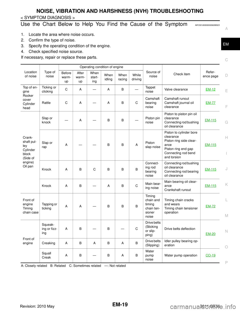
Use the Chart Below to Help You Find the Cause of the SymptomINFOID:0000000006289523
1. Locate the area where noise occurs.
2. Confirm the type of noise.
3. Specify the operating condition of the engine.
4. Check specified noise source.
If necessary, repair or replace these parts.
A: Closely related B: Related C: Sometimes related —: Not related Location
of noise Type of
noise Operating condition of engine
Source of noise Check item Refer-
ence page
Before
warm- up After
warm- up When
start- ing When
idling When
racing While
driving
Top of en-
gine
Rocker
cover
Cylinder
head Ticking or
clicking
CA—AB— Tappet
noiseValve clearance
EM-12
Rattle C A — A B C Camshaft
bearing
noiseCamshaft runout
Camshaft journal oil
clearance
EM-77
Crank-
shaft pul-
ley
Cylinder
block
(Side of
engine)
Oil panSlap or
knock
—A—B B—
Piston pin
noisePiston to piston pin oil
clearance
Connecting rod bushing
oil clearance
EM-115
Slap or
rap
A——B B A
Piston
slap noisePiston to cylinder bore
clearance
Piston ring side clear-
ance
Piston ring end gap
Connecting rod bend
and torsion
EM-115
Knock A B C B B B
Connect-
ing rod
bearing
noiseConnecting rod bushing
oil clearance
Connecting rod bearing
oil clearance
EM-115
Knock A B — A B C
Main bear-
ing noiseMain bearing oil clear-
ance
Crankshaft runout
EM-115
Front of
engine
Timing
chain caseTapping or
ticking
AA—BBB Timing
chain and
timing
chain ten-
sioner
noiseTiming chain cracks
and wears
Timing chain tensioner
operation
EM-72
Front of
engineSqueak-
ing or fizz-
ing
AB—B—C Drive belts
(Sticking
or slip-
ping)Drive belts deflection
EM-20
CreakingABABAB Drive belts
(Slipping)Idler pulley bearing op-
eration
Squall
Creak AB—BAB Water
pump
noiseWater pump operation
CO-19
Revision: 2010 May2011 QX56
Page 2582 of 5598
EM-20
< PERIODIC MAINTENANCE >
DRIVE BELTS
PERIODIC MAINTENANCE
DRIVE BELTS
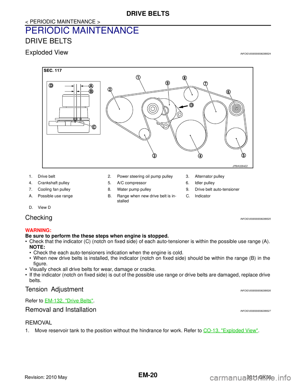
Exploded ViewINFOID:0000000006289524
CheckingINFOID:0000000006289525
WARNING:
Be sure to perform the these steps when engine is stopped.
Check that the indicator (C) (notch on fixed side) of each auto-tensioner is within the possible use range (A).
NOTE:
Check the each auto-tensioners indication when the engine is cold.
When new drive belts is installed, the indicator (notch on fixed side) should be within the range (B) in the\
figure.
Visually check all drive belts for wear, damage or cracks.
If the indicator (notch on fixed side) is out of the possible use range or drive belts are damaged, replace drive
belts.
Tension AdjustmentINFOID:0000000006289526
Refer to EM-132, "Drive Belts".
Removal and InstallationINFOID:0000000006289527
REMOVAL
1. Move reservoir tank to the position without the hindrance for work. Refer to CO-13, "Exploded View".
1. Drive belt 2. Power steering oil pump pulley 3. Alternator pulley
4. Crankshaft pulley 5. A/C compressor 6. Idler pulley
7. Cooling fan pulley 8. Water pump pulley 9. Drive belt auto-tensioner
A. Possible use range B. Range when new drive belt is in-
stalledC. Indicator
D. View D
JPBIA3264ZZ
Revision: 2010 May2011 QX56
Page 2588 of 5598
EM-26
< REMOVAL AND INSTALLATION >
DRIVE BELT AUTO TENSIONER AND IDLER PULLEY
DRIVE BELT AUTO TENSI ONER AND IDLER PULLEY
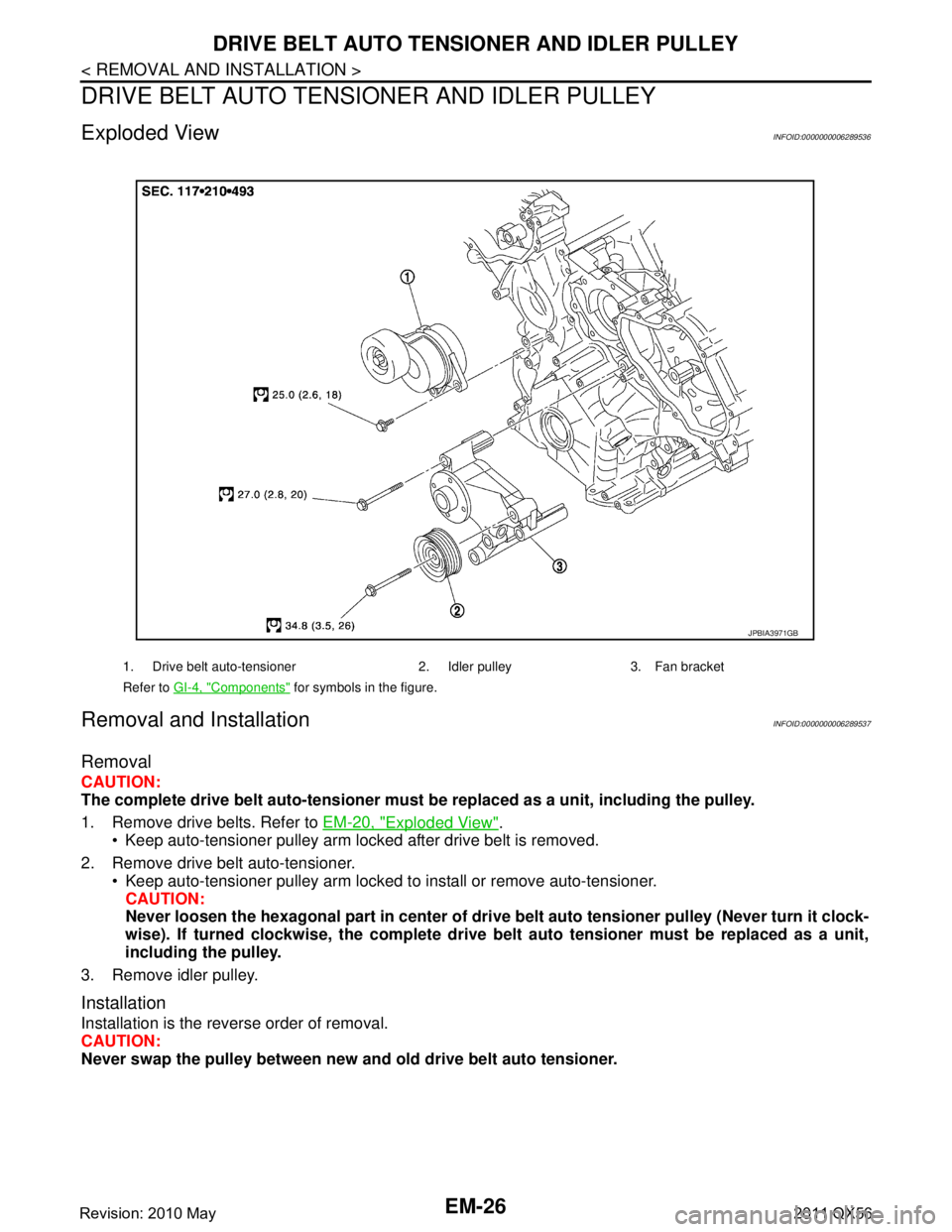
Exploded ViewINFOID:0000000006289536
Removal and InstallationINFOID:0000000006289537
Removal
CAUTION:
The complete drive belt auto-tensioner must be replaced as a unit, including the pulley.
1. Remove drive belts. Refer to EM-20, "
Exploded View".
Keep auto-tensioner pulley arm locked after drive belt is removed.
2. Remove drive belt auto-tensioner. Keep auto-tensioner pulley arm locked to install or remove auto-tensioner.CAUTION:
Never loosen the hexagonal part in center of dri ve belt auto tensioner pulley (Never turn it clock-
wise). If turned clockwise, the complete drive belt auto tensioner must be replaced as a unit,
including the pulley.
3. Remove idler pulley.
Installation
Installation is the reverse order of removal.
CAUTION:
Never swap the pulley between new an d old drive belt auto tensioner.
1. Drive belt auto-tensioner 2. Idler pulley 3. Fan bracket
Refer to GI-4, "
Components" for symbols in the figure.
JPBIA3971GB
Revision: 2010 May2011 QX56
Page 2646 of 5598
EM-84
< REMOVAL AND INSTALLATION >
CAMSHAFT
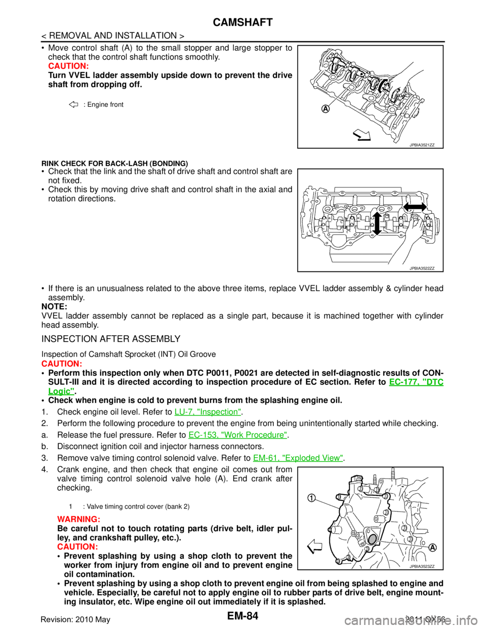
Move control shaft (A) to the small stopper and large stopper tocheck that the control shaft functions smoothly.
CAUTION:
Turn VVEL ladder assembly upside down to prevent the drive
shaft from dropping off.
RINK CHECK FOR BACK-LASH (BONDING) Check that the link and the shaft of drive shaft and control shaft are
not fixed.
Check this by moving drive shaft and control shaft in the axial and
rotation directions.
If there is an unusualness related to the above three items, replace VVEL ladder assembly & cylinder head
assembly.
NOTE:
VVEL ladder assembly cannot be replaced as a singl e part, because it is machined together with cylinder
head assembly.
INSPECTION AFTER ASSEMBLY
Inspection of Camshaft Sprocket (INT) Oil Groove
CAUTION:
Perform this inspection only when DTC P0011, P 0021 are detected in self-diagnostic results of CON-
SULT-III and it is directed according to inspection procedure of EC section. Refer to EC-177, "
DTC
Logic".
Check when engine is cold to prevent burns from the splashing engine oil.
1. Check engine oil level. Refer to LU-7, "
Inspection".
2. Perform the following procedure to prevent the engine from being unintentionally started while checking.
a. Release the fuel pressure. Refer to EC-153, "
Work Procedure".
b. Disconnect ignition coil and injector harness connectors.
3. Remove valve timing control solenoid valve. Refer to EM-61, "
Exploded View".
4. Crank engine, and then check that engine oil comes out from valve timing control solenoid valve hole (A). End crank after
checking.
WARNING:
Be careful not to touch rotati ng parts (drive belt, idler pul-
ley, and crankshaft pulley, etc.).
CAUTION:
Prevent splashing by using a shop cloth to prevent the worker from injury from en gine oil and to prevent engine
oil contamination.
Prevent splashing by using a shop cloth to prevent engine oil from being splashed to engine and
vehicle. Especially, be careful not to apply engine oil to rubber parts of drive belt, engine mount-
ing insulator, etc. Wipe engine oil out immediately if it is splashed.
: Engine front
JPBIA3521ZZ
JPBIA3522ZZ
1 : Valve timing control cover (bank 2)
JPBIA3523ZZ
Revision: 2010 May2011 QX56
Page 3666 of 5598
OIL PUMPLU-13
< REMOVAL AND INSTALLATION >
C
DE
F
G H
I
J
K L
M A
LU
NP
O
OIL PUMP
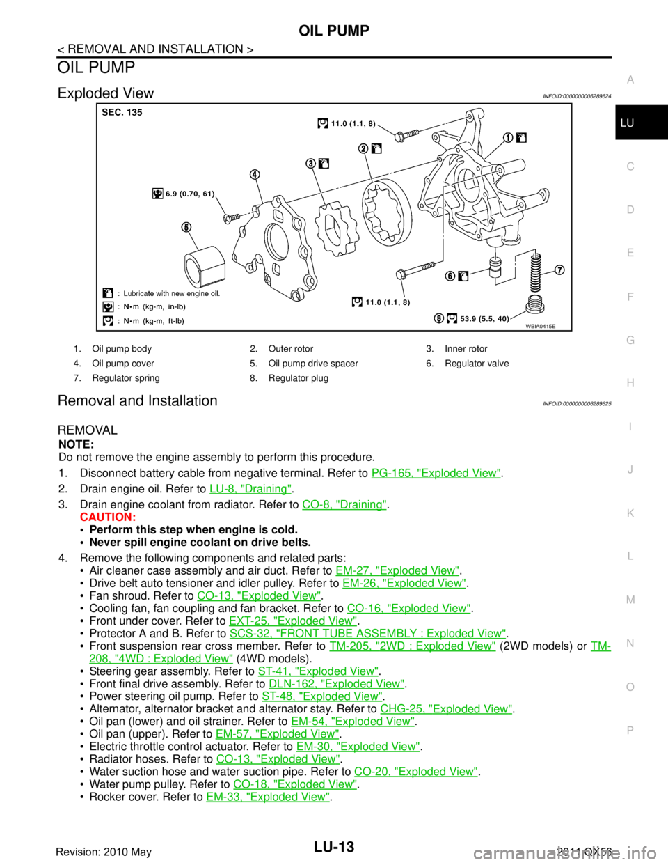
Exploded ViewINFOID:0000000006289624
Removal and InstallationINFOID:0000000006289625
REMOVAL
NOTE:
Do not remove the engine assembly to perform this procedure.
1. Disconnect battery cable from
negative terminal. Refer to PG-165, "
Exploded View".
2. Drain engine oil. Refer to LU-8, "
Draining".
3. Drain engine coolant from radiator. Refer to CO-8, "
Draining".
CAUTION:
Perform this step when engine is cold.
Never spill engine coolant on drive belts.
4. Remove the following components and related parts: Air cleaner case assembly and air duct. Refer to EM-27, "
Exploded View".
Drive belt auto tensioner and idler pulley. Refer to EM-26, "
Exploded View".
Fan shroud. Refer to CO-13, "
Exploded View".
Cooling fan, fan coupling and fan bracket. Refer to CO-16, "
Exploded View".
Front under cover. Refer to EXT-25, "
Exploded View".
Protector A and B. Refer to SCS-32, "
FRONT TUBE ASSEMBLY : Exploded View".
Front suspension rear cross member. Refer to TM-205, "
2WD : Exploded View" (2WD models) or TM-
208, "4WD : Exploded View" (4WD models).
Steering gear assembly. Refer to ST-41, "
Exploded View".
Front final drive assembly. Refer to DLN-162, "
Exploded View".
Power steering oil pump. Refer to ST-48, "
Exploded View".
Alternator, alternator bracket and alternator stay. Refer to CHG-25, "
Exploded View".
Oil pan (lower) and oil strainer. Refer to EM-54, "
Exploded View".
Oil pan (upper). Refer to EM-57, "
Exploded View".
Electric throttle control actuator. Refer to EM-30, "
Exploded View".
Radiator hoses. Refer to CO-13, "
Exploded View".
Water suction hose and water suction pipe. Refer to CO-20, "
Exploded View".
Water pump pulley. Refer to CO-18, "
Exploded View".
Rocker cover. Refer to EM-33, "
Exploded View".
WBIA0415E
1. Oil pump body 2. Outer rotor 3. Inner rotor
4. Oil pump cover 5. Oil pump drive spacer 6. Regulator valve
7. Regulator spring 8. Regulator plug
Revision: 2010 May2011 QX56
Page 3682 of 5598
MA-12
< PERIODIC MAINTENANCE >
ENGINE MAINTENANCE
ENGINE MAINTENANCE
DRIVE BELTS
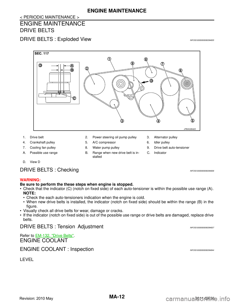
DRIVE BELTS : Exploded ViewINFOID:0000000006394835
DRIVE BELTS : CheckingINFOID:0000000006394836
WARNING:
Be sure to perform the these steps when engine is stopped.
Check that the indicator (C) (notch on fixed side) of each auto-tensioner is within the possible use range (A).
NOTE:
Check the each auto-tensioners indication when the engine is cold.
When new drive belts is installed, the indicator (notch on fixed side) should be within the range (B) in the\
figure.
Visually check all drive belts for wear, damage or cracks.
If the indicator (notch on fixed side) is out of the possible use range or drive belts are damaged, replace drive
belts.
DRIVE BELTS : Tension AdjustmentINFOID:0000000006394837
Refer to EM-132, "Drive Belts".
ENGINE COOLANT
ENGINE COOLANT : InspectionINFOID:0000000006394844
LEVEL
1. Drive belt 2. Power steering oil pump pulley 3. Alternator pulley
4. Crankshaft pulley 5. A/C compressor 6. Idler pulley
7. Cooling fan pulley 8. Water pump pulley 9. Drive belt auto-tensioner
A. Possible use range B. Range when new drive belt is in-
stalledC. Indicator
D. View D
JPBIA3264ZZ
Revision: 2010 May2011 QX56