2011 INFINITI QX56 ground
[x] Cancel search: groundPage 2823 of 5598
![INFINITI QX56 2011 Factory Service Manual
EXTERIOR LIGHTING SYSTEM SYMPTOMSEXL-113
< SYMPTOM DIAGNOSIS > [XENON TYPE]
C
D
E
F
G H
I
J
K
M A
B
EXL
N
O P
SYMPTOM DIAGNOSIS
EXTERIOR LIGHTING SYSTEM SYMPTOMS
Symptom TableINFOID:0000000006213980 INFINITI QX56 2011 Factory Service Manual
EXTERIOR LIGHTING SYSTEM SYMPTOMSEXL-113
< SYMPTOM DIAGNOSIS > [XENON TYPE]
C
D
E
F
G H
I
J
K
M A
B
EXL
N
O P
SYMPTOM DIAGNOSIS
EXTERIOR LIGHTING SYSTEM SYMPTOMS
Symptom TableINFOID:0000000006213980](/manual-img/42/57033/w960_57033-2822.png)
EXTERIOR LIGHTING SYSTEM SYMPTOMSEXL-113
< SYMPTOM DIAGNOSIS > [XENON TYPE]
C
D
E
F
G H
I
J
K
M A
B
EXL
N
O P
SYMPTOM DIAGNOSIS
EXTERIOR LIGHTING SYSTEM SYMPTOMS
Symptom TableINFOID:0000000006213980
CAUTION:
Perform the self-diagnosis with CONS ULT-III before the symptom diagnosis. Perform the trouble diag-
nosis if any DTC is detected.
Symptom Possible cause Inspection item
Headlamp does not
switch to the high beam. One sideFuse
Harness between IPDM E/R
and the front combination lamp
Front combination lamp
(High beam solenoid)
IPDM E/R
Harness between the front com- bination lamp and ground Headlamp (HI) circuit
Refer to
EXL-86, "
Component
Function Check".
Both sides Symptom diagnosis
“BOTH SIDE HEADLAMPS DO NOT SWITCH TO HIGH BEAM”
Refer to
EXL-117, "
Diagnosis Procedure".
High beam indicator lamp is not turned ON.
[Headlamp (HI) is turned ON.] Combination meter Combination meter
Data monitor “HI-BEAM IND”
BCM (HEAD LAMP) Active test “HEADLAMP”
Headlamp does not
switch to the low beam. One side
Front combination lamp (High
beam solenoid) —
Both sides Combination switch
Harness between the combina-
tion switch and BCM
BCM Combination switch
Refer to
BCS-80, "
Symptom Table".
High beam request signal
BCM
IPDM E/R IPDM E/R
Data monitor “HL HI REQ”
IPDM E/R —
Headlamp is not turned
ON. One sideFuse
Xenon bulb
Harness between IPDM E/R
and the front combination lamp
Front combination lamp (xenon
headlamp)
IPDM E/R
Harness between the front com- bination lamp and ground Headlamp (L
O) circuit
Refer to EXL-88, "
Component
Function Check".
Both sides Symptom diagnosis
“BOTH SIDE HEADLAMPS (LO) ARE NOT TURNED ON”
Refer to EXL-118, "
Diagnosis Procedure".
Headlamp is not turned
OFF. When the ignition
switch is turned ON
The ignition switch is
turned OFF (After acti-
vating the battery sav-
er).
IPDM E/R —
Revision: 2010 May2011 QX56
Page 2825 of 5598
![INFINITI QX56 2011 Factory Service Manual
EXTERIOR LIGHTING SYSTEM SYMPTOMSEXL-115
< SYMPTOM DIAGNOSIS > [XENON TYPE]
C
D
E
F
G H
I
J
K
M A
B
EXL
N
O P
Turn signal indicator lamp
does not blink.
(Turn signal i lamp is nor-
mal.) One side Co INFINITI QX56 2011 Factory Service Manual
EXTERIOR LIGHTING SYSTEM SYMPTOMSEXL-115
< SYMPTOM DIAGNOSIS > [XENON TYPE]
C
D
E
F
G H
I
J
K
M A
B
EXL
N
O P
Turn signal indicator lamp
does not blink.
(Turn signal i lamp is nor-
mal.) One side Co](/manual-img/42/57033/w960_57033-2824.png)
EXTERIOR LIGHTING SYSTEM SYMPTOMSEXL-115
< SYMPTOM DIAGNOSIS > [XENON TYPE]
C
D
E
F
G H
I
J
K
M A
B
EXL
N
O P
Turn signal indicator lamp
does not blink.
(Turn signal i lamp is nor-
mal.) One side Combination meter —
Both sides
(Always)
Turn signal indicator lamp sig-
nal
-BCM
Combination meter Combination meter
Data monitor “TURN IND”
BCM (FLASHER) Active test “FLASHER”
Both sides
(Only when activating
hazard warn ing lamp
with the ignition switch
OFF) Combination meter power sup-
ply and ground circuit
Combination meter Combination meter
Power supply and ground circuit
Refer to
MWI-64, "
COMBINATION
METER : Diagnosis Procedure".
Hazard warning lamp does not activate.
Hazard warning lamp continues activating.
(Turn signal is normal.) Hazard switch
Harness between hazard
switch and BCM
BCM Hazard switch
Refer to
EXL-105, "
Component
Function Check".
AFS control does not activate. Harness between AFS control
unit and AFS switch.
AFS control unit AFS switch
Refer to
EXL-107, "
Component
Function Check".
Headlamp auto aiming does not activate.
(AFS is normal.) Harness between AFS control
unit and aiming motor
Front combination lamp (Aiming motor)
AFS control unit Headlamp levelizer circuit
Refer to
EXL-91, "
Component
Function Check".
AFS OFF indicator lamp is not turned ON. AFS OFF indicator lamp signal
- Combination meter
- AFS control unit
Combination meterCombination meter
Data monitor “AFS OFF IND”
Symptom Possible cause Inspection item
Revision: 2010 May2011 QX56
Page 2934 of 5598
FUEL LEVEL SENSOR UNIT, FUEL FILTER AND FUEL PUMP ASSEMBLY
FL-5
< REMOVAL AND INSTALLATION >
C
D E
F
G H
I
J
K L
M A
FL
NP
O
REMOVAL AND INSTALLATION
FUEL LEVEL SENSOR UNIT, FUEL FI
LTER AND FUEL PUMP ASSEMBLY
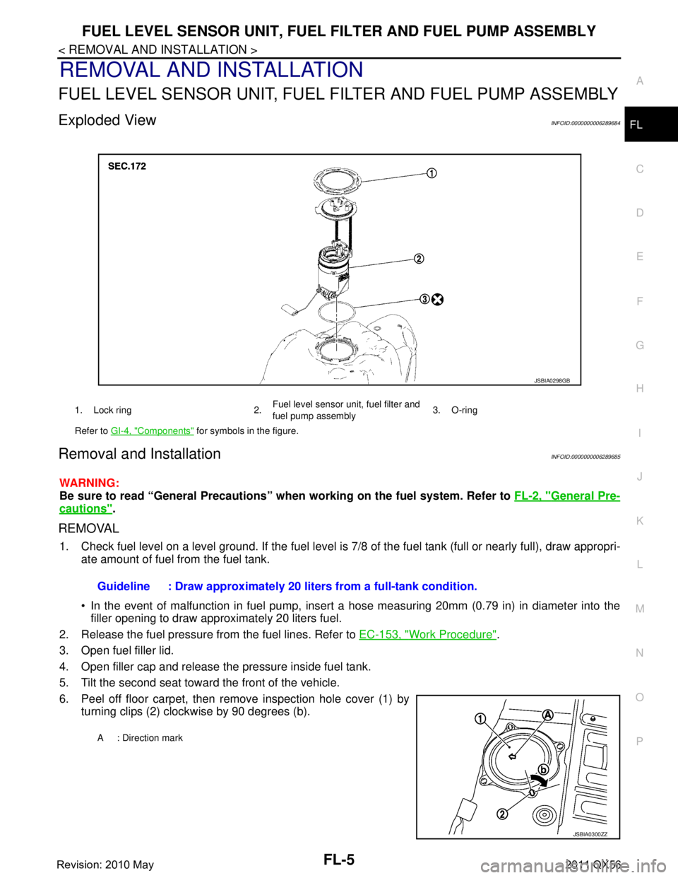
Exploded ViewINFOID:0000000006289684
Removal and InstallationINFOID:0000000006289685
WARNING:
Be sure to read “General Precautions” wh en working on the fuel system. Refer to FL-2, "
General Pre-
cautions".
REMOVAL
1. Check fuel level on a level ground. If the fuel level is 7/8 of the fuel tank (full or nearly full), draw appropri-
ate amount of fuel from the fuel tank.
In the event of malfunction in fuel pump, insert a hose measuring 20mm (0.79 in) in diameter into the
filler opening to draw approximately 20 liters fuel.
2. Release the fuel pressure from the fuel lines. Refer to EC-153, "
Work Procedure".
3. Open fuel filler lid.
4. Open filler cap and release the pressure inside fuel tank.
5. Tilt the second seat toward the front of the vehicle.
6. Peel off floor carpet, then remove inspection hole cover (1) by turning clips (2) clockwise by 90 degrees (b).
1. Lock ring 2. Fuel level sensor unit, fuel filter and
fuel pump assembly3. O-ring
Refer to GI-4, "
Components" for symbols in the figure.
JSBIA0298GB
Guideline : Draw approximately 20 li ters from a full-tank condition.
A : Direction mark
JSBIA0300ZZ
Revision: 2010 May2011 QX56
Page 2937 of 5598
FL-8
< REMOVAL AND INSTALLATION >
FUEL TANK
FUEL TANK
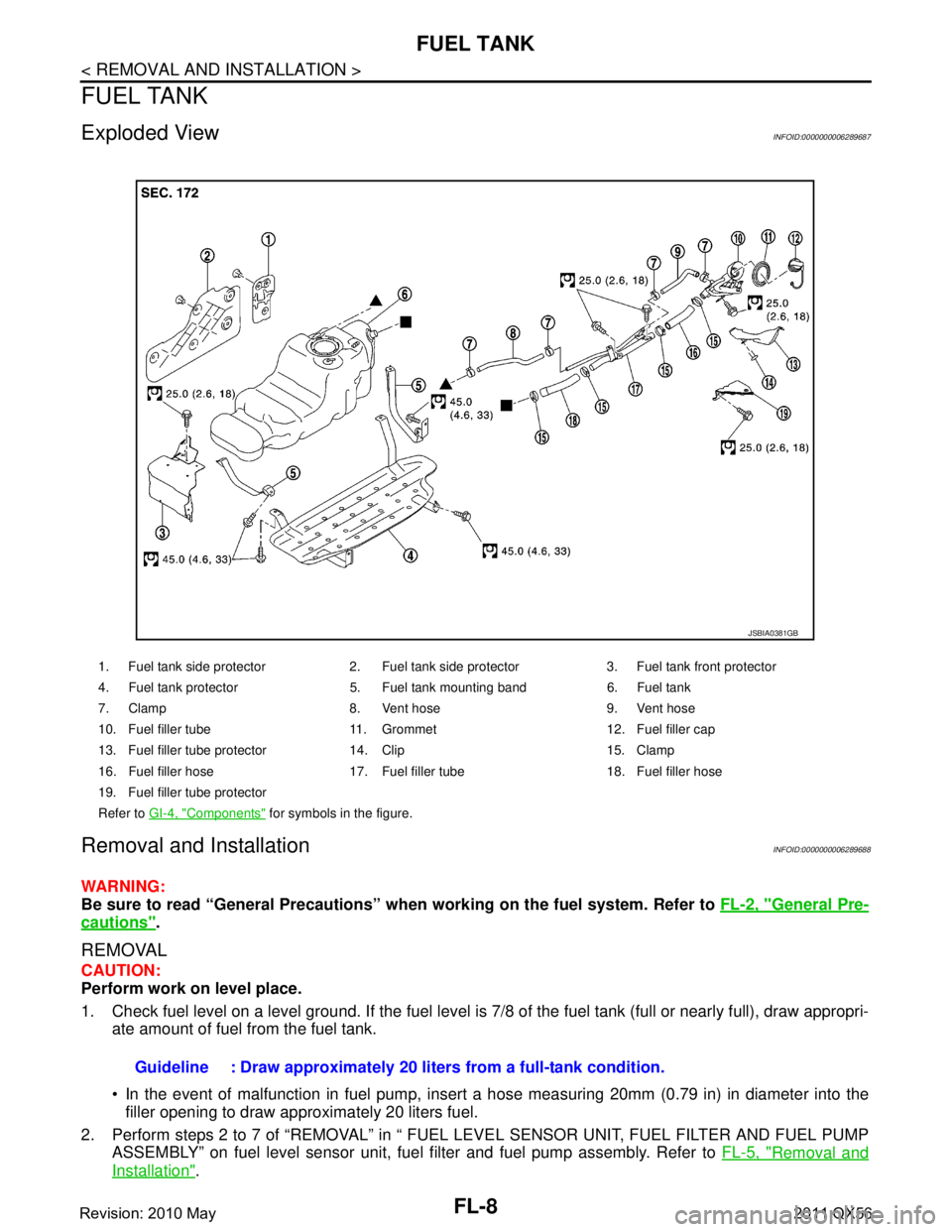
Exploded ViewINFOID:0000000006289687
Removal and InstallationINFOID:0000000006289688
WARNING:
Be sure to read “General Precautions” when working on the fuel system. Refer to FL-2, "
General Pre-
cautions".
REMOVAL
CAUTION:
Perform work on level place.
1. Check fuel level on a level ground. If the fuel level is 7/8 of the fuel tank (full or nearly full), draw appropri-
ate amount of fuel from the fuel tank.
In the event of malfunction in fuel pump, insert a hose measuring 20mm (0.79 in) in diameter into the
filler opening to draw approximately 20 liters fuel.
2. Perform steps 2 to 7 of “REMOVAL” in “ FUEL LEVEL SENSOR UNIT, FUEL FILTER AND FUEL PUMP ASSEMBLY” on fuel level sensor unit, fuel filter and fuel pump assembly. Refer to FL-5, "
Removal and
Installation".
1. Fuel tank side protector 2. Fuel tank side protector 3. Fuel tank front protector
4. Fuel tank protector 5. Fuel tank mounting band 6. Fuel tank
7. Clamp 8. Vent hose 9. Vent hose
10. Fuel filler tube 11. Grommet 12. Fuel filler cap
13. Fuel filler tube protector 14. Clip 15. Clamp
16. Fuel filler hose 17. Fuel filler tube 18. Fuel filler hose
19. Fuel filler tube protector
Refer to GI-4, "
Components" for symbols in the figure.
JSBIA0381GB
Guideline : Draw approximately 20 li ters from a full-tank condition.
Revision: 2010 May2011 QX56
Page 2945 of 5598
PRECAUTIONSFSU-3
< PRECAUTION >
C
DF
G H
I
J
K L
M A
B
FSU
N
O P
5. When the repair work is completed, re-connect both battery cables. With the brake pedal released, turn
the push-button ignition switch from ACC position to ON position, then to LOCK position. (The steering
wheel will lock when the push-button ignition switch is turned to LOCK position.)
6. Perform self-diagnosis check of a ll control units using CONSULT-III.
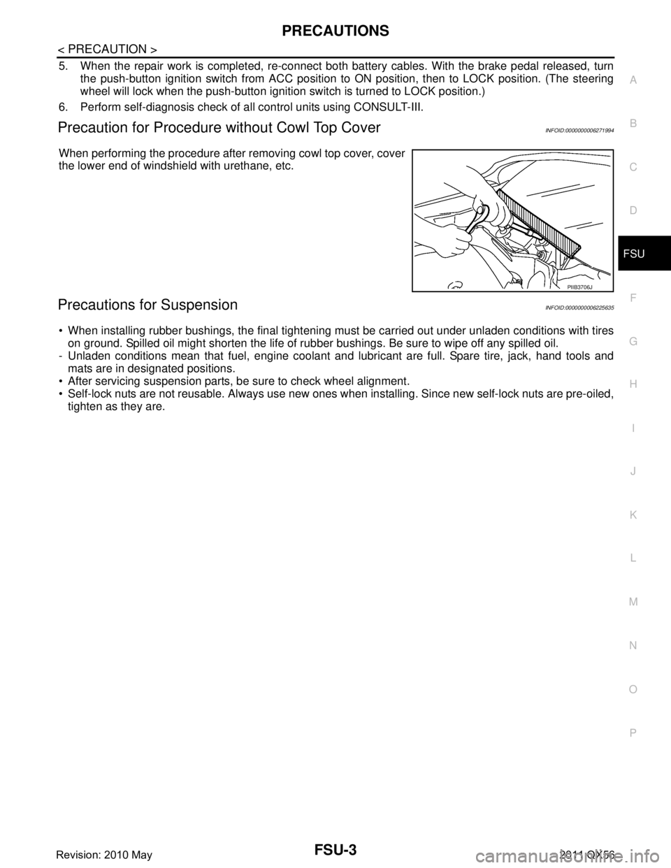
Precaution for Procedure without Cowl Top CoverINFOID:0000000006271994
When performing the procedure after removing cowl top cover, cover
the lower end of windshield with urethane, etc.
Precautions for SuspensionINFOID:0000000006225635
When installing rubber bushings, the final tightening mu st be carried out under unladen conditions with tires
on ground. Spilled oil might shorten the life of rubb er bushings. Be sure to wipe off any spilled oil.
- Unladen conditions mean that fuel, engine coolant and l ubricant are full. Spare tire, jack, hand tools and
mats are in designated positions.
After servicing suspension parts, be sure to check wheel alignment.
Self-lock nuts are not reusable. Always use new ones w hen installing. Since new self-lock nuts are pre-oiled,
tighten as they are.
PIIB3706J
Revision: 2010 May2011 QX56
Page 2948 of 5598
FSU-6
< PERIODIC MAINTENANCE >
FRONT SUSPENSION ASSEMBLY
PERIODIC MAINTENANCE
FRONT SUSPENSION ASSEMBLY
InspectionINFOID:0000000006225639
MOUNTING INSPECTION
Check the mounting conditions (looseness, backlash) of each component and component conditions (wear,
damage) are normal.
BALL JOINT AXIAL END PLAY
1. Set front wheels in a straight-ahead position.
2. Measure axial end play by playing and moving up/dow n with iron bar or equivalent between lower link or
upper link and steering knuckle.
CAUTION:
Never depress brake pedal when measuring.
Never perform with tires on level ground.
Be careful not to damage ball joint boot. Never damage the installation position by applying
excessive force.
Shock absorber
Check for oil leakage, damage. Replace it if necessary. Axial end play : Refer to
FSU-21, "
Ball Joint".
Revision: 2010 May2011 QX56
Page 2953 of 5598
FRONT COIL SPRING AND SHOCK ABSORBERFSU-11
< REMOVAL AND INSTALLATION >
C
DF
G H
I
J
K L
M A
B
FSU
N
O P
12. Separate drive shaft from steering knuckle. (4WD) Refer to FAX-22, "Removal and Installation".
13. Remove front tube assembly A and front tube asse mbly B from shock absorber. (With HBMC) Refer to
SCS-32, "
FRONT TUBE ASSEMBLY : Removal and Installation".
14. Remove shock absorber.
15. Perform inspection after removal. (With HBMC) Refer to FSU-12, "
Inspection and Adjustment".
INSTALLATION
Note the following, and install in the reverse order of removal.
Never tap on the ball joint cap of the stabilizer connecting rod with a hammer or a similar item when inserting
the stabilizer connecting rod into the lower link. (Without HBMC)
Perform final tightening of bolts and nuts at the shock absorber lower side (rubber bushing), under unladen
conditions with tires on level ground.
Perform inspection after installation. Refer to FSU-12, "
Inspection and Adjustment".
Perform adjustment after installation. (With HBMC) Refer to FSU-12, "
Inspection and Adjustment".
After replacing the shock absorber, always follow the disposal procedure to discard the shock absorber.
Refer to FSU-13, "
Disposal".
Disassembly and AssemblyINFOID:0000000006273960
CAUTION:
The shock absorber assembly can not be disassembled. (With HBMC)
DISASSEMBLY (WITHOUT HBMC)
CAUTION:
Never damage shock absorber piston rod wh en removing components from shock absorber.
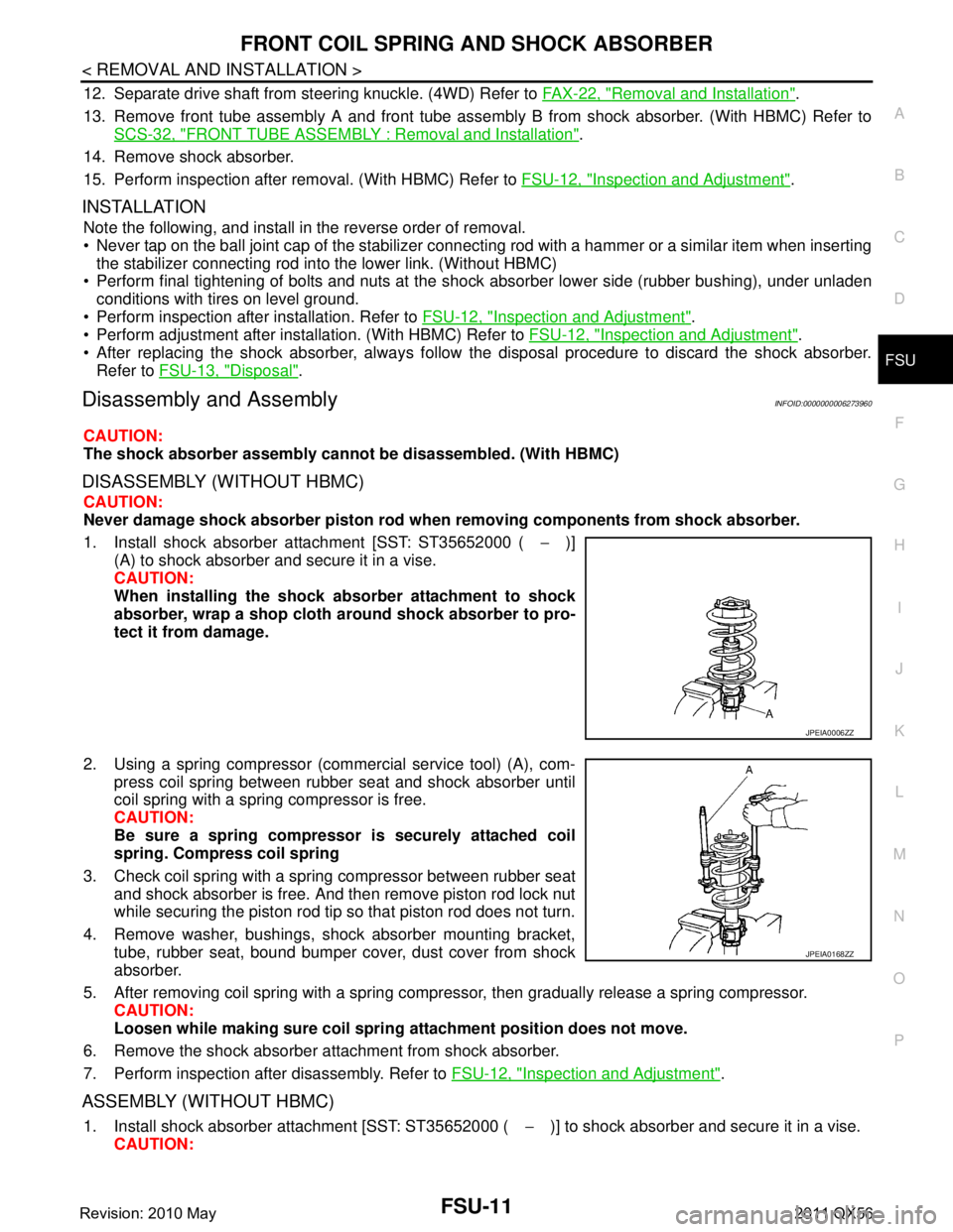
1. Install shock absorber attachment [SST: ST35652000 ( −)]
(A) to shock absorber and secure it in a vise.
CAUTION:
When installing the shock ab sorber attachment to shock
absorber, wrap a shop cloth around shock absorber to pro-
tect it from damage.
2. Using a spring compressor (commercial service tool) (A), com- press coil spring between rubber seat and shock absorber until
coil spring with a spring compressor is free.
CAUTION:
Be sure a spring compresso r is securely attached coil
spring. Compress coil spring
3. Check coil spring with a spring compressor between rubber seat and shock absorber is free. And then remove piston rod lock nut
while securing the piston rod tip so that piston rod does not turn.
4. Remove washer, bushings, shock absorber mounting bracket, tube, rubber seat, bound bumper cover, dust cover from shock
absorber.
5. After removing coil spring with a spring compressor, then gradually release a spring compressor. CAUTION:
Loosen while making sure coil spri ng attachment position does not move.
6. Remove the shock absorber at tachment from shock absorber.
7. Perform inspection after disassembly. Refer to FSU-12, "
Inspection and Adjustment".
ASSEMBLY (WITHOUT HBMC)
1. Install shock absorber attachment [SST: ST35652000 ( −)] to shock absorber and secure it in a vise.
CAUTION:
JPEIA0006ZZ
JPEIA0168ZZ
Revision: 2010 May2011 QX56
Page 2957 of 5598
LOWER LINKFSU-15
< REMOVAL AND INSTALLATION >
C
DF
G H
I
J
K L
M A
B
FSU
N
O P
12. Separate drive shaft from steering knuckle. (4WD) Refer to FAX-22, "Removal and Installation".
13. Remove lower link from steering knuckle. Refer to FA X - 8 , "
Removal and Installation" (2WD), FAX-18,
"Removal and Installation" (4WD).
14. Remove protector A. (With HBMC) Refer to SCS-32, "
FRONT TUBE ASSEMBLY : Removal and Installa-
tion".
15. Remove bracket. (With HBMC) Refer to SCS-32, "
FRONT TUBE ASSEMBLY : Removal and Installation".
16. Remove adjusting bolts, nuts, eccentric discs, stopper rubber, and lower link from vehicle.
17. Remove bump rubber from lower link.
18. Perform inspection after removal. Refer to FSU-15, "
Inspection".
INSTALLATION
Note the following, and install in the reverse order of removal.
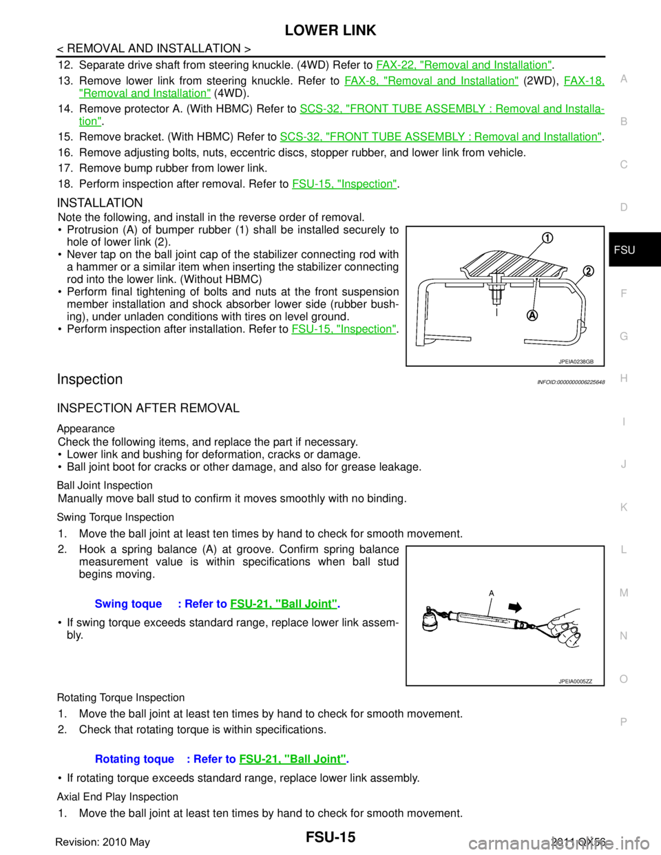
Protrusion (A) of bumper rubber (1) shall be installed securely to
hole of lower link (2).
Never tap on the ball joint cap of the stabilizer connecting rod with a hammer or a similar item when inserting the stabilizer connecting
rod into the lower link. (Without HBMC)
Perform final tightening of bolts and nuts at the front suspension member installation and shock absorber lower side (rubber bush-
ing), under unladen conditions with tires on level ground.
Perform inspection after installation. Refer to FSU-15, "
Inspection".
InspectionINFOID:0000000006225648
INSPECTION AFTER REMOVAL
Appearance
Check the following items, and replace the part if necessary.
Lower link and bushing for deformation, cracks or damage.
Ball joint boot for cracks or other damage, and also for grease leakage.
Ball Joint Inspection
Manually move ball stud to confirm it moves smoothly with no binding.
Swing Torque Inspection
1. Move the ball joint at least ten times by hand to check for smooth movement.
2. Hook a spring balance (A) at groove. Confirm spring balance
measurement value is within specifications when ball stud
begins moving.
If swing torque exceeds standard range, replace lower link assem- bly.
Rotating Torque Inspection
1. Move the ball joint at least ten times by hand to check for smooth movement.
2. Check that rotating torque is within specifications.
If rotating torque exceeds standard range, replace lower link assembly.
Axial End Play Inspection
1. Move the ball joint at least ten times by hand to check for smooth movement.
JPEIA0238GB
Swing toque : Refer to FSU-21, "Ball Joint".
JPEIA0005ZZ
Rotating toque : Refer to FSU-21, "Ball Joint".
Revision: 2010 May2011 QX56