2011 INFINITI QX56 service schedule
[x] Cancel search: service schedulePage 2076 of 5598
![INFINITI QX56 2011 Factory Service Manual
EC-52
< SYSTEM DESCRIPTION >[VK56VD]
DIAGNOSIS SYSTEM (ECM)
DIAGNOSIS SYSTEM (ECM)
DIAGNOSIS DESCRIPTION
DIAGNOSIS DESCRIPTION : 1st Trip Detect
ion Logic and Two Trip Detection Logic
INFOID:00000000 INFINITI QX56 2011 Factory Service Manual
EC-52
< SYSTEM DESCRIPTION >[VK56VD]
DIAGNOSIS SYSTEM (ECM)
DIAGNOSIS SYSTEM (ECM)
DIAGNOSIS DESCRIPTION
DIAGNOSIS DESCRIPTION : 1st Trip Detect
ion Logic and Two Trip Detection Logic
INFOID:00000000](/manual-img/42/57033/w960_57033-2075.png)
EC-52
< SYSTEM DESCRIPTION >[VK56VD]
DIAGNOSIS SYSTEM (ECM)
DIAGNOSIS SYSTEM (ECM)
DIAGNOSIS DESCRIPTION
DIAGNOSIS DESCRIPTION : 1st Trip Detect
ion Logic and Two Trip Detection Logic
INFOID:0000000006217722
When a malfunction is detected for the first time, 1st tr ip DTC and 1st trip Freeze Frame data are stored in the
ECM memory. The MIL will not illuminate at this stage. <1st trip>
If the same malfunction is detected again during the next drive, the DTC and Freeze Frame data are stored in
the ECM memory, and the MIL illuminates. The MIL illu minates at the same time when the DTC is stored.
<2nd trip> The “trip” in the “Two Trip Detection Logic” means a driving mode in which self-diagnosis is per-
formed during vehicle operation. Specific on board diagnos tic items will cause the ECM to illuminate or blink
the MIL, and store DTC and Freeze Frame data, even in the 1st trip, as shown below.
×: Applicable —: Not applicable
DIAGNOSIS DESCRIPTION : DT C and Freeze Frame DataINFOID:0000000006217723
DTC AND 1ST TRIP DTC
The 1st trip DTC (whose number is the same as the DT C number) is displayed for the latest self-diagnostic
result obtained. If the ECM memory was cleared previously , and the 1st trip DTC did not recur, the 1st trip DTC
will not be displayed.
If a malfunction is detected during the 1st trip, the 1st trip DTC is saved in the ECM memory. The MIL will not
light up (two trip detection logic). If the same malfunc tion is not detected in the 2nd trip (meeting the required
driving pattern), the 1st trip DTC is cleared from the ECM memory. If the same malfunction is detected in the
2nd trip, both the 1st trip DTC and DTC are saved in the ECM memory and the MIL lights up. In other words,
the DTC is stored in the ECM memory and the MIL light s up when the same malfunction occurs in two consec-
utive trips. If a 1st trip DTC is stored and a non-diagnostic operation is performed between the 1st and 2nd
trips, only the 1st trip DTC will continue to be stored. Fo r malfunctions that blink or light up the MIL during the
1st trip, the DTC and 1st trip DTC are stored in the ECM memory.
For malfunctions in which 1st trip DTCs are displayed, refer to EC-98, "
DTC Index". These items are required
by legal regulations to continuous ly monitor the system/component. In addi tion, the items monitored non-con-
tinuously are also displayed on CONSULT-III.
1st trip DTC is specified in Service $07 of SAE J1979/ ISO 15031-5. 1st trip DTC detection occurs without illu-
minating the MIL and therefore does not warn the driver of a malfunction.
When a 1st trip DTC is detected, check, print out or write down and erase (1st trip) DTC and Freeze Frame
data as specified in Work Flow procedure Step 2, refer to EC-135, "
Work Flow". Then perform DTC Confirma-
tion Procedure or Component Function Check to try to duplicate the malfunction. If the malfunction is dupli-
cated, the item requires repair.
FREEZE FRAME DATA AND 1ST TRIP FREEZE FRAME DATA
The ECM records the driving conditions such as fuel system status, calculated load value, engine coolant tem-
perature, short term fuel trim, long term fuel trim, engine speed, vehicle speed, absolute throttle position, base
fuel schedule and intake air temperature at the moment a malfunction is detected.
Data which are stored in the ECM memory, along with the 1st trip DTC, are called 1st trip freeze frame data.
The data, stored together with the DTC data, are ca lled freeze frame data and displayed on CONSULT-III or
GST. The 1st trip freeze frame data can only be displayed on the CONSULT-III screen.
Items MIL DTC 1st trip DTC
1st trip 2nd trip 1st trip
displaying 2nd trip
displaying 1st trip
displaying 2nd trip
displaying
Blinking Illuminate Blinking Illuminate
Misfire (Possible three way catalyst
damage) — DTC: P0300 - P0308 is
being detected ×
——— — — ×—
Misfire (Possible three way catalyst
damage) — DTC: P0300 - P0308 is
being detected ——
×—— ×——
One trip detection diagnoses (Re-
fer to EC-98, "
DTC Index".) —
×—— ×———
Except above — — — ×— ×× —
Revision: 2010 May2011 QX56
Page 2163 of 5598
![INFINITI QX56 2011 Factory Service Manual
BASIC INSPECTIONEC-139
< BASIC INSPECTION > [VK56VD]
C
D
E
F
G H
I
J
K L
M A
EC
NP
O
BASIC INSPECTION
Work ProcedureINFOID:0000000006217739
1.INSPECTION START
1. Check service records for any recent INFINITI QX56 2011 Factory Service Manual
BASIC INSPECTIONEC-139
< BASIC INSPECTION > [VK56VD]
C
D
E
F
G H
I
J
K L
M A
EC
NP
O
BASIC INSPECTION
Work ProcedureINFOID:0000000006217739
1.INSPECTION START
1. Check service records for any recent](/manual-img/42/57033/w960_57033-2162.png)
BASIC INSPECTIONEC-139
< BASIC INSPECTION > [VK56VD]
C
D
E
F
G H
I
J
K L
M A
EC
NP
O
BASIC INSPECTION
Work ProcedureINFOID:0000000006217739
1.INSPECTION START
1. Check service records for any recent repairs that ma y indicate a related malfunction, or a current need for
scheduled maintenance.
2. Open engine hood and check the following:
- Harness connectors for improper connections
- Wiring harness for improper connections, pinches and cut
- Vacuum hoses for splits, kinks and improper connections
- Hoses and ducts for leakage
- Air cleaner clogging
- Gasket
3. Check that electrical or mechanical loads are not applied.
- Headlamp switch is OFF.
- Air conditioner switch is OFF.
- Rear window defogger switch is OFF.
- Steering wheel is in the straight-ahead position, etc.
4. Start engine and warm it up until engine coolant temperature indicator points to the middle of gauge.
Check that engine stays below 1,000 rpm.
5. Run engine at approximately 2,000 rpm for approximately 2 min- utes under no load.
6. Check that no DTC is displayed with CONSULT-III or GST.
Are any DTCs detected?
YES >> GO TO 2.
NO >> GO TO 3.
2.REPAIR OR REPLACE
Repair or replace components as necessary according to corresponding Diagnosis Procedure.
>> GO TO 3
3.CHECK IDLE SPEED
1. Run engine at approximately 2,000 rpm for approximately 2 minutes under no load.
SEF983U
SEF976U
SEF977U
Revision: 2010 May2011 QX56
Page 3671 of 5598

MA-1
MAINTENANCE
C
DE
F
G H
I
J
K L
M B
MA
SECTION MA
N
O A
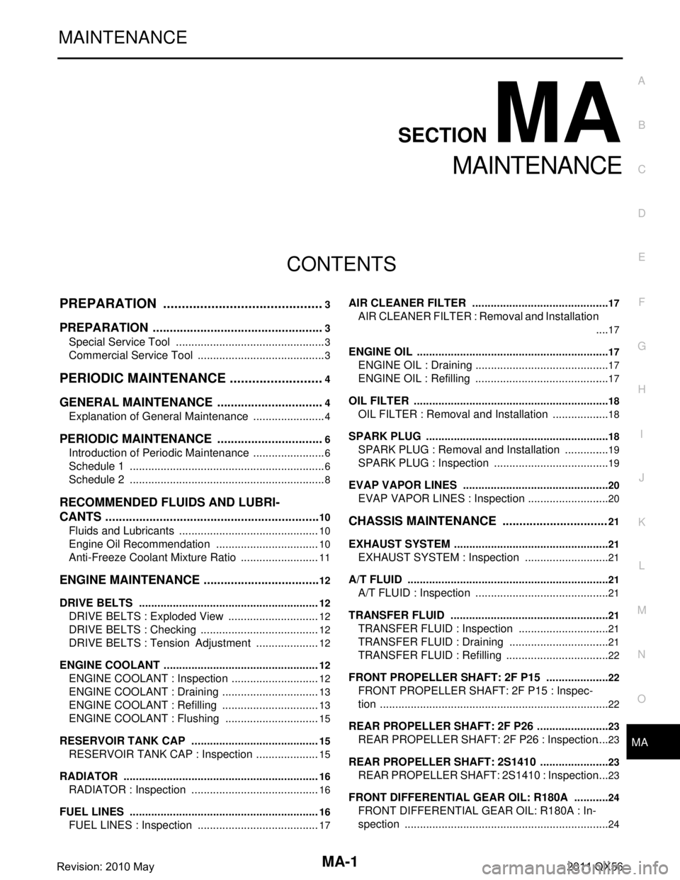
CONTENTS
MAINTENANCE
PREPARATION .............
...............................3
PREPARATION .............................................. .....3
Special Service Tool ........................................... ......3
Commercial Service Tool ..........................................3
PERIODIC MAINTENANCE ..........................4
GENERAL MAINTENANCE ........................... .....4
Explanation of General Maintenance .................. ......4
PERIODIC MAINTENANCE ................................6
Introduction of Periodic Maintenance .................. ......6
Schedule 1 ................................................................6
Schedule 2 ................................................................8
RECOMMENDED FLUIDS AND LUBRI-
CANTS ................................................................
10
Fluids and Lubricants .......................................... ....10
Engine Oil Recommendation ..................................10
Anti-Freeze Coolant Mixture Ratio ..........................11
ENGINE MAINTENANCE ...................................12
DRIVE BELTS ....................................................... ....12
DRIVE BELTS : Exploded View ..............................12
DRIVE BELTS : Checking .......................................12
DRIVE BELTS : Tension Adjustment .....................12
ENGINE COOLANT ............................................... ....12
ENGINE COOLANT : Inspection .............................12
ENGINE COOLANT : Draining ................................13
ENGINE COOLANT : Refilling ................................13
ENGINE COOLANT : Flushing ...............................15
RESERVOIR TANK CAP ..........................................15
RESERVOIR TANK CAP : Inspection ................. ....15
RADIATOR ............................................................ ....16
RADIATOR : Inspection ..........................................16
FUEL LINES .......................................................... ....16
FUEL LINES : Inspection ........................................17
AIR CLEANER FILTER ......................................... ....17
AIR CLEANER FILTER : Removal and Installation
....
17
ENGINE OIL ........................................................... ....17
ENGINE OIL : Draining ............................................17
ENGINE OIL : Refilling ............................................17
OIL FILTER ............................................................ ....18
OIL FILTER : Removal and Installation ...................18
SPARK PLUG ........................................................ ....18
SPARK PLUG : Removal and Installation ...............19
SPARK PLUG : Inspection ......................................19
EVAP VAPOR LINES ............................................ ....20
EVAP VAPOR LINES : Inspection ...........................20
CHASSIS MAINTENANCE ...............................21
EXHAUST SYSTEM . ..................................................21
EXHAUST SYSTEM : Inspec tion ............................21
A/T FLUID .............................................................. ....21
A/T FLUID : Inspection ............................................21
TRANSFER FLUID ................................................ ....21
TRANSFER FLUID : Inspection ..............................21
TRANSFER FLUID : Draining .................................21
TRANSFER FLUID : Refilling ..................................22
FRONT PROPELLER SHAFT: 2F P15 ................. ....22
FRONT PROPELLER SHAFT: 2F P15 : Inspec-
tion ...........................................................................
22
REAR PROPELLER SHAFT: 2F P26 .................... ....23
REAR PROPELLER SHAFT: 2F P26 : Inspection ....23
REAR PROPELLER SHAFT: 2S1410 ................... ....23
REAR PROPELLER SHAFT: 2S1410 : Inspection ....23
FRONT DIFFERENTIAL GEAR OIL: R180A ........ ....24
FRONT DIFFERENTIAL GEAR OIL: R180A : In-
spection ...................................................................
24
Revision: 2010 May2011 QX56
Page 5156 of 5598
![INFINITI QX56 2011 Factory Service Manual
TM-68
< ECU DIAGNOSIS INFORMATION >[7AT: RE7R01B]
TCM
ECU DIAGNOSIS INFORMATION
TCM
Reference ValueINFOID:0000000006226782
VALUES ON DIAGNOSIS TOOL
NOTE:
1. The CONSULT-III electrically displays shif INFINITI QX56 2011 Factory Service Manual
TM-68
< ECU DIAGNOSIS INFORMATION >[7AT: RE7R01B]
TCM
ECU DIAGNOSIS INFORMATION
TCM
Reference ValueINFOID:0000000006226782
VALUES ON DIAGNOSIS TOOL
NOTE:
1. The CONSULT-III electrically displays shif](/manual-img/42/57033/w960_57033-5155.png)
TM-68
< ECU DIAGNOSIS INFORMATION >[7AT: RE7R01B]
TCM
ECU DIAGNOSIS INFORMATION
TCM
Reference ValueINFOID:0000000006226782
VALUES ON DIAGNOSIS TOOL
NOTE:
1. The CONSULT-III electrically displays shift timi
ng and lock-up timing (that is, operation timing of each
solenoid).
Check for time difference between actual shift timi ng and the CONSULT-III display. If the difference is
noticeable, mechanical parts (except solenoids, sens ors, etc.) may be malfunctioning. Check mechanical
parts in accordance with the specified diagnostic procedures.
2. Shift schedule (that implies gear position) on CONSULT-III may slightly differ from that is described in Ser-
vice Manual. This occurs because of the reasons as per the following:
- Actual shift schedule has more or less tolerance or allowance
- Shift schedule in Service Manual refers to the point where shifting starts
- Gear position on CONSULT-III indicates the point where shifting completes
3. Display of solenoid valves on CONSULT-III changes at t he start of shifting, while gear position is displayed
upon completion of shifting (which is computed by TCM).
CONSULT-III MONITOR ITEM
Item name Condition Value / Status (Approx.)
VHCL/S SE-A/T During driving Approximately equals the speed-
ometer reading.
ESTM VSP SIG During driving Approximately equals the speed-
ometer reading.
OUTPUT REV During driving (lock-up ON) Tachometer / Gear ratio
INPUT SPEED During driving (lock-up ON) Approximately equals the engine
speed.
F SUN GR REV During driving Revolution of front sun gear is indi-
cated.
F CARR GR REV During driving Revolution of front carrier is indi-
cated.
ENGINE SPEED Eng ine running Closely equals the tachometer
reading.
TC SLIP SPEED During driving Engine speed − Input speed
ACCELE POSI Accelerator pedal is released 0.0/8
Accelerator pedal is fully depressed 8.0/8
THROTTLE POSI Accelerator pedal is released 0.0/8
Accelerator pedal is fully depressed 8.0/8
ATF TEMP 1 Ignition switch ON Temperature of ATF in the oil pan is
indicated.
ATF TEMP 2 Ignition switch ON Temperature of ATF at the exit of
torque converter.
AT F T E M P S E 1 0 °C (32 ° F) – 20 °C (68 °F) – 80 °C (176 °F) 3.3 – 2.7 – 0.9 V
BATTERY VOLT Ignition switch ON Battery voltage (11 V – 14 V)
LINE PRES SOL During driving 0.2 – 0.6 A
TCC SOLENOID Slip lock-up is active 0.2 – 0.8 A
Lock-up is active 0.8 A
Other than the above 0 A
L/B SOLENOID Low brake is engaged 0.6 – 0.8 A
Low brake is disengaged 0 – 0.05 A
Revision: 2010 May2011 QX56
Page 5404 of 5598

VTL-18
< SERVICE DATA AND SPECIFICATIONS (SDS)
SERVICE DATA AND SPECIFICATIONS (SDS)
SERVICE DATA AND SPECIFICATIONS (SDS)
SERVICE DATA AND SPECIFICATIONS (SDS)
In-cabin microfilterINFOID:0000000006276316
Replacement intervalMA-6, "Schedule 1" and MA-8, "Schedule 2"
Revision: 2010 May2011 QX56
Page 5513 of 5598

ROAD WHEELWT-63
< PERIODIC MAINTENANCE >
C
DF
G H
I
J
K L
M A
B
WT
N
O P
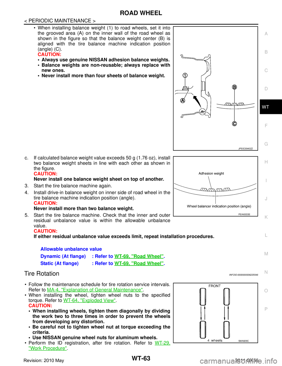
When installing balance weight (1) to road wheels, set it into the grooved area (A) on the inner wall of the road wheel as
shown in the figure so that the balance weight center (B) is
aligned with the tire balance machine indication position
(angle) (C).
CAUTION:
Always use genuine NISSAN ad hesion balance weights.
Balance weights are non-re usable; always replace with
new ones.
Never install more than four sheets of balance weight.
c. If calculated balance weight value exceeds 50 g (1.76 oz), install two balance weight sheets in line with each other as shown in
the figure.
CAUTION:
Never install one balance weight sheet on top of another.
3. Start the tire balance machine again.
4. Install drive-in balance weight on inner side of road wheel in the tire balance machine indication position (angle).
CAUTION:
Never install more than two balance weight.
5. Start the tire balance machine. Check that the inner and outer residual unbalance value is within the allowable unbalance
value.
CAUTION:
If either residual unbalan ce value exceeds limit, repeat installation procedures.
Tire RotationINFOID:0000000006225546
Follow the maintenance schedule for tire rotation service intervals.
Refer to MA-4, "
Explanation of General Maintenance".
When installing the wheel, tighten wheel nuts to the specified torque. Refer to WT-64, "
Exploded View".
CAUTION:
When installing wheels, tighte n them diagonally by dividing
the work two to three times in order to prevent the wheels
from developing any distortion.
Be careful not to tighten wh eel nut at torque exceeding the
criteria.
Use NISSAN genuine wheel nuts for aluminum wheels.
Perform the ID registration, after tire rotation. Refer to WT-29,
"Work Procedure".
JPEIC0040ZZ
Allowable unbalance value
Dynamic (At flange) : Refer to WT-69, "
Road Wheel".
Static (At flange) : Refer to WT-69, "
Road Wheel".
PEIA0033E
SMA829C
Revision: 2010 May2011 QX56