2011 INFINITI QX56 ground
[x] Cancel search: groundPage 3008 of 5598
GI-44
< BASIC INSPECTION >
SERVICE INFORMATION FOR ELECTRICAL INCIDENT
no voltage: open is between fuse block and SW1 (point A).
Close SW1 and probe at relay. voltage: open is further down the circuit than the relay.
no voltage: open is between SW1 and relay (point B).
Close the relay and probe at the solenoid. voltage: open is further down the circuit than the solenoid.
no voltage: open is between relay and solenoid (point C).
Any powered circuit can be diagnosed using the approach in the previous example.
TESTING FOR “SHORTS” IN THE CIRCUIT
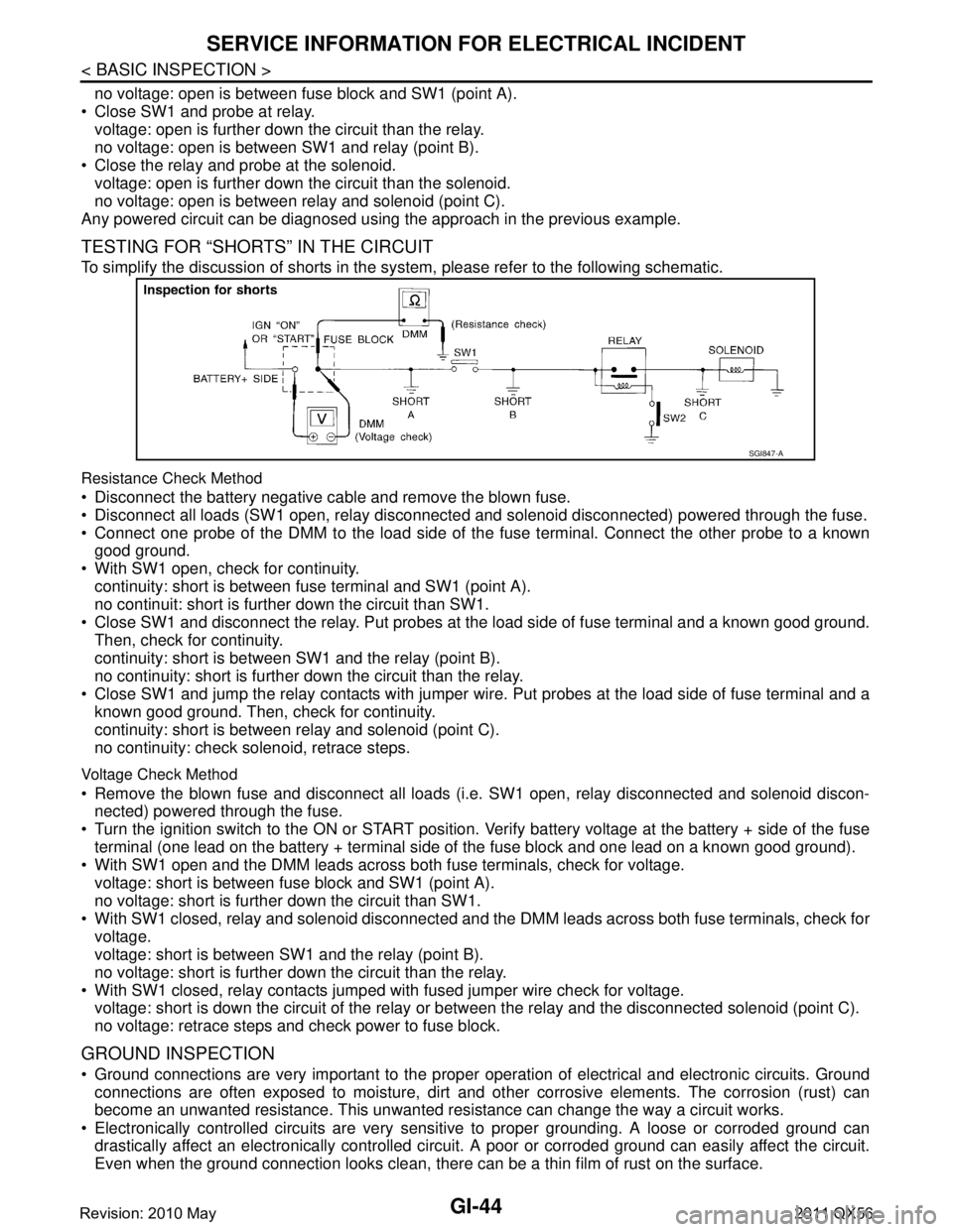
To simplify the discussion of shorts in the sy stem, please refer to the following schematic.
Resistance Check Method
Disconnect the battery negative cable and remove the blown fuse.
Disconnect all loads (SW1 open, relay disconnected and solenoid disconnected) powered through the fuse.
Connect one probe of the DMM to the load side of the fuse terminal. Connect the other probe to a known
good ground.
With SW1 open, check for continuity. continuity: short is between fuse terminal and SW1 (point A).
no continuit: short is further down the circuit than SW1.
Close SW1 and disconnect the relay. Put probes at the load side of fuse terminal and a known good ground. Then, check for continuity.
continuity: short is between SW1 and the relay (point B).
no continuity: short is further down the circuit than the relay.
Close SW1 and jump the relay contacts with jumper wir e. Put probes at the load side of fuse terminal and a
known good ground. Then, check for continuity.
continuity: short is between relay and solenoid (point C).
no continuity: check solenoid, retrace steps.
Voltage Check Method
Remove the blown fuse and disconnect all loads (i .e. SW1 open, relay disconnected and solenoid discon-
nected) powered through the fuse.
Turn the ignition switch to the ON or START position. Verify battery voltage at the battery + side of the fuse
terminal (one lead on the battery + terminal side of the fuse block and one lead on a known good ground).
With SW1 open and the DMM leads across both fuse terminals, check for voltage. voltage: short is between fuse block and SW1 (point A).
no voltage: short is further down the circuit than SW1.
With SW1 closed, relay and solenoid disconnected and the DMM leads across both fuse terminals, check for
voltage.
voltage: short is between SW1 and the relay (point B).
no voltage: short is further down the circuit than the relay.
With SW1 closed, relay contacts jumped with fused jumper wire check for voltage. voltage: short is down the circuit of the relay or between the relay and the disconnected solenoid (point C).
no voltage: retrace steps and check power to fuse block.
GROUND INSPECTION
Ground connections are very important to the proper operation of electrical and electronic circuits. Ground
connections are often exposed to moisture, dirt and other corrosive elements. The corrosion (rust) can
become an unwanted resistance. This unwanted resistance can change the way a circuit works.
Electronically controlled circuits are very sens itive to proper grounding. A loose or corroded ground can
drastically affect an electronically controlled circuit. A poor or corroded ground can easily affect the circuit.
Even when the ground connection looks clean, there c an be a thin film of rust on the surface.
SGI847-A
Revision: 2010 May2011 QX56
Page 3009 of 5598
SERVICE INFORMATION FOR ELECTRICAL INCIDENTGI-45
< BASIC INSPECTION >
C
DE
F
G H
I
J
K L
M B
GI
N
O P
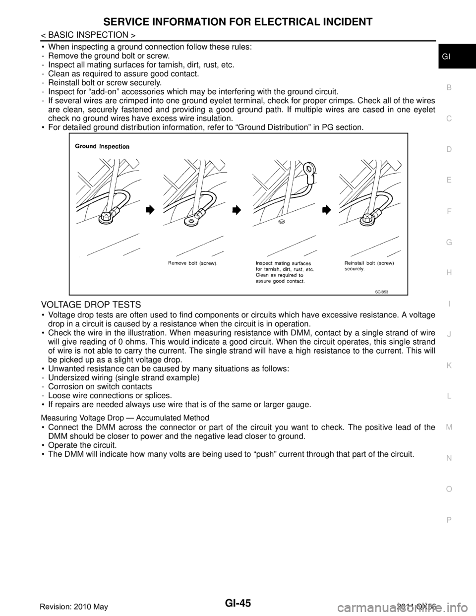
When inspecting a ground connection follow these rules:
- Remove the ground bolt or screw.
- Inspect all mating surfaces for tarnish, dirt, rust, etc.
- Clean as required to assure good contact.
- Reinstall bolt or screw securely.
- Inspect for “add-on” accessories which may be interfering with the ground circuit.
- If several wires are crimped into one ground eyelet terminal, check for proper crimps. Check all of the wires are clean, securely fastened and providing a good ground path. If multiple wires are cased in one eyelet
check no ground wires have excess wire insulation.
For detailed ground distribution information, re fer to “Ground Distribution” in PG section.
VOLTAGE DROP TESTS
Voltage drop tests are often used to find components or circuits which have excessive resistance. A voltage
drop in a circuit is caused by a resistance when the circuit is in operation.
Check the wire in the illustration. When measuring re sistance with DMM, contact by a single strand of wire
will give reading of 0 ohms. This would indicate a good circuit. When the circuit operates, this single strand
of wire is not able to carry the current. The single st rand will have a high resistance to the current. This will
be picked up as a slight voltage drop.
Unwanted resistance can be caused by many situations as follows:
- Undersized wiring (single strand example)
- Corrosion on switch contacts
- Loose wire connections or splices.
If repairs are needed always use wire that is of the same or larger gauge.
Measuring Voltage Drop — Accumulated Method
Connect the DMM across the connector or part of the ci rcuit you want to check. The positive lead of the
DMM should be closer to power and the negative lead closer to ground.
Operate the circuit.
The DMM will indicate how many volts are being used to “push” current through that part of the circuit.
SGI853
Revision: 2010 May2011 QX56
Page 3011 of 5598
SERVICE INFORMATION FOR ELECTRICAL INCIDENTGI-47
< BASIC INSPECTION >
C
DE
F
G H
I
J
K L
M B
GI
N
O P
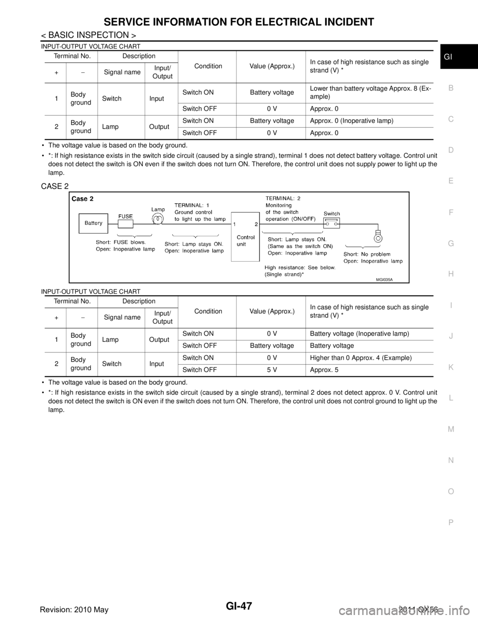
INPUT-OUTPUT VOLTAGE CHART
The voltage value is based on the body ground.
*: If high resistance exists in the switch side circuit (caused by a single strand), terminal 1 does not detect battery voltag e. Control unit
does not detect the switch is ON even if the switch does not turn ON. Therefore, the control unit does not supply power to ligh t up the
lamp.
CASE 2
INPUT-OUTPUT VOLTAGE CHART
The voltage value is based on the body ground.
*: If high resistance exists in the switch side circuit (caused by a single strand), terminal 2 does not detect approx. 0 V. C ontrol unit
does not detect the switch is ON even if the switch does not turn ON. Therefore, the control unit does not control ground to li ght up the
lamp. Terminal No. Description
Condition Value (Approx.)In case of high resistance such as single
strand (V) *
+ −Signal name Input/
Output
1 Body
ground Switch Input Switch ON Battery voltage
Lower than battery voltage Approx. 8 (Ex-
ample)
Switch OFF 0 V Approx. 0
2 Body
ground Lamp Output Switch ON Battery voltage App
rox. 0 (Inoperative lamp)
Switch OFF 0 V Approx. 0
Terminal No. Description Condition Value (Approx.)In case of high resistance such as single
strand (V) *
+ −Signal name Input/
Output
1 Body
ground Lamp Output Switch ON 0 V Battery voltage (Inoperative lamp)
Switch OFF Battery voltage Battery voltage
2 Body
ground Switch Input Switch ON 0 V Higher than 0 Approx. 4 (Example)
Switch OFF 5 V Approx. 5
MGI035A
Revision: 2010 May2011 QX56
Page 3014 of 5598

GI-50
< BASIC INSPECTION >
CONSULT-III/GST CHECKING SYSTEM
CONSULT-III/GST Data Link Connector (DLC) Circuit
INFOID:0000000006280858
INSPECTION PROCEDURE
If the CONSULT-III/GST cannot diagnose the system properly, check the following items.
NOTE:
The DDL1 and DDL2 circuits from DLC pins 12, 13, 14 and 15 may be connected to more than one system. A
short in a DDL circuit connected to a control unit in one system may affect CONSULT-III access to other sys-
tems.
If the GST cannot operate properly, check the circ uit based on the information of SAE J1962 and ISO 15031-
3.
Symptom Check item
CONSULT-III/GST cannot ac-
cess any system. CONSULT-III/GST DLC power supply circuit (Terminal 8 and 16) and ground circuit (Terminal 4 and
5)
CONSULT-III cannot access in-
dividual system. (Other sys-
tems can be accessed.) Power supply and ground circuit for the control unit of the system (For detailed circuit, refer to wiring
diagram for each system.)
Open or short circuit between the system and CONSULT-III DLC (For detailed circuit, refer to wiring
diagram for each system.)
Open or short circuit CAN communication line. Refer to LAN-18, "
Trouble Diagnosis Flow Chart".
Revision: 2010 May2011 QX56
Page 3045 of 5598
GW-16
< REMOVAL AND INSTALLATION >
BACK DOOR WINDOW GLASS
BACK DOOR WINDOW GLASS
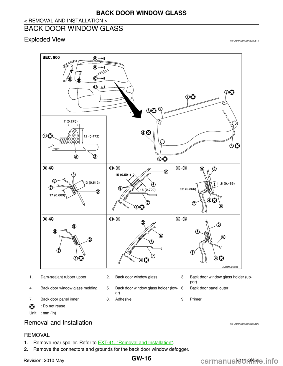
Exploded ViewINFOID:0000000006220819
Removal and InstallationINFOID:0000000006220820
REMOVAL
1. Remove rear spoiler. Refer to EXT-41, "Removal and Installation".
2. Remove the connectors and grounds for the back door window defogger.
1. Dam-sealant rubber upper 2. Back door window glass 3. Back door window glass holder (up- per)
4. Back door window glass molding 5. Back door window glass holder (low- er)6. Back door panel outer
7. Back door panel inner 8. Adhesive 9. Primer : Do not reuse
Unit : mm (in)
JMKIA5457GB
Revision: 2010 May2011 QX56
Page 3091 of 5598
COOLER PIPE AND HOSEHA-35
< REMOVAL AND INSTALLATION >
C
DE
F
G H
J
K L
M A
B
HA
N
O P
Check for leakages when recharging refrigerant. Refer to HA-18, "Leak Test".
LOW-PRESSURE FLEXIBLE HOSE
LOW-PRESSURE FLEXIBLE HOSE : Removal and InstallationINFOID:0000000006276174
CAUTION:
Perform lubricant return operation before each refrigeration system disassembly. However, if a large
amount of refrigerant or lubricant is detected, n ever perform lubricant return operation. Refer to HA-
22, "Perform Lubricant Return Operation".
REMOVAL
1. Use a refrigerant collecting equipment (for HF C-B4a) to discharge the refrigerant. Refer to HA-22, "Per-
form Lubricant Return Operation".
2. Remove air cleaner. Refer to EM-27, "
Removal and Installation".
3. Remove the mounting bolt installed in low-pressure flexible hose from the vehicle.
4. Remove mounting bolts, and then remove low-pressure flexible hose from the vehicle. CAUTION:
Cap or wrap the joint of the A/C piping and comp ressor with suitable material such as vinyl tape to
avoid the entry of air.
INSTALLATION
Note the following items, and install in the reverse order of removal.
CAUTION:
Replace O-rings with new ones. Then apply compressor oil to them when installing.
Check for leakages when recharging refrigerant. Refer to HA-18, "
Leak Test".
HIGH-PRESSURE PIPE
HIGH-PRESSURE PIPE : Removal and InstallationINFOID:0000000006276175
CAUTION:
Perform lubricant return operati on before each refrigeration system disassembly. However, if a large
amount of refrigerant or lubricant is detected, n ever perform lubricant return operation. Refer to HA-
22, "Perform Lubricant Return Operation".
REMOVAL
1. Use a refrigerant collecting equipment (for HF C-134a) to discharge the refrigerant. Refer to HA-22, "Per-
form Lubricant Return Operation".
2. Remove low-pressure pipe. Refer to HA-36, "
LOW-PRESSURE PIPE : Removal and Installation".
3. Remove battery. Refer to PG-164, "
Removal and Installation".
4. Remove mounting bolts, and then remove battery bracket.
5. Disconnect harness connector, harness clip and ground harness for securing work space.
6. Remove mounting bolt, and then disconnec t high-pressure pipe from condenser.
CAUTION:
Cap or wrap the joint of the A/C piping and comp ressor with suitable material such as vinyl tape to
avoid the entry of air.
7. Remove high-pressure pipe mounting nut.
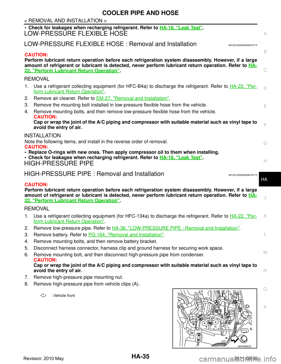
8. Remove high-pressure pipe from vehicle clips (A).
: Vehicle front
JMIIA0682ZZ
Revision: 2010 May2011 QX56
Page 3099 of 5598
A/C UNIT ASSEMBLYHA-43
< REMOVAL AND INSTALLATION >
C
DE
F
G H
J
K L
M A
B
HA
N
O P
Perform lubricant return operati on before each refrigeration system disassembly. However, if a large
amount of refrigerant or lubricant is detected, n ever perform lubricant return operation. Refer to HA-
22, "Perform Lubricant Return Operation".
REMOVAL
1. Use a refrigerant collecting equipment (for HF C-134a) to discharge the refrigerant. Refer to HA-20, "Recy-
cle Refrigerant". (If equipped)
2. Drain engine coolant from cooling system. Refer to CO-8, "
Draining".
3. Remove clamps, and then disconnect front heater outlet hose from heater pipe.
CAUTION:
Some coolant may spill when heater hoses are disconnected.
Close off the coolant inlet and outlet on the heater core (2 locations) with shop cloths.
4. Remove mounting bolt, and then disconnect low-pressure pipe and high-pressure pipe from expansion valve.
CAUTION:
Cap or wrap the joint of the A/C piping and expan sion valve with suitable material such as vinyl
tape to avoid the entry of air.
5. Remove instrument panel assembly. Refer to IP-14, "
Removal and Installation".
6. Remove steering column mounting bolt and nuts. Refer to ST-34, "
Removal and Installation".
7. Move steering column assembly to a position where it does not inhibit work.
8. Disconnect harness clips, harness connectors, ground bol ts and blackets from steering member, and then
move the vehicle harness to the position without hindrance for work.
9. Remove mounting nuts, and then remove instrument stay (RH and LH).
10. Remove A/C unit assembly mounting bolts.
11. Remove mounting bolts, and then remove steering member from the vehicle.
12. Disconnect drain hose from A/C unit assembly, and then remove A/C unit assembly from the vehicle.
13. Remove mounting bolts, and then disconnect heater & cooling unit and blower unitassembly.
INSTALLATION
Note the following items, and install in the reverse order of removal.
CAUTION:
Replace O-rings with new ones. Then apply compressor oil to them when installing.
Check for leakages when recharging refrigerant. Refer to HA-18, "
Leak Test".
NOTE:
Refer to CO-9, "
Refilling" when filling radiator with engine coolant.
EVAPORATOR
EVAPORATOR : Removal and InstallationINFOID:0000000006276184
REMOVAL
1. Remove heater & cooling unit assembly. Refer to HA-41, "Exploded View".
2. Remove heater core. Refer to HA-44, "
HEATER CORE : Removal and Installation".
3. Remove mounting screws, and then remove evaporator pipe cover.
4. Remove air mix door motor (RH). Refer to HAC-153, "
AIR MIX DOOR MOTOR : Removal and Installa-
tion".
5. Remove mounting screws, and then remove A/C cover.
6. Remove foot duct LH. Refer to VTL-11, "
FLOOR DUCT 1 : Removal and Installation".
7. Remove mounting screws, and then remove A/C lower case.
8. Remove intake sensor. Refer to HAC-150, "
Removal and Installation".
9. Remove evaporator assembly from heater & cooling unit assembly.
10. Remove mounting bolts, and then remove evaporator from evaporator assembly.
CAUTION:
Cap or wrap the joint of the evaporator and evaporat or pipe assembly with suitable material such as
vinyl tape to avoid the entry of air.
Revision: 2010 May2011 QX56
Page 3109 of 5598

HAC-3
C
DE
F
G H
J
K L
M A
B
HAC
N
O P
B2630, B2631 SUNLOAD SENSOR (DRIVER
SIDE) .............................................................. ....
86
DTC Logic ........................................................... ....86
Diagnosis Procedure ...............................................86
Component Inspection ............................................87
B2632, B2633 FRONT AIR MIX DOOR MO-
TOR (DRIVER SIDE) ..........................................
89
DTC Logic ........................................................... ....89
Diagnosis Procedure ...............................................89
B2634, B2635 FRONT AIR MIX DOOR MO-
TOR (PASSENGER SIDE) .................................
91
DTC Logic ........................................................... ....91
Diagnosis Procedure ...............................................91
B2636, B2637, B2638, B2639, B2654, B2655
FRONT MODE DOOR MOTOR ..........................
93
DTC Logic ........................................................... ....93
Diagnosis Procedure ...............................................93
B263D, B263E, B263F INTAKE DOOR MO-
TOR ....................................................................
95
DTC Logic ........................................................... ....95
Diagnosis Procedure ...............................................95
B2661, B2662, B2663 UPPER VENTILATOR
DOOR MOTOR ...................................................
97
DTC Logic ........................................................... ....97
Diagnosis Procedure ...............................................97
B2664, B2665 REAR AIR MIX DOOR MOTOR
....
99
DTC Logic ........................................................... ....99
Diagnosis Procedure ...............................................99
B2666, B2669, B266A REAR MODE DOOR
MOTOR .............................................................
101
DTC Logic ........................................................... ..101
Diagnosis Procedure .............................................101
B2667, B2668 SUNLOAD SENSOR (PAS-
SENGER SIDE) ................................................
103
DTC Logic ........................................................... ..103
Diagnosis Procedure .............................................103
Component Inspection ..........................................104
B266B, B266C REAR IN-VEHICLE SENSOR ..106
DTC Logic ........................................................... ..106
Diagnosis Procedure .............................................106
Component Inspection ..........................................107
B27B0 A/C AUTO AMP. ..................................109
DTC Logic ........................................................... ..109
Diagnosis Procedure .............................................109
POWER SUPPLY AND GROUND CIRCUIT ....110
A/C AUTO AMP. .................................................... ..110
A/C AUTO AMP. : Diagnosis Procedure ...............110
FRONT AIR MIX DOOR MOTOR (DRIVER SIDE) ..110
FRONT AIR MIX DOOR MOTOR (DRIVER SIDE)
: Diagnosis Procedure ......................................... ..
110
FRONT AIR MIX DOOR MOTOR (PASSENGER
SIDE) ...................................................................... ..
111
FRONT AIR MIX DOOR MOTOR (PASSENGER
SIDE) : Diagnosis Procedure .................................
111
FRONT MODE DOOR MOTOR ............................. ..112
FRONT MODE DOOR MOTOR : Diagnosis Pro-
cedure ....................................................................
112
INTAKE DOOR MOTOR ........................................ ..113
INTAKE DOOR MOTOR : Diagnosis Procedure ...113
REAR AIR MIX DOOR MOTOR ............................. ..114
REAR AIR MIX DOOR MOTOR : Diagnosis Pro-
cedure .................................................................. ..
114
REAR A/C CONTROL ........................................... ..115
REAR A/C CONTROL : Diagnosis Procedure .......115
REAR MODE DOOR MOTOR ............................... ..116
REAR MODE DOOR MOTOR : Diagnosis Proce-
dure .......................................................................
116
UPPER VENTILATOR DOOR MOTOR ...................116
UPPER VENTILATOR DOOR MOTOR : Diagno-
sis Procedure ....................................................... ..
116
DOOR MOTOR ................................................118
Diagnosis Procedure .............................................118
DOOR MOTOR COMMUNICATION CIRCUIT .120
Diagnosis Procedure .............................................120
FRONT BLOWER MOTOR .............................121
Diagnosis Procedure .............................................121
Component Inspection (Front Blower Motor) .........122
Component Inspection (Blower Relay) ..................123
IONIZER ..........................................................124
Component Function Check ..................................124
Diagnosis Procedure .............................................124
MAGNET CLUTCH .........................................126
Component Function Check ..................................126
Diagnosis Procedure .............................................126
REAR A/C CONTROL COMMUNICATION
SIGNAL ...........................................................
127
Diagnosis Procedure .............................................127
REAR A/C SOLENOID VALVE .......................128
Diagnosis Procedure .............................................128
Component Inspection ...........................................129
REAR BLOWER MOTOR ...............................131
Diagnosis Procedure .............................................131
Component Inspection ...........................................132
SYMPTOM DIAGNOSIS ............................133
Revision: 2010 May2011 QX56