2011 INFINITI QX56 condenser fan
[x] Cancel search: condenser fanPage 956 of 5598

CO-14
< REMOVAL AND INSTALLATION >
RADIATOR
to release built-up pressure. Carefully remove radiator cap by turning it all the way. Note that the reser-
voir tank cap side is also under pressure.
1. Remove front under cover with power tool. Refer to EXT-25, "
Exploded View".
2. Remove engine cover. Refer to EM-25, "
Exploded View".
3. Drain engine coolant from radiator. Refer to CO-8, "
Draining".
CAUTION:
Perform this step when the engine is cold.
Never spill engine coolant on drive belts.
4. Remove radiator hose (lower).
5. Remove fan shroud (lower). Refer to CO-13, "
Exploded View".
6. Move reservoir tank to the position without the hindrance for work.
7. Remove radiator core support cover. Refer to DLK-220, "
Exploded View".
8. Remove fan shroud (upper), refer to following.
a. Remove EVAP hose mounting bolts and move harness to aside.
b. Move air cleaner case to the position without the hindrance for work. Refer to EM-27, "
Exploded View".
NOTE:
The air cleaner case connector is not required to be disconnected.
9. Remove radiator grille. Refer to EXT-19, "
Exploded View".
10. Move condenser to the position without the hindranc e for work with the following procedures. Refer to HA-
38, "Exploded View".
Remove mounting bolts and disconnect A/C piping from radiator.
Remove air guide from radiator. Refer to EXT-12, "
Exploded View".
Remove radiator mounting bolts.
11. Remove radiator hose (upper).
12. Remove radiator as per the following: CAUTION:
Be careful not to damage radiator core.
Lift up and pull the radiator (1) forward, and then remove themounting rubber (lower) (3) from the radiator core support (2).
INSTALLATION
Note the following, and install in the reverse order of removal.
CAUTION:
Use genuine mounting bolts for th e cooling fan assembly and strictly observe the tightening torque.
(Breakage prevention for radiator)
NOTE:
Insert the radiator hose (1) all the way to the st opper (2) or by 33 mm (1.30 in) (hose without a stopper).
: Vehicle front
JPBIA3431ZZ
JPBIA4294GB
Revision: 2010 May2011 QX56
Page 1788 of 5598

DLK-252
< REMOVAL AND INSTALLATION >
CAB MOUNTING INSULATOR
Drain brake fluid from brake line. Refer to BR-10, "Draining".
Release fuel pressure. Refer to EC-153, "
Work Procedure".
Disconnect both battery cables. Refer to PG-164, "
Removal and Installation".
Drain engine coolant from radiator. Refer to CO-8, "
Draining".
Discharge refrigerant from A/C circuit. Refer to HA-20, "
Recycle Refrigerant".
Drain power steering fluid from reservoir tank.
4. Remove parts relating to connection of body assembly and frame assembly. Tire and wheel: Refer to WT-64, "
Removal and Installation" (with TPMS).
Front fender protector (LH and RH): Refer to EXT-23, "
FENDER PROTECTOR : Removal and Installa-
tion".
Front bumper: Refer to EXT-13, "
Removal and Installation".
Radiator core support upper: Refer to DLK-220, "
Removal and Installation".
Fan shroud: Refer to CO-16, "
Removal and Installation".
Battery and battery case: Refer to PG-164, "
Removal and Installation".
Air cleaner case (upper and lower): Refer to EM-27, "
Removal and Installation".
Engine cover: Refer to EM-25, "
Removal and Installation".
Rear wheel house protector (LH and RH): EXT-24, "
REAR WHEEL HOUSE PROTECTOR : Removal
and Installation".
Rear bumper: Refer to EXT-17, "
Removal and Installation".
Fuel filler tube: Remove to FL-8, "
Exploded View".
Spare tire
Towing hook bracket.
5. Separate parts relating to connection of body assembly and frame assembly. Vehicle front
Disconnect ICC sensor connector. (models with ICC) Refer to CCS-176, "
Removal and Installation".
Remove radiator upper hose and radiator lower hose from radiator assembly. Refer to CO-13,
"Exploded View".
Remove A/T fluid cooler hose B and A/T fluid cooler hose E from A/T fluid cooler tubes. Refer to TM-
202, "Exploded View".
Remove power steering return hose from oil cooler, and then power steering return hose clamp bolt from frame assembly. Refer to ST-54, "
Exploded View".
Remove power steering suction hose from reservoir tank. Refer to ST-54, "
Exploded View".
CAUTION:
Never spill power steering fluid in engine room.
Remove A/C low-presser flexible hose from A/C low-presser pipe. Refer to HA-35, "
LOW-PRESSURE
FLEXIBLE HOSE : Removal and Installation".
Remove A/C hi-presser flexible hose from condenser. Refer to HA-34, "
HIGH-PRESSURE FLEXIBLE
HOSE : Removal and Installation".
Remove all engine Control Harness connectors, har ness clips and others that are connected to the
body assembly side of the engine room. (engine room LH and RH side). Refer to PG-148, "
Engine Con-
trol Harness".
NOTE:
Separate harness connectors from ECM (engine control module). Refer to EC-10, "
General Precau-
tions".
CAUTION:
When pulling out harnesses, never damage harnesses or connectors.
After temporarily securing connectors, cover th em with vinyl or similar material to protect
against adhesion of foreign materials.
Disconnect engine room harness connectors and remo ve harness clips from engine assembly (engine
RH side). Refer to PG-146, "
Engine Room Harness".
Remove heater hoses from front water outlet tube (engine room RH side). Refer to HA-33, "
Exploded
View".
Disconnect front wheel sensor connectors (LH and RH). Refer to BRC-134, "
FRONT WHEEL SENSOR
: Exploded View".
Disconnect fuel feed tube and EVAP hos e (front wheel well LH side).
Remove steering lower shaft from steering gear side assembly. Refer to ST-37, "
Removal and Installa-
tion"
CAUTION:
Spiral cable may be cut if steering wheel turns while separating steering column assembly and
steering gear assembly.
Revision: 2010 May2011 QX56
Page 2032 of 5598

EC-8
P2A00, P2A03 A/F SENSOR 1 .......................487
DTC Logic ............................................................ ..487
Diagnosis Procedure .............................................487
ASCD BRAKE SWITCH ................................. .490
Component Function Check ................................ ..490
Diagnosis Procedure .............................................490
Component Inspection (ASCD Brake Switch) .......491
ASCD INDICATOR ..........................................492
Component Function Check ................................ ..492
Diagnosis Procedure .............................................492
ELECTRICAL LOAD SIGNAL .........................493
Description ........................................................... ..493
Component Function Check ..................................493
Diagnosis Procedure .............................................493
ELECTRICALLY-CONTROLLED COOLING
FAN COUPLING ..............................................
495
Component Function Check ................................ ..495
Diagnosis Procedure .............................................495
FUEL INJECTOR .............................................498
Component Function Check ................................ ..498
Diagnosis Procedure .............................................498
Component Inspection ...........................................499
HIGH PRESSURE FUEL PUMP ......................501
Component Function Check ................................ ..501
Diagnosis Procedure .............................................501
Component Inspection ...........................................502
ICC BRAKE SWITCH ......................................503
Component Function Check ................................ ..503
Diagnosis Procedure .............................................503
Component Inspection (ICC Brake Switch) ...........505
IGNITION SIGNAL ...........................................506
Component Function Check ................................ ..506
Diagnosis Procedure .............................................506
Component Inspection (Ignition Coil with Power
Transistor) .............................................................
509
Component Inspection (Condenser) ......................510
INFORMATION DISPLAY (ASCD) ..................511
Component Function Check ................................ ..511
Diagnosis Procedure .............................................511
LOW PRESSURE FUEL PUMP ......................512
Component Function Check ................................ ..512
Diagnosis Procedure .............................................512
Component Inspection (Low Pressure Fuel Pump)
..
513
Component Inspection (FPCM) .............................514
MALFUNCTION INDICATOR LAMP ...............515
Component Function Check ................................ ..515
Diagnosis Procedure .............................................515
ON BOARD REFUELING VAPOR RECOV-
ERY (ORVR) .....................................................
516
Component Function Check ................................ .516
Diagnosis Procedure .............................................516
Component Inspection (EVAP Vapor Cut Valve) . .518
REFRIGERANT PRESSURE SENSOR ......... ..520
Component Function Check ................................ .520
Diagnosis Procedure .............................................520
SNOW MODE SWITCH ....................................522
Description ........................................................... .522
Component Function Check .................................522
Diagnosis Procedure .............................................522
Component Inspection ..........................................523
SYMPTOM DIAGNOSIS ...........................524
ENGINE CONTROL SYSTEM SYMPTOMS .. ..524
Symptom Table .................................................... .524
NORMAL OPERATING CONDITION ...............529
Description ........................................................... .529
PERIODIC MAINTENANCE ......................530
IDLE SPEED .......................... ...........................530
Inspection ............................................................. .530
IGNITION TIMING .............................................531
Inspection ............................................................. .531
EVAP LEAK CHECK ........................................532
Inspection ............................................................. .532
POSITIVE CRANKCASE VENTILATION .........534
Inspection ............................................................. .534
REMOVAL AND INSTALLATION .............535
ECM ................................................................ ..535
Removal and Installation ...................................... .535
VVEL CONTROL MODULE .............................536
Removal and Installation ...................................... .536
FUEL PUMP CONTROL MODULE (FPCM) ....537
Removal and Installation ...................................... .537
SERVICE DATA AND SPECIFICATIONS
(SDS) ........ .................................................
538
SERVICE DATA AND SPECIFICATIONS
(SDS) .............................................................. ..
538
Idle Speed ............................................................ .538
Ignition Timing .......................................................538
Calculated Load Value ..........................................538
Mass Air Flow Sensor ...........................................538
Revision: 2010 May2011 QX56
Page 3075 of 5598

REFRIGERANTHA-19
< BASIC INSPECTION >
C
DE
F
G H
J
K L
M A
B
HA
N
O P
Never look directly into UV lamp light source.
NOTE:
For continuous operating time of UV lamp, fo llow the manufacturer operating instructions.
Illuminate piping joints from different angles us ing UV lamp and check that there is no leakage.
Use a mirror in area that is difficult to see to check refrigerant leakage.
Refrigerant leakage from evaporator can be detected by soaking cotton swab or a similar material with
drain hose water and illuminating it using UV lamp.
Dust, dirt, and packing materials adhesive used for condenser, evaporator, and other locations may flu- oresce. Be careful not to misidentify leakage.
5. Repair or replace parts where refrigerant leak age occurs and wipe off fluorescent leak detection dye.
NOTE:
Completely wipe off fluorescent leak detection dy e from gaps between parts, screw threads, and others
using a cotton swab or similar materials.
6. Use a UV lamp to check that no fluorescent leak detection dye remains after finishing work. WARNING:
Never look directly into UV lamp light source.
NOTE:
For continuous operating time of UV lamp, fo llow the manufacturer operating instructions.
Dust, dirt, and packing materials adhesive used for condenser, evaporator, and other locations may flu-
oresce. Be careful not to misidentify leakage.
CHECK REFRIGERANT LEAKAGE USIN G ELECTRICAL LEAK DETECTOR
WARNING:
Never check refrigerant leakage while the engine is running.
CAUTION:
Be careful of the following items so that in accurate checks or misidentifications are avoided.
Never allow refrigerant vapor, shop chemical vapors, cigarette smoke, or others around the vehicle.
Always check refrigerant leakage in a low air flow environment so that refrigerant may not disperse
when leakage occurs.
1. Stop the engine.
2. Connect recovery/recycling/recharging equipment or manifold gauge set to A/C service valve.
3. Check that A/C refrigerant pressure is 345 kPa (3.52 kg/cm
2, 50 psi) or more when temperature is 16 °C
(61 °F) or more. When pressure is lower than the spec ified value, recycle refrigerant completely and fill
refrigerant to the specified level.
NOTE:
Leakages may not be detected if A/C refri gerant pressure is 345 kPa (3.52 kg/cm
2, 50 psi) or less when
temperature is less than 16 °C (61 °F).
4. Clean area where refrigerant leakage check is per formed, and check refrigerant leakage along all sur-
faces of pipe connections and A/C system com ponents using electrical leak detector probe.
CAUTION:
Continue checking when a leakage is found. Always continue and complete checking along all
pipe connections and A/C system co mponents for additional leakage.
When a leakage is detected, clean leakage area using compressed air and check again.
When checking leakage of cooling unit inside, al ways clean inside of drain hose so that the
probe surface may not be exposed to water or dirt.
NOTE:
Always check leakage starting from high-pressure side and continue to low-pressure side.
When checking leakage of cooling unit inside, operate blower fan motor for 15 minutes or more at the maximum fan speed while the engine is stopped, and then insert electrical leak detector probe into drain
hose and hold for 10 minutes or more.
When disconnecting shut-off valve that is connected to A/C service valve, always evacuate remaining
refrigerant so that misidentification can be avoided.
5. Repair or replace parts where refrigerant leak age is detected. (Leakage is detected but leakage area is
unknown. GO TO 6.)
6. Start the engine and set A/C control in the following conditions. A/C switch ON
Air flow: VENT (ventilation)
Intake door position: Recirculation
Revision: 2010 May2011 QX56
Page 3083 of 5598

REFRIGERATION SYSTEM SYMPTOMSHA-27
< SYMPTOM DIAGNOSIS >
C
DE
F
G H
J
K L
M A
B
HA
N
O P
SYMPTOM DIAGNOSIS
REFRIGERATION SYSTEM SYMPTOMS
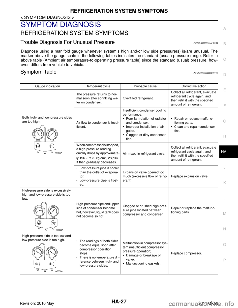
Trouble Diagnosis For Unusual PressureINFOID:0000000006276159
Diagnose using a manifold gauge whenever system’s high and/or low side pressure(s) is/are unusual. The
marker above the gauge scale in the following tables i ndicates the standard (usual) pressure range. Refer to
above table (Ambient air temperature-to-operating pre ssure table) since the standard (usual) pressure, how-
ever, differs from vehicle to vehicle.
Symptom TableINFOID:0000000006276160
Gauge indication Refrigerant cycle Probable cause Corrective action
Both high- and low-pressure sides
are too high. The pressure returns to nor-
mal soon after sprinkling wa-
ter on condenser.
Overfilled refrigerant. Collect all refrigerant, evacuate
refrigerant cycle again, and
then refill it with the specified
amount of refrigerant.
Air flow to condenser is insuf-
ficient. Insufficient condenser cooling
performance.
Poor fan rotation of radiator
and condenser.
Improper installation of air guide.
Clogged or dirty condenser fins. Repair or replace malfunc-
tioning parts.
Clean and repair condenser fins.
When compressor is stopped,
a high-pressure reading
quickly drops by approximate-
ly 196 kPa (2 kg/cm
2, 28 psi).
It then gradually decreases. Air mixed in refrigerant cycle.
Collect all refrigerant, evacuate
refrigerant cycle again, and
then refill it with the specified
amount of refrigerant.
Low-pressure pipe is cooler than the outlet of evapora-
tor.
Low-pressure pipe is frost- ed. Expansion valve opened too
much (excessive flow of refrig-
erant).
Replace expansion valve.
High-pressure side is excessively
high and low-pressure side is too
low. High-pressure pipe and upper
side of condenser become
hot, however, liquid tank does
not become so hot.Clogged or crushed high-pres-
sure pipe located between
compressor and condenser.
Repair or replace the malfunc-
tioning parts.
High-pressure side is too low and
low-pressure side is too high. The readings of both sides
become equal soon after
compressor operation
stops.
There is no temperature dif- ference between high- and
low-pressure sides. Malfunction in compressor sys-
tem (insufficient compressor
pressure operation).
Damage or breakage of
valve.
Malfunctioning gaskets. Replace compressor.
AC359A
AC360A
AC356A
Revision: 2010 May2011 QX56