2010 JAGUAR XFR list
[x] Cancel search: listPage 2084 of 3039
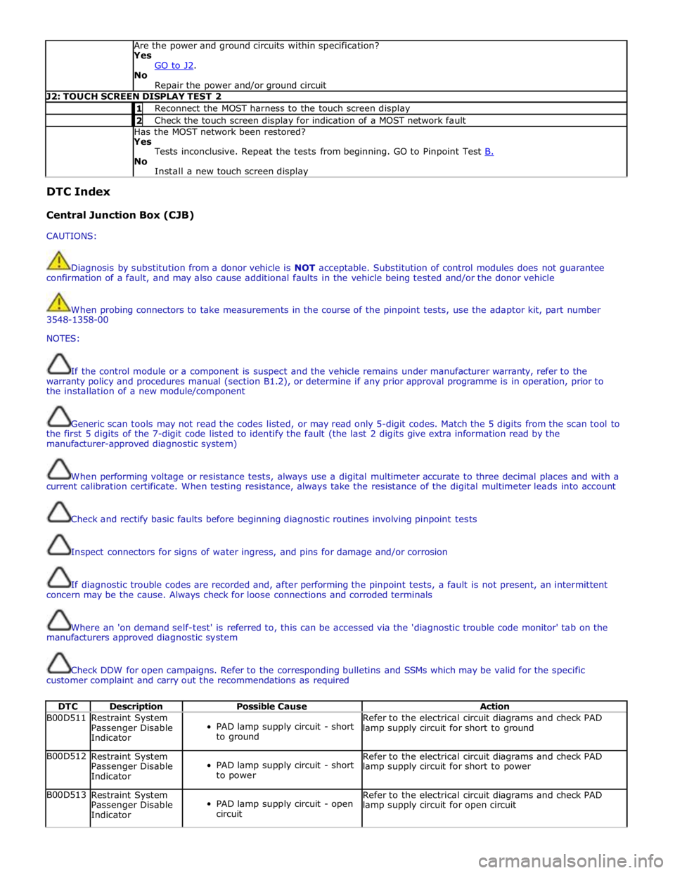
Are the power and ground circuits within specification?
Yes
GO to J2. No
Repair the power and/or ground circuit J2: TOUCH SCREEN DISPLAY TEST 2 1 Reconnect the MOST harness to the touch screen display 2 Check the touch screen display for indication of a MOST network fault Has the MOST network been restored?
Yes
Tests inconclusive. Repeat the tests from beginning. GO to Pinpoint Test B. No
Install a new touch screen display DTC Index
Central Junction Box (CJB)
CAUTIONS:
Diagnosis by substitution from a donor vehicle is NOT acceptable. Substitution of control modules does not guarantee
confirmation of a fault, and may also cause additional faults in the vehicle being tested and/or the donor vehicle
When probing connectors to take measurements in the course of the pinpoint tests, use the adaptor kit, part number
3548-1358-00
NOTES:
If the control module or a component is suspect and the vehicle remains under manufacturer warranty, refer to the
warranty policy and procedures manual (section B1.2), or determine if any prior approval programme is in operation, prior to
the installation of a new module/component
Generic scan tools may not read the codes listed, or may read only 5-digit codes. Match the 5 digits from the scan tool to
the first 5 digits of the 7-digit code listed to identify the fault (the last 2 digits give extra information read by the
manufacturer-approved diagnostic system)
When performing voltage or resistance tests, always use a digital multimeter accurate to three decimal places and with a
current calibration certificate. When testing resistance, always take the resistance of the digital multimeter leads into account
Check and rectify basic faults before beginning diagnostic routines involving pinpoint tests
Inspect connectors for signs of water ingress, and pins for damage and/or corrosion
If diagnostic trouble codes are recorded and, after performing the pinpoint tests, a fault is not present, an intermittent
concern may be the cause. Always check for loose connections and corroded terminals
Where an 'on demand self-test' is referred to, this can be accessed via the 'diagnostic trouble code monitor' tab on the
manufacturers approved diagnostic system
Check DDW for open campaigns. Refer to the corresponding bulletins and SSMs which may be valid for the specific
customer complaint and carry out the recommendations as required
DTC Description Possible Cause Action B00D511
Restraint System
Passenger Disable
Indicator
PAD lamp supply circuit - short
to ground Refer to the electrical circuit diagrams and check PAD
lamp supply circuit for short to ground B00D512
Restraint System
Passenger Disable
Indicator
PAD lamp supply circuit - short
to power Refer to the electrical circuit diagrams and check PAD
lamp supply circuit for short to power B00D513
Restraint System
Passenger Disable
Indicator
PAD lamp supply circuit - open
circuit Refer to the electrical circuit diagrams and check PAD
lamp supply circuit for open circuit
Page 2093 of 3039
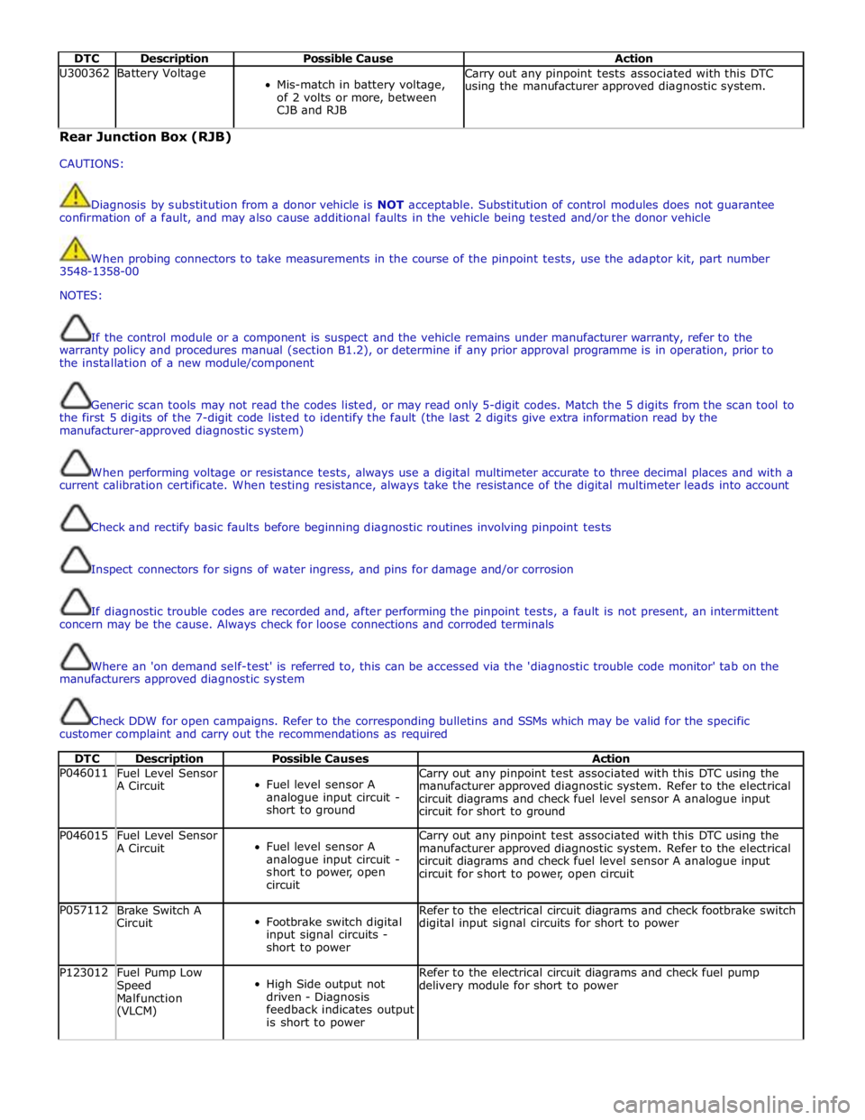
DTC Description Possible Cause Action U300362 Battery Voltage
Mis-match in battery voltage,
of 2 volts or more, between
CJB and RJB Carry out any pinpoint tests associated with this DTC
using the manufacturer approved diagnostic system. Rear Junction Box (RJB)
CAUTIONS:
Diagnosis by substitution from a donor vehicle is NOT acceptable. Substitution of control modules does not guarantee
confirmation of a fault, and may also cause additional faults in the vehicle being tested and/or the donor vehicle
When probing connectors to take measurements in the course of the pinpoint tests, use the adaptor kit, part number
3548-1358-00
NOTES:
If the control module or a component is suspect and the vehicle remains under manufacturer warranty, refer to the
warranty policy and procedures manual (section B1.2), or determine if any prior approval programme is in operation, prior to
the installation of a new module/component
Generic scan tools may not read the codes listed, or may read only 5-digit codes. Match the 5 digits from the scan tool to
the first 5 digits of the 7-digit code listed to identify the fault (the last 2 digits give extra information read by the
manufacturer-approved diagnostic system)
When performing voltage or resistance tests, always use a digital multimeter accurate to three decimal places and with a
current calibration certificate. When testing resistance, always take the resistance of the digital multimeter leads into account
Check and rectify basic faults before beginning diagnostic routines involving pinpoint tests
Inspect connectors for signs of water ingress, and pins for damage and/or corrosion
If diagnostic trouble codes are recorded and, after performing the pinpoint tests, a fault is not present, an intermittent
concern may be the cause. Always check for loose connections and corroded terminals
Where an 'on demand self-test' is referred to, this can be accessed via the 'diagnostic trouble code monitor' tab on the
manufacturers approved diagnostic system
Check DDW for open campaigns. Refer to the corresponding bulletins and SSMs which may be valid for the specific
customer complaint and carry out the recommendations as required
DTC Description Possible Causes Action P046011
Fuel Level Sensor
A Circuit
Fuel level sensor A
analogue input circuit -
short to ground Carry out any pinpoint test associated with this DTC using the
manufacturer approved diagnostic system. Refer to the electrical
circuit diagrams and check fuel level sensor A analogue input
circuit for short to ground P046015
Fuel Level Sensor
A Circuit
Fuel level sensor A
analogue input circuit -
short to power, open
circuit Carry out any pinpoint test associated with this DTC using the
manufacturer approved diagnostic system. Refer to the electrical
circuit diagrams and check fuel level sensor A analogue input
circuit for short to power, open circuit P057112
Brake Switch A
Circuit
Footbrake switch digital
input signal circuits -
short to power Refer to the electrical circuit diagrams and check footbrake switch
digital input signal circuits for short to power P123012
Fuel Pump Low
Speed
Malfunction
(VLCM)
High Side output not
driven - Diagnosis
feedback indicates output
is short to power Refer to the electrical circuit diagrams and check fuel pump
delivery module for short to power
Page 2106 of 3039

essential for prevention of moisture ingress that a sealed pre-terminated wiring harness must be used where a sealed terminal
was removed.
CAUTION: Where the repair procedure indicates that a glue lined heat shrink sleeve should be applied, apply sufficient
heat to the glue lined heat shrink to melt the glue in order to provide a water tight seal. Do not over heat the glue lined heat
shrink sleeve so that the wiring harness insulation becomes damaged.
Two sizes of heat shrink sleeving are available. Each heat shrink sleeve contains a sealant glue. These must be used when
connecting wiring harness(s) or electrical connector terminal(s) at all times. The smaller diameter heat shrink sleeve is to be
used with the red and blue butt splice connectors and the larger diameter sleeve with the yellow butt splice connectors.
For ease and speed, some of the pre-terminated wiring harness(s) may already have the insulation partly stripped at the splice
end. If the repair requires insulation to be stripped from the cable, refer to the Relationship Table for the correct length of
insulation to be stripped.
The Pre-Terminated Wiring Harness(s) illustration shows the electrical connector terminal type, the part number of the
pre-terminated wiring harness and the letter of the extractor tip which must be used to extract the electrical connector
terminal from the connector housing. Additionally, those electrical connector terminal(s) which are gold are identified, all
others are therefore, tinned and not gold.
Wiring Harness Cable Identification Sleeves
A selection of colored sleeves are available for maintaining the wiring harness cable identification on the pre-terminated wiring
harness. Place the correct colored sleeve(s) over the pre-terminated wiring harness insulation as near to the electrical
connector as possible with the main wiring harness cable color nearest to the electrical connector.
For example, if the original wiring harness cable color is pink with a black trace put the pink wiring harness cable identification
sleeve on the pre-terminated wiring harness first followed by a black sleeve, and slide both along the wiring harness cable to
the electrical connector terminal.
List of Parts
Description Part Number Quantity Pre-Terminated Wiring Harness(s) 418-066 to 418-103
inclusive 10 each Glue Lined Heat Shrink Pack – small diameter 418-104 25 per pack Glue Lined Heat Shrink Pack – larger diameter 418-105 10 per pack Case Assembly Comprising – carry case, lid, inner lid, base, insert, trays foam spacers 418-106 1 Butt Splice Connector – Red 418-107 50 per pack Butt Splice Connector – Blue 418-108 50 per pack Butt Splice Connector – Yellow 418-109 20 per pack Sleeve Identification Pack – for Red insulation 418-112 500 Sleeve Identification Pack – for Blue insulation 418-113 500 Sleeve Identification Pack – for Yellow insulation 418-114 500 Harness repair components can be ordered from Jaguar/Land Rover authorised parts.
Repair Tools
The wiring harness repair tools comprises:
Crimping pliers
A wire cutter and insulation stripper
An electrical connector terminal extraction handle and tips
Extraction Handle and Tips
The extraction handle, in conjunction with the correct tip, is used to remove a terminal from an electrical connector. Each tip is
marked with an identification letter, A to K inclusive. Each tip has been specially designed to extract a particular type of
electrical connector terminal. The use of any other tool is not recommended and is liable to cause damage to the electrical
connector. The tip is fastened to the handle by a screw which holds the tip firmly yet allows it to be easily replaced.
Page 2126 of 3039
Anti-Theft - Active - Anti-Theft - Active
Diagnosis and Testing
Principles of Operation Published: 26-Feb-2014
For a detailed description of the anti-theft - active system, refer to the relevant Description and Operation sections in the
workshop manual. REFER to: (419-01A Anti-Theft - Active)
Anti-Theft - Active (Description and Operation), Anti-Theft - Active (Description and Operation), Anti-Theft - Active (Description and Operation).
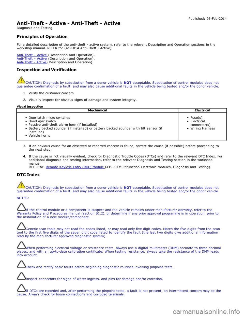
Inspection and Verification
CAUTION: Diagnosis by substitution from a donor vehicle is NOT acceptable. Substitution of control modules does not
guarantee confirmation of a fault, and may also cause additional faults in the vehicle being tested and/or the donor vehicle.
1. Verify the customer concern.
2. Visually inspect for obvious signs of damage and system integrity.
Visual Inspection
Mechanical Electrical
Door latch micro switches
Hood ajar switch
Passive anti-theft alarm horn (if installed)
Battery backed sounder (if installed) or battery backed sounder with tilt sensor (if
installed)
Vehicle horns
Fuse(s)
Electrical
connector(s)
Wiring Harness
3. If an obvious cause for an observed or reported concern is found, correct the cause (if possible) before proceeding to
the next step.
4. If the cause is not visually evident, check for Diagnostic Trouble Codes (DTCs) and refer to the relevant DTC Index. For
additional diagnosis and testing information, refer to the relevant Diagnosis and Testing section in the workshop
manual
REFER to: Remote Keyless Entry (RKE) Module (419-10 Multifunction Electronic Modules, Diagnosis and Testing).
DTC Index
CAUTION: Diagnosis by substitution from a donor vehicle is NOT acceptable. Substitution of control modules does not
guarantee confirmation of a fault, and may also cause additional faults in the vehicle being tested and/or the donor vehicle
NOTES:
If the control module or a component is suspect and the vehicle remains under manufacturer warranty, refer to the
Warranty Policy and Procedures manual (section B1.2), or determine if any prior approval programme is in operation, prior to
the installation of a new module/component.
Generic scan tools may not read the codes listed, or may read only five digit codes. Match the five digits from the scan
tool to the first five digits of the seven digit code listed to identify the fault (the last two digits give additional information
read by the manufacturer approved diagnostic system).
When performing electrical voltage or resistance tests, always use a digital multimeter (DMM) accurate to three decimal
places, and with an up-to-date calibration certificate. When testing resistance, always take the resistance of the DMM leads
into account.
Check and rectify basic faults before beginning diagnostic routines involving pinpoint tests.
Inspect connectors for signs of water ingress, and pins for damage and/or corrosion.
If DTCs are recorded and, after performing the pinpoint tests, a fault is not present, an intermittent concern may be the
cause. Always check for loose connections and corroded terminals.
Page 2146 of 3039

Check the Starter Relay circuit.
NOTE: On petrol engine variants, due to Smart Start, both sides of Relay Coil are switched directly from ECM (If
conditions correct). On diesel engine variants the low side only is switched directly from the ECM.
Check that the Steering Column Lock correctly operates and the steering wheel can turn freely.
Check that the High Speed CAN network is not malfunctioning, i.e. the CAN circuit is open or short circuit. This would mean
that the instrument cluster and ECM would be unable to communicate resulting in no Challenge being performed to enable the
ECM. This would be supported by LED Flash Code 24, see PATS Fault Code Table.
Also check the CAN network between the ABS module and the CJB. The CJB uses the CAN_BrakePressureTMC signal to
determine if the brake pedal has been pressed in order to allow an engine crank. The CJB uses a value of 0x05, if the CJB sees
a value less than this, it will not enable the Crank Request Output.
Engine cranks but will not start
If the Engine is cranking it means that the ECM has passed the authorisation required with the Instrument Cluster. If this
authorisation failed, the ECM would not engage the starter relay. This could be confirmed by verifying the PATS LED prove out
(illuminated solid for 3 seconds) or by reading DTCs from the instrument cluster and ECM.
In this case, the fuel pump circuit should be verified. The Fuel Pump Delivery Module (FPDM), which is supplied via the RJB
(authentication required with the instrument cluster) and controlled by the ECM, supplies the fuel pump.
In all cases of suspected non-start issues, the most logical failure modes should be eliminated first. i.e.
1. Check all relevant supplies and grounds to the relevant modules listed herein.
2. Note any unusual behaviour from other systems/functionality.
3. Note any functions that are not operating as expected.
PATS Fault Codes
For the various PATS modes/faults listed in the table , the instrument cluster will store a DTC and indicate this to the customer
during the detection period defined in the 'when logged' column, by illuminating the indicator as described for 60 seconds and
then flashing the LED 10 times as appropriate. The indication will stop immediately the ignition status is set to OFF any time
during the fault indication sequence. Up to 4 DTCs could be stored per key read sequence (1-10 read attempts). No DTCs will be
stored until all retry attempts are complete. Only the highest priority fault code will be flashed.
To determine the fault code from the LED: The LED will flash initially ten times with 1.5 seconds between. The LED will remain
OFF for 2.5 seconds then flash a number of times with 0.5 seconds between (the number of times the LED flashes represents
the first digit of the code), the LED will remain OFF for 1.5 seconds then flash a number of times with 1.5 seconds between
(the number of times the LED flashes represents the second digit of the code).
The PATS LED will be commanded on as shown under 'indication'. Normal PATS operations are complete within 400ms of the
ignition switch transition from OFF to ON or START, worst case for ECM communication problems will be less than 2 seconds. If
PATS is not complete during the 2 seconds the ECM will terminate PATS and await the next ignition ON or START event. PATS
faults will be indicated via the LED as soon as possible and will terminate the LED prove out. At ignition OFF all previous
flashing will cease and the perimeter anti-theft system will control the LED when the vehicle is locked and armed.
PATS Fault Code Table
Mode of Operation/Fault
When Logged
Ignition
Status
DTC LED
Fault
Code
Indication Prove out N/A Transition
from OFF to
ON N/A N/A
3 Seconds of steady
illumination Perimeter Anti-theft Control N/A OFF -
Vehicle
locked and
armed N/A N/A
Off or 0.5Hz flashing
at 5% duty cycle ±
20% until Off Start Control Unit already programmed Key Insert Any B1B0105 N/A No Indication Start Control Unit status = invalid response Key Insert Any B1B0167 N/A No Indication Start Control Unit programming error Key Insert Any B1B0151 N/A No Indication Start Control Unit challenge response error Key Insert OFF B1B0162 N/A No Indication Key Programming timer expired or Key Auth Timer expired Key Insert Any B1B0187 N/A No Indication Transponder challenge response error Key Insert Any B1B0164 N/A No Indication Transponder keys stored below minimum number required B&A/Dealer Any B1B0100 N/A No Indication Transponder not programmed B&A/Dealer Any B1B0155 N/A No Indication If the instrument cluster sends a 'theft' key status
to the ECM or the ECM returns a status message
containing the data 'Disabled/Theft', the instrument
cluster will set this DTC EMS CAN
communication OFF to ON B1B3364 16
60 seconds of 4Hz
flashing at 50% duty
cycle followed by fault
code 16 flashing 10
times
Page 2154 of 3039

Check the "Loading" button on the navigation diagnostics screen (PIN code 660) has been pressed, and "YES" has been selected. Has the "Loading" button on the navigation diagnostics screen been pressed, and has "YES" been selected? Yes
Check the correct map disc is inserted into the Navigation Control Module (NCM). Start the engine and
allow to idle for 15 minutesTurn the engine 'OFF', and then start the engine again.
No
Refer to electrical circuit diagrams and check integrity of navigation system wiring harness and
connectors.
GO to I4. I4: SYSTEM CHECK FOR DTCS 1 Check the system for DTCs which may be logged. Is DTC U300055 logged? Yes
Using the manufacturer approved diagnostic system check/amend the Car Configuration File parameter in
block 2, byte 127 to match vehicle market/specification. If the DTC remains check navigation system
module part number and ensure the correct component is installed to vehicle market/specification.
No
GO to I5. I5: NO RESPONSE TO PRESSING NAVIGATION MENU 1 Turn the engine 'OFF', wait for a moment, and then turn the engine 'ON' again. Does the navigation screen fail to display even if the navigation button is pressed? Yes
Check the HLDF is installed correctly.
Check the Navigation Control Module (NCM) is installed correctly.
No
Operation is normal. DTC Index
For a list of Diagnostic Trouble Codes (DTCs) that could be logged on this vehicle, please refer to Section 100-00.
REFER to: Diagnostic Trouble Code (DTC) Index - DTC: Navigation Control Module (NCM) (100-00, Description and Operation).
Page 2173 of 3039
Multifunction Electronic Modules - Driver Door Module (DDM)
Diagnosis and Testing
Description and Operation Published: 11-May-2011
For a detailed description of the multifunction electronic control modules, refer to the relevant Description and Operation
sections in the workshop manual. REFER to: (419-10 Multifunction Electronic Modules)
Module Controlled Functions (Description and Operation), Module Controlled Functions (Description and Operation), Module Controlled Functions (Description and Operation).
Inspection and Verification
CAUTION: Diagnosis by substitution from a donor vehicle is NOT acceptable. Substitution of control modules does not
guarantee confirmation of a fault, and may also cause additional faults in the vehicle being tested and/or the donor vehicle.
1. Verify the customer concern.
2. Visually inspect for obvious signs of damage and system integrity.
3. If an obvious cause for an observed or reported concern is found, correct the cause (if possible) before proceeding to
the next step.
4. If the cause is not visually evident, check for Diagnostic Trouble Codes (DTCs) and refer to the DTC Index.
DTC Index
CAUTION: When probing connectors to take measurements in the course of the pinpoint tests, use the adaptor kit, part
number 3548-1358-00.
NOTES:
If the control module or a component is suspect and the vehicle remains under manufacturer warranty, refer to the
Warranty Policy and Procedures manual (section B1.2), or determine if any prior approval programme is in operation, prior to
the installation of a new module/component.
Generic scan tools may not read the codes listed, or may read only five digit codes. Match the five digits from the scan
tool to the first five digits of the seven digit code listed to identify the fault (the last two digits give additional information
read by the manufacturer approved diagnostic system).
When performing electrical voltage or resistance tests, always use a digital multimeter (DMM) accurate to three decimal
places, and with an up-to-date calibration certificate. When testing resistance, always take the resistance of the DMM leads
into account.
Check and rectify basic faults before beginning diagnostic routines involving pinpoint tests.
Inspect connectors for signs of water ingress, and pins for damage and/or corrosion.
If DTCs are recorded and, after performing the pinpoint tests, a fault is not present, an intermittent concern may be the
cause. Always check for loose connections and corroded terminals.
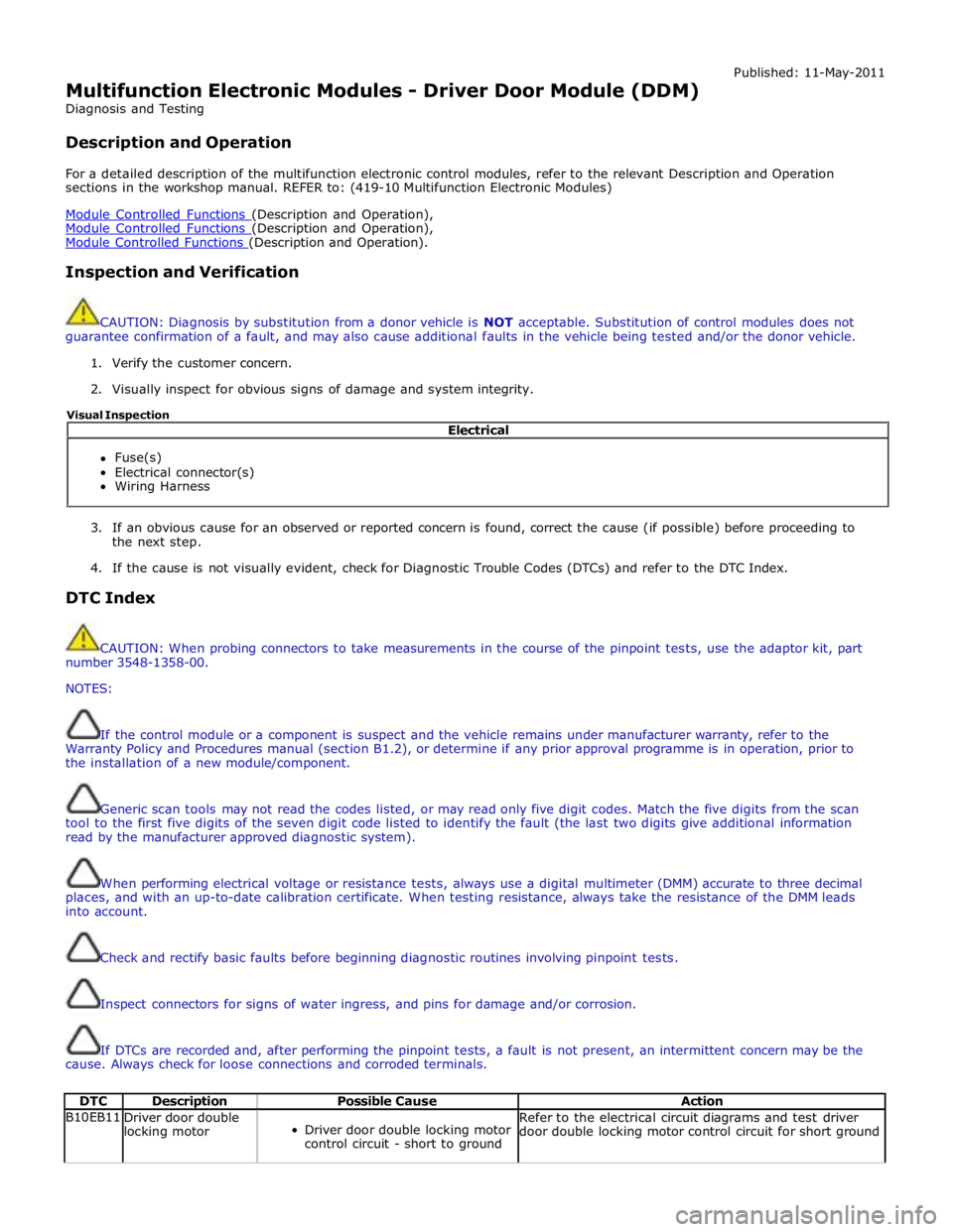
DTC Description Possible Cause Action B10EB11
Driver door double
locking motor
Driver door double locking motor
control circuit - short to ground Refer to the electrical circuit diagrams and test driver
door double locking motor control circuit for short ground Electrical
Fuse(s)
Electrical connector(s)
Wiring Harness Visual Inspection
Page 2178 of 3039
Published: 11-May-2011
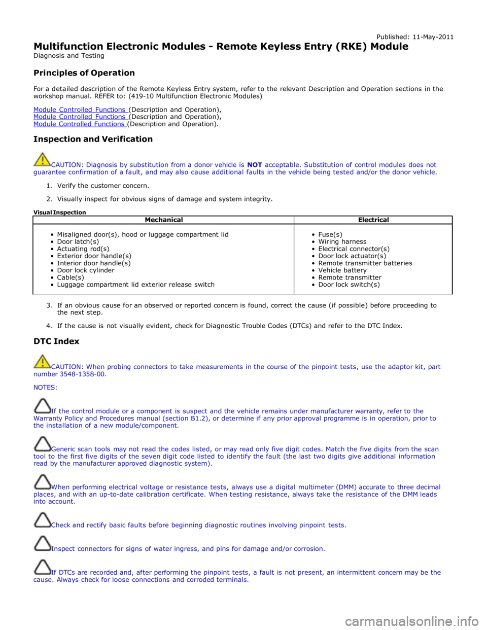
Multifunction Electronic Modules - Remote Keyless Entry (RKE) Module
Diagnosis and Testing
Principles of Operation
For a detailed description of the Remote Keyless Entry system, refer to the relevant Description and Operation sections in the
workshop manual. REFER to: (419-10 Multifunction Electronic Modules)
Module Controlled Functions (Description and Operation), Module Controlled Functions (Description and Operation), Module Controlled Functions (Description and Operation).
Inspection and Verification
CAUTION: Diagnosis by substitution from a donor vehicle is NOT acceptable. Substitution of control modules does not
guarantee confirmation of a fault, and may also cause additional faults in the vehicle being tested and/or the donor vehicle.
1. Verify the customer concern.
2. Visually inspect for obvious signs of damage and system integrity.
Visual Inspection
Mechanical Electrical
Misaligned door(s), hood or luggage compartment lid
Door latch(s)
Actuating rod(s)
Exterior door handle(s)
Interior door handle(s)
Door lock cylinder
Cable(s)
Luggage compartment lid exterior release switch
Fuse(s)
Wiring harness
Electrical connector(s)
Door lock actuator(s)
Remote transmitter batteries
Vehicle battery
Remote transmitter
Door lock switch(s)
3. If an obvious cause for an observed or reported concern is found, correct the cause (if possible) before proceeding to
the next step.
4. If the cause is not visually evident, check for Diagnostic Trouble Codes (DTCs) and refer to the DTC Index.
DTC Index
CAUTION: When probing connectors to take measurements in the course of the pinpoint tests, use the adaptor kit, part
number 3548-1358-00.
NOTES:
If the control module or a component is suspect and the vehicle remains under manufacturer warranty, refer to the
Warranty Policy and Procedures manual (section B1.2), or determine if any prior approval programme is in operation, prior to
the installation of a new module/component.
Generic scan tools may not read the codes listed, or may read only five digit codes. Match the five digits from the scan
tool to the first five digits of the seven digit code listed to identify the fault (the last two digits give additional information
read by the manufacturer approved diagnostic system).
When performing electrical voltage or resistance tests, always use a digital multimeter (DMM) accurate to three decimal
places, and with an up-to-date calibration certificate. When testing resistance, always take the resistance of the DMM leads
into account.
Check and rectify basic faults before beginning diagnostic routines involving pinpoint tests.
Inspect connectors for signs of water ingress, and pins for damage and/or corrosion.
If DTCs are recorded and, after performing the pinpoint tests, a fault is not present, an intermittent concern may be the
cause. Always check for loose connections and corroded terminals.