2010 JAGUAR XFR list
[x] Cancel search: listPage 1940 of 3039
Check and rectify basic faults before beginning diagnostic routines involving pinpoint tests.
If DTCs are recorded and, after performing the pinpoint tests, a fault is not present, an intermittent concern may be the
cause. Always check for loose connections and corroded terminals.
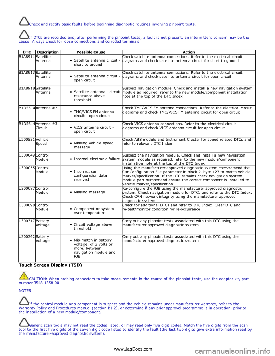
DTC Description Possible Cause Action B1A8911
Satellite
Antenna
Satellite antenna circuit -
short to ground Check satellite antenna connections. Refer to the electrical circuit
diagrams and check satellite antenna circuit for short to ground B1A8913
Satellite
Antenna
Satellite antenna circuit -
open circuit Check satellite antenna connections. Refer to the electrical circuit
diagrams and check satellite antenna circuit for open circuit B1A891B
Satellite
Antenna
Satellite antenna - circuit
resistance above
threshold Suspect navigation module. Check and install a new navigation system
module as required, refer to the new module/component installation
note at the top of the DTC Index B1D5514 Antenna #2
TMC/VICS FM antenna
circuit - open circuit Check TMC/VICS FM antenna connections. Refer to the electrical circuit
diagrams and check TMC/VICS FM antenna circuit for open circuit B1D5614
Antenna #3
Circuit
VICS antenna circuit -
open circuit Check VICS antenna connections. Refer to the electrical circuit
diagrams and check VICS antenna circuit for open circuit U200531
Vehicle
Speed
Missing vehicle speed
message Check ABS module and Instrument Cluster for speed related DTCs and
refer to relevant DTC Index U300049
Control
Module
Internal electronic failure Suspect the navigation module. Check and install a new navigation
system module as required, refer to the new module/component
installation note at the top of the DTC Index U300055
Control
Module
Incorrect car
configuration data
received Using the manufacturer approved diagnostic system check/amend the
Car Configuration File parameter in block 2, byte 127 to match vehicle
market/specification. If the DTC remains check navigation system
module part number and ensure the correct component is installed to
vehicle market/specification U300087
Control
Module
Missing message Re-configure the RJB using the manufacturer approved diagnostic
system. Check navigation module for DTCs and refer to the DTC Index.
Check CAN network integrity using the manufacturer approved diagnostic system U300098
Control
Module
Component or system
over temperature Check for additional DTCs and refer to DTC Index. Clear DTC and
re-test/monitor condition for re-occurrence U300317
Battery
Voltage
Circuit voltage above
threshold Carry out any pinpoint tests associated with this DTC using the
manufacturer approved diagnostic system U300362
Battery
Voltage
Mis-match in battery
voltage, of 2 volts or
more, between
navigation module and
RJB Carry out any pinpoint tests associated with this DTC using the
manufacturer approved diagnostic system Touch Screen Display (TSD)
CAUTION: When probing connectors to take measurements in the course of the pinpoint tests, use the adaptor kit, part
number 3548-1358-00
NOTES:
If the control module or a component is suspect and the vehicle remains under manufacturer warranty, refer to the
Warranty Policy and Procedures manual (section B1.2), or determine if any prior approval programme is in operation, prior to
the installation of a new module/component.
Generic scan tools may not read the codes listed, or may read only five digit codes. Match the five digits from the scan
tool to the first five digits of the seven digit code listed to identify the fault (the last two digits give extra information read by
the manufacturer-approved diagnostic system).
www.JagDocs.com
Page 1952 of 3039
automatically detects the CD format of the source (standard CD, MP3 or WMA files) and offers a full range of options, presenting folders on the touch-screen, listed by albums and tracks, to browse as on a PC. Both versions have mix and repeat
functions and the six-disc version displays disc names.
The IAM communicates on the MOST system with the rest of the audio system. If the IAM is replaced it must be configured as
a new module using the Jaguar approved diagnostic equipment.
Calibration of the IAM using the Jaguar approved diagnostic equipment enables updates to be downloaded as new technology
becomes available or any fault concerns require software updates.
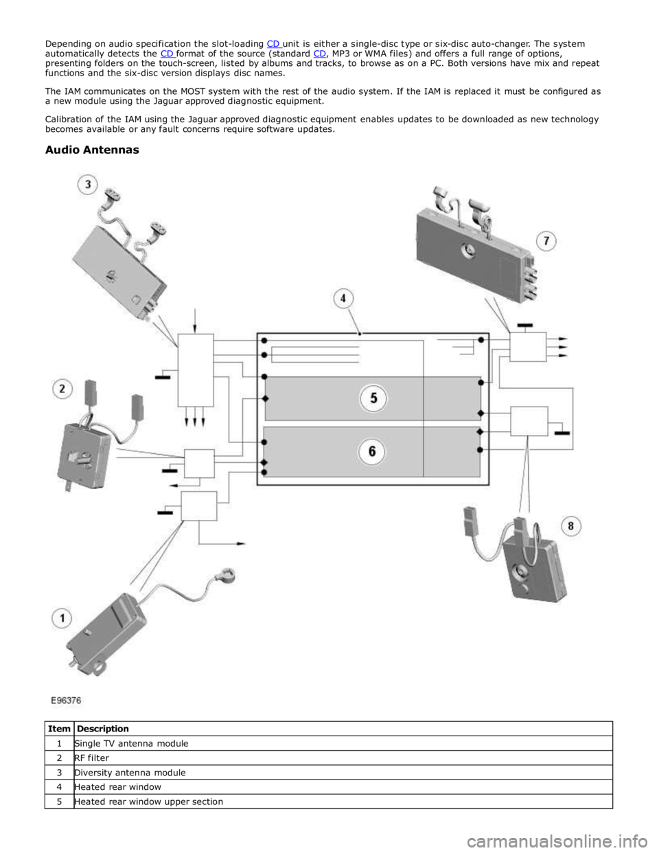
Audio Antennas
Item Description 1 Single TV antenna module 2 RF filter 3 Diversity antenna module 4 Heated rear window 5 Heated rear window upper section
Page 1956 of 3039
controlled through the device itself.
NOTE: The system will support devices with a storage capacity up to 256 GB which is approximately 65,000 audio tracks.
The wiring link harness between the portable audio module and interface panel consists of hardwired and digital connections
for data and signal exchange. The MOST carries the communication signals and information between the portable audio module
to the IAM and touch-screen. Audio output to the speaker system is controlled by the IAM or power amplifier depending on the
audio system specification.
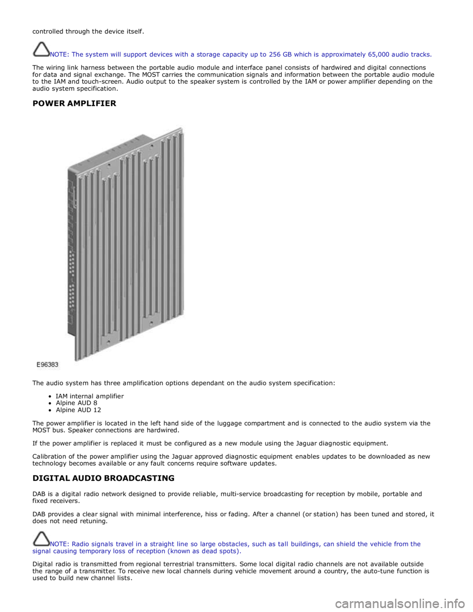
POWER AMPLIFIER
The audio system has three amplification options dependant on the audio system specification:
IAM internal amplifier
Alpine AUD 8
Alpine AUD 12
The power amplifier is located in the left hand side of the luggage compartment and is connected to the audio system via the
MOST bus. Speaker connections are hardwired.
If the power amplifier is replaced it must be configured as a new module using the Jaguar diagnostic equipment.
Calibration of the power amplifier using the Jaguar approved diagnostic equipment enables updates to be downloaded as new
technology becomes available or any fault concerns require software updates.
DIGITAL AUDIO BROADCASTING
DAB is a digital radio network designed to provide reliable, multi-service broadcasting for reception by mobile, portable and
fixed receivers.
DAB provides a clear signal with minimal interference, hiss or fading. After a channel (or station) has been tuned and stored, it
does not need retuning.
NOTE: Radio signals travel in a straight line so large obstacles, such as tall buildings, can shield the vehicle from the
signal causing temporary loss of reception (known as dead spots).
Digital radio is transmitted from regional terrestrial transmitters. Some local digital radio channels are not available outside
the range of a transmitter. To receive new local channels during vehicle movement around a country, the auto-tune function is
used to build new channel lists.
Page 1977 of 3039
In addition to the standard navigation system there are two market dependant systems that supply extra information to the
navigation system and the driver. These are:
TMC (traffic message channel) (Europe only)
VICS (vehicle information and communication system) (Japan only)
The TMC (traffic message channel) is a function of the FM (frequency modulation)RDS (radio data system). The system
broadcasts real-time traffic and weather information. Data messages are received and decoded by the TMC (traffic message
channel) integral receiver and processed by the navigation computer. TMC (traffic message channel) messages can be filtered
by the navigation computer so that only those relevant to the current journey are displayed, allowing the navigation system to
offer dynamic route guidance - alerting the driver of a problem on the planned route and calculating an alternative route to
avoid the incident. All TMC (traffic message channel) events on the map can be viewed not just the ones on the calculated
route.
TMC (traffic message channel) traffic information systems conform to a global standard that has been adopted by traffic data
gatherers, information service providers, broadcasters and vehicle/receiver manufacturers.
All TMC (traffic message channel) receivers use the same list of event codes, while the location database (on the map disc)
contains both a country-specific set of location codes for the strategic European road network.
TMC (traffic message channel) traffic data is currently broadcast in many European countries.
The VICS (vehicle information and communication system) is broadcast in the Japanese market.
The VICS (vehicle information and communication system) supplies information to enable the navigation computer to re-route
the navigation guidance or to inform the vehicle driver of traffic conditions in the vehicles vicinity. Information is provided to
the system through 3 routes:
RF (radio frequency) transmission
Infra-red transmission
FM multiplex transmissions
The RF (radio frequency) transmissions are generally transmitted from road side beacons mainly on expressways. The
information transmitted is as follows:
Traffic congestion
Travel time to next intersection
Traffic conditions in surrounding areas and expressway turn offs
Traffic accidents
Speed limits
Lane regulations
Tire change
Parking availability at expressway service areas and parking areas
Infra-Red transmissions are transmitted from road side beacons on major trunk roads. The information transmitted is:
Traffic congestion and travel time
Traffic accidents
Breakdowns
Road works restrictions
Parking availability
FM transmissions are broadcast as part of the FM multiplex broadcasting system from NHK FM stations. Information transmitted is:
Traffic congestion and travel time for wide areas
Traffic accidents, road works, speed limits and lane restrictions for a wide area
Parking availability information
The traffic data is split from the normal FM transmissions by the diversity antenna module.
Selection of 'Navigation' on the Touch-screen home menu and subsequent sub-menu selection sends a control request signal to
the navigation computer on the MOST (media orientated systems transport) ring. The requested control information is
processed by the navigation computer.
If voice guidance is operational the voice signal information is relayed from the navigation computer on the MOST (media
orientated systems transport) ring to either the IAM (integrated audio unit) or Power Amplifier, dependant on equipment level,
for output on the speaker system. The navigation audio output is through the front speakers whilst the background audio, for
example radio or CD (compact disc), is played at a reduced volume on the rear speakers.
The GPS signal is available to the navigation system at all times when the vehicle ignition is switched on.
Navigation user voice commands are made using the JaguarVoice system. The ICM (information control module) processes the
analogue signal from the JaguarVoice switch into a digital signal. The digital signal is passed from the ICM (information control
module) onto the MOST (media orientated systems transport) system to the JaguarVoice control unit which is integral with the
navigation computer.
The navigation computer sends an instruction via the MOST (media orientated systems transport) ring to the IAM (integrated
audio module) to turn on the microphone facility.
The microphone is hardwired to the IAM (integrated audio module). The spoken voice command signals are relayed from the
IAM (integrated audio module) via the MOST (media orientated systems transport) ring to the navigation computer for
Page 2018 of 3039
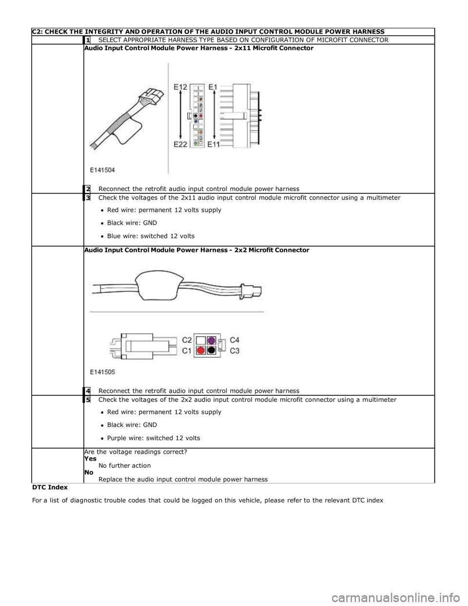
C2: CHECK THE INTEGRITY AND OPERATION OF THE AUDIO INPUT CONTROL MODULE POWER HARNESS 1 SELECT APPROPRIATE HARNESS TYPE BASED ON CONFIGURATION OF MICROFIT CONNECTOR Audio Input Control Module Power Harness - 2x11 Microfit Connector
2 Reconnect the retrofit audio input control module power harness 3 Check the voltages of the 2x11 audio input control module microfit connector using a multimeter Red wire: permanent 12 volts supply
Black wire: GND
Blue wire: switched 12 volts Audio Input Control Module Power Harness - 2x2 Microfit Connector
4 Reconnect the retrofit audio input control module power harness 5 Check the voltages of the 2x2 audio input control module microfit connector using a multimeter Red wire: permanent 12 volts supply
Black wire: GND
Purple wire: switched 12 volts Are the voltage readings correct?
Yes
No further action
No
Replace the audio input control module power harness DTC Index
For a list of diagnostic trouble codes that could be logged on this vehicle, please refer to the relevant DTC index
Page 2038 of 3039
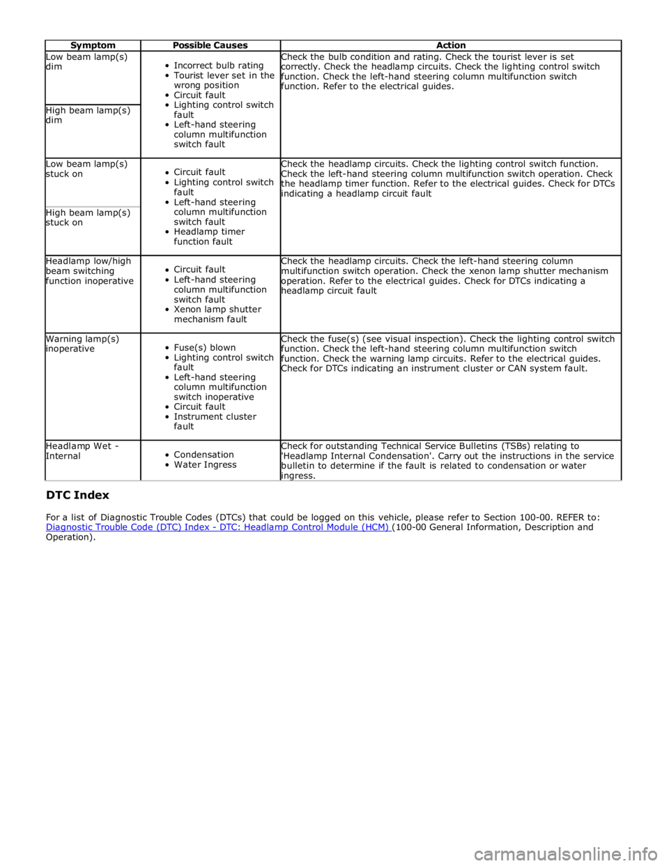
Symptom Possible Causes Action Low beam lamp(s)
dim
Incorrect bulb rating
Tourist lever set in the
wrong position
Circuit fault
Lighting control switch
fault
Left-hand steering
column multifunction
switch fault Check the bulb condition and rating. Check the tourist lever is set
correctly. Check the headlamp circuits. Check the lighting control switch
function. Check the left-hand steering column multifunction switch
function. Refer to the electrical guides. High beam lamp(s)
dim Low beam lamp(s)
stuck on
Circuit fault
Lighting control switch
fault
Left-hand steering
column multifunction
switch fault
Headlamp timer
function fault Check the headlamp circuits. Check the lighting control switch function.
Check the left-hand steering column multifunction switch operation. Check
the headlamp timer function. Refer to the electrical guides. Check for DTCs
indicating a headlamp circuit fault High beam lamp(s)
stuck on Headlamp low/high
beam switching
function inoperative
Circuit fault
Left-hand steering
column multifunction
switch fault
Xenon lamp shutter
mechanism fault Check the headlamp circuits. Check the left-hand steering column
multifunction switch operation. Check the xenon lamp shutter mechanism
operation. Refer to the electrical guides. Check for DTCs indicating a
headlamp circuit fault Warning lamp(s)
inoperative
Fuse(s) blown
Lighting control switch
fault
Left-hand steering
column multifunction
switch inoperative
Circuit fault
Instrument cluster
fault Check the fuse(s) (see visual inspection). Check the lighting control switch
function. Check the left-hand steering column multifunction switch
function. Check the warning lamp circuits. Refer to the electrical guides.
Check for DTCs indicating an instrument cluster or CAN system fault. Headlamp Wet -
Internal
Condensation
Water Ingress Check for outstanding Technical Service Bulletins (TSBs) relating to
'Headlamp Internal Condensation'. Carry out the instructions in the service
bulletin to determine if the fault is related to condensation or water ingress. DTC Index
For a list of Diagnostic Trouble Codes (DTCs) that could be logged on this vehicle, please refer to Section 100-00. REFER to:
Diagnostic Trouble Code (DTC) Index - DTC: Headlamp Control Module (HCM) (100-00 General Information, Description and Operation).
Page 2063 of 3039
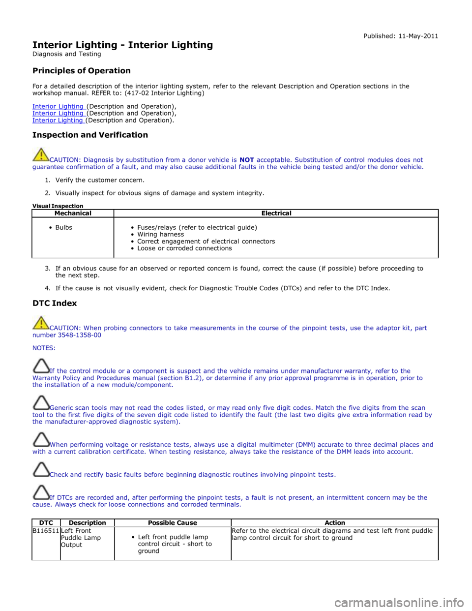
Interior Lighting - Interior Lighting
Diagnosis and Testing
Principles of Operation Published: 11-May-2011
For a detailed description of the interior lighting system, refer to the relevant Description and Operation sections in the
workshop manual. REFER to: (417-02 Interior Lighting)
Interior Lighting (Description and Operation), Interior Lighting (Description and Operation), Interior Lighting (Description and Operation).
Inspection and Verification
CAUTION: Diagnosis by substitution from a donor vehicle is NOT acceptable. Substitution of control modules does not
guarantee confirmation of a fault, and may also cause additional faults in the vehicle being tested and/or the donor vehicle.
1. Verify the customer concern.
2. Visually inspect for obvious signs of damage and system integrity.
Visual Inspection
Mechanical Electrical
Bulbs
Fuses/relays (refer to electrical guide)
Wiring harness
Correct engagement of electrical connectors
Loose or corroded connections
3. If an obvious cause for an observed or reported concern is found, correct the cause (if possible) before proceeding to
the next step.
4. If the cause is not visually evident, check for Diagnostic Trouble Codes (DTCs) and refer to the DTC Index.
DTC Index
CAUTION: When probing connectors to take measurements in the course of the pinpoint tests, use the adaptor kit, part
number 3548-1358-00
NOTES:
If the control module or a component is suspect and the vehicle remains under manufacturer warranty, refer to the
Warranty Policy and Procedures manual (section B1.2), or determine if any prior approval programme is in operation, prior to
the installation of a new module/component.
Generic scan tools may not read the codes listed, or may read only five digit codes. Match the five digits from the scan
tool to the first five digits of the seven digit code listed to identify the fault (the last two digits give extra information read by
the manufacturer-approved diagnostic system).
When performing voltage or resistance tests, always use a digital multimeter (DMM) accurate to three decimal places and
with a current calibration certificate. When testing resistance, always take the resistance of the DMM leads into account.
Check and rectify basic faults before beginning diagnostic routines involving pinpoint tests.
If DTCs are recorded and, after performing the pinpoint tests, a fault is not present, an intermittent concern may be the
cause. Always check for loose connections and corroded terminals.
DTC Description Possible Cause Action B116511
Left Front
Puddle Lamp
Output
Left front puddle lamp
control circuit - short to
ground Refer to the electrical circuit diagrams and test left front puddle
lamp control circuit for short to ground
Page 2078 of 3039
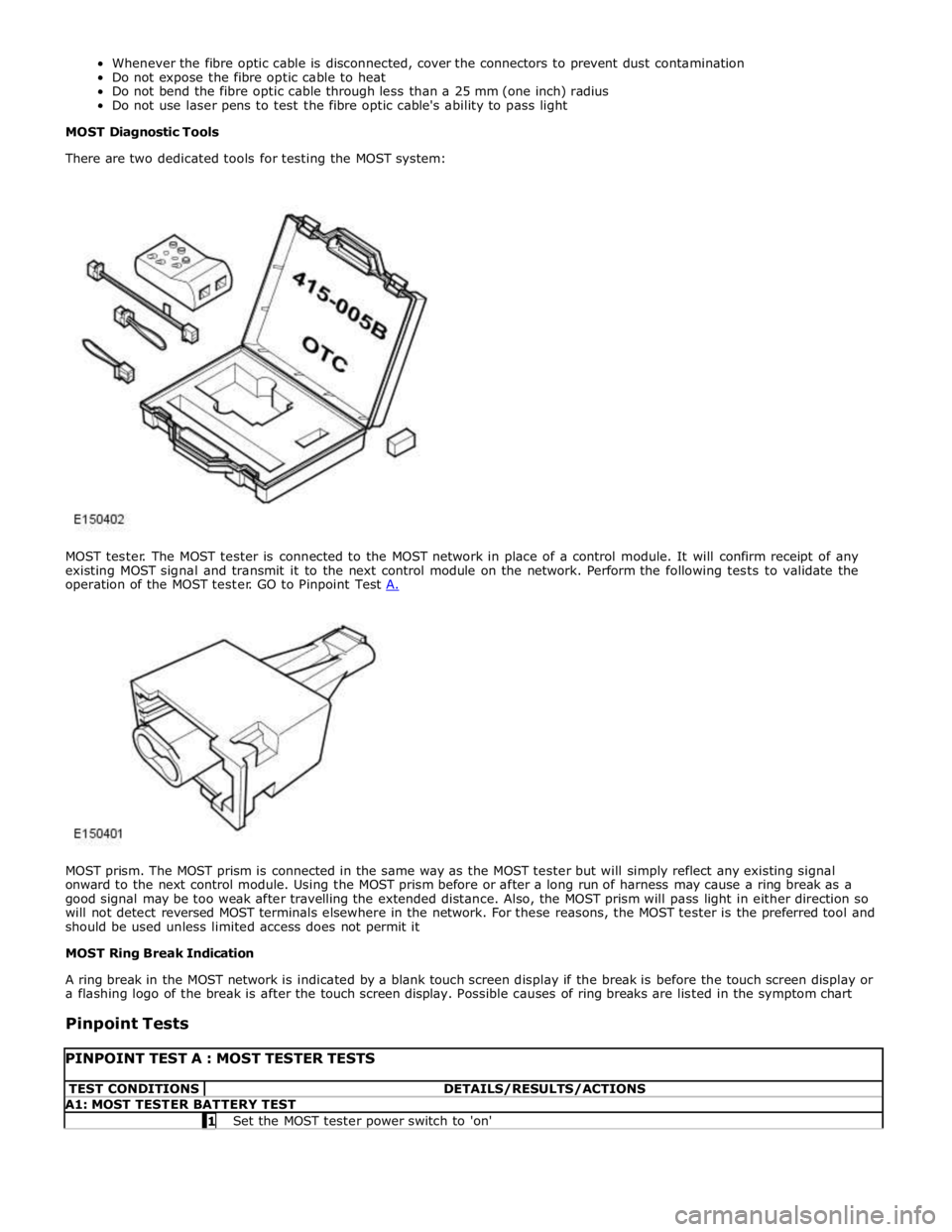
MOST prism. The MOST prism is connected in the same way as the MOST tester but will simply reflect any existing signal
onward to the next control module. Using the MOST prism before or after a long run of harness may cause a ring break as a
good signal may be too weak after travelling the extended distance. Also, the MOST prism will pass light in either direction so
will not detect reversed MOST terminals elsewhere in the network. For these reasons, the MOST tester is the preferred tool and
should be used unless limited access does not permit it
MOST Ring Break Indication
A ring break in the MOST network is indicated by a blank touch screen display if the break is before the touch screen display or
a flashing logo of the break is after the touch screen display. Possible causes of ring breaks are listed in the symptom chart
Pinpoint Tests
PINPOINT TEST A : MOST TESTER TESTS TEST CONDITIONS DETAILS/RESULTS/ACTIONS A1: MOST TESTER BATTERY TEST 1 Set the MOST tester power switch to 'on'