2010 JAGUAR XFR list
[x] Cancel search: listPage 2342 of 3039
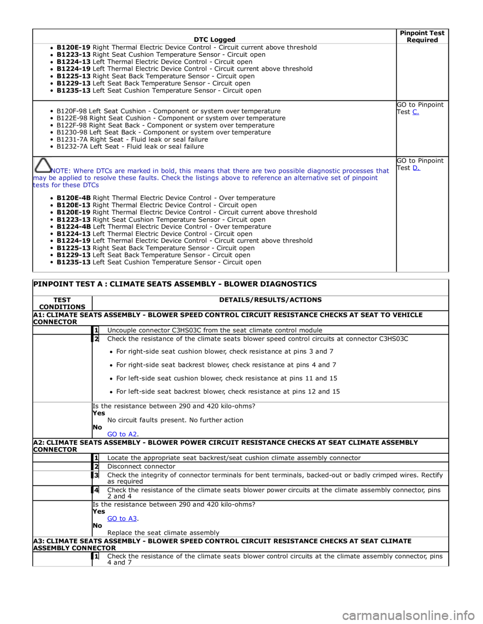
DTC Logged Pinpoint Test Required B120E-19 Right Thermal Electric Device Control - Circuit current above threshold
B1223-13 Right Seat Cushion Temperature Sensor - Circuit open
B1224-13 Left Thermal Electric Device Control - Circuit open
B1224-19 Left Thermal Electric Device Control - Circuit current above threshold
B1225-13 Right Seat Back Temperature Sensor - Circuit open
B1229-13 Left Seat Back Temperature Sensor - Circuit open
B1235-13 Left Seat Cushion Temperature Sensor - Circuit open
B120F-98 Left Seat Cushion - Component or system over temperature
B122E-98 Right Seat Cushion - Component or system over temperature
B122F-98 Right Seat Back - Component or system over temperature
B1230-98 Left Seat Back - Component or system over temperature
B1231-7A Right Seat - Fluid leak or seal failure
B1232-7A Left Seat - Fluid leak or seal failure GO to Pinpoint
Test C.
NOTE: Where DTCs are marked in bold, this means that there are two possible diagnostic processes that
may be applied to resolve these faults. Check the listings above to reference an alternative set of pinpoint
tests for these DTCs
B120E-4B Right Thermal Electric Device Control - Over temperature
B120E-13 Right Thermal Electric Device Control - Circuit open
B120E-19 Right Thermal Electric Device Control - Circuit current above threshold
B1223-13 Right Seat Cushion Temperature Sensor - Circuit open
B1224-4B Left Thermal Electric Device Control - Over temperature
B1224-13 Left Thermal Electric Device Control - Circuit open
B1224-19 Left Thermal Electric Device Control - Circuit current above threshold
B1225-13 Right Seat Back Temperature Sensor - Circuit open
B1229-13 Left Seat Back Temperature Sensor - Circuit open
B1235-13 Left Seat Cushion Temperature Sensor - Circuit open GO to Pinpoint
Test D.
PINPOINT TEST A : CLIMATE SEATS ASSEMBLY - BLOWER DIAGNOSTICS TEST
CONDITIONS DETAILS/RESULTS/ACTIONS A1: CLIMATE SEATS ASSEMBLY - BLOWER SPEED CONTROL CIRCUIT RESISTANCE CHECKS AT SEAT TO VEHICLE
CONNECTOR 1 Uncouple connector C3HS03C from the seat climate control module 2 Check the resistance of the climate seats blower speed control circuits at connector C3HS03C For right-side seat cushion blower, check resistance at pins 3 and 7
For right-side seat backrest blower, check resistance at pins 4 and 7
For left-side seat cushion blower, check resistance at pins 11 and 15
For left-side seat backrest blower, check resistance at pins 12 and 15 Is the resistance between 290 and 420 kilo-ohms? Yes
No circuit faults present. No further action
No
GO to A2. A2: CLIMATE SEATS ASSEMBLY - BLOWER POWER CIRCUIT RESISTANCE CHECKS AT SEAT CLIMATE ASSEMBLY
CONNECTOR 1 Locate the appropriate seat backrest/seat cushion climate assembly connector 2 Disconnect connector 3 Check the integrity of connector terminals for bent terminals, backed-out or badly crimped wires. Rectify as required 4 Check the resistance of the climate seats blower power circuits at the climate assembly connector, pins 2 and 4 Is the resistance between 290 and 420 kilo-ohms? Yes
GO to A3. No
Replace the seat climate assembly A3: CLIMATE SEATS ASSEMBLY - BLOWER SPEED CONTROL CIRCUIT RESISTANCE CHECKS AT SEAT CLIMATE
ASSEMBLY CONNECTOR 1 Check the resistance of the climate seats blower control circuits at the climate assembly connector, pins 4 and 7
Page 2345 of 3039
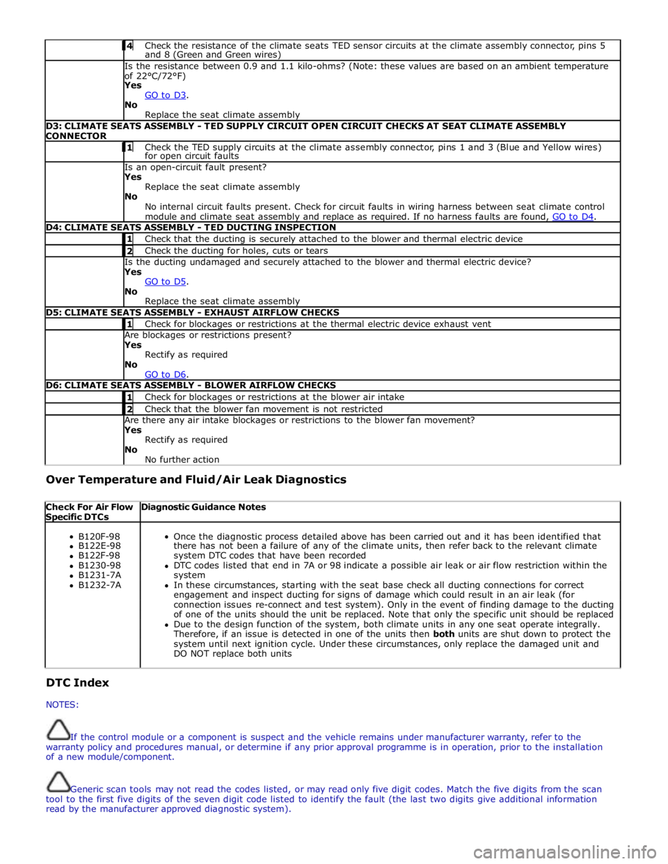
4 Check the resistance of the climate seats TED sensor circuits at the climate assembly connector, pins 5 and 8 (Green and Green wires) Is the resistance between 0.9 and 1.1 kilo-ohms? (Note: these values are based on an ambient temperature
of 22°C/72°F)
Yes
GO to D3. No
Replace the seat climate assembly D3: CLIMATE SEATS ASSEMBLY - TED SUPPLY CIRCUIT OPEN CIRCUIT CHECKS AT SEAT CLIMATE ASSEMBLY
CONNECTOR 1 Check the TED supply circuits at the climate assembly connector, pins 1 and 3 (Blue and Yellow wires) for open circuit faults Is an open-circuit fault present?
Yes
Replace the seat climate assembly
No
No internal circuit faults present. Check for circuit faults in wiring harness between seat climate control
module and climate seat assembly and replace as required. If no harness faults are found, GO to D4. D4: CLIMATE SEATS ASSEMBLY - TED DUCTING INSPECTION 1 Check that the ducting is securely attached to the blower and thermal electric device 2 Check the ducting for holes, cuts or tears Is the ducting undamaged and securely attached to the blower and thermal electric device?
Yes
GO to D5. No
Replace the seat climate assembly D5: CLIMATE SEATS ASSEMBLY - EXHAUST AIRFLOW CHECKS 1 Check for blockages or restrictions at the thermal electric device exhaust vent Are blockages or restrictions present?
Yes
Rectify as required
No
GO to D6. D6: CLIMATE SEATS ASSEMBLY - BLOWER AIRFLOW CHECKS 1 Check for blockages or restrictions at the blower air intake 2 Check that the blower fan movement is not restricted Are there any air intake blockages or restrictions to the blower fan movement?
Yes
Rectify as required
No
No further action Over Temperature and Fluid/Air Leak Diagnostics
Check For Air Flow Specific DTCs Diagnostic Guidance Notes
B120F-98
Once the diagnostic process detailed above has been carried out and it has been identified that B122E-98 there has not been a failure of any of the climate units, then refer back to the relevant climate B122F-98 system DTC codes that have been recorded B1230-98 DTC codes listed that end in 7A or 98 indicate a possible air leak or air flow restriction within the B1231-7A system B1232-7A In these circumstances, starting with the seat base check all ducting connections for correct engagement and inspect ducting for signs of damage which could result in an air leak (for connection issues re-connect and test system). Only in the event of finding damage to the ducting of one of the units should the unit be replaced. Note that only the specific unit should be replaced Due to the design function of the system, both climate units in any one seat operate integrally. Therefore, if an issue is detected in one of the units then both units are shut down to protect the system until next ignition cycle. Under these circumstances, only replace the damaged unit and DO NOT replace both units DTC Index
NOTES:
If the control module or a component is suspect and the vehicle remains under manufacturer warranty, refer to the
warranty policy and procedures manual, or determine if any prior approval programme is in operation, prior to the installation
of a new module/component.
Generic scan tools may not read the codes listed, or may read only five digit codes. Match the five digits from the scan
tool to the first five digits of the seven digit code listed to identify the fault (the last two digits give additional information
read by the manufacturer approved diagnostic system).
Page 2418 of 3039
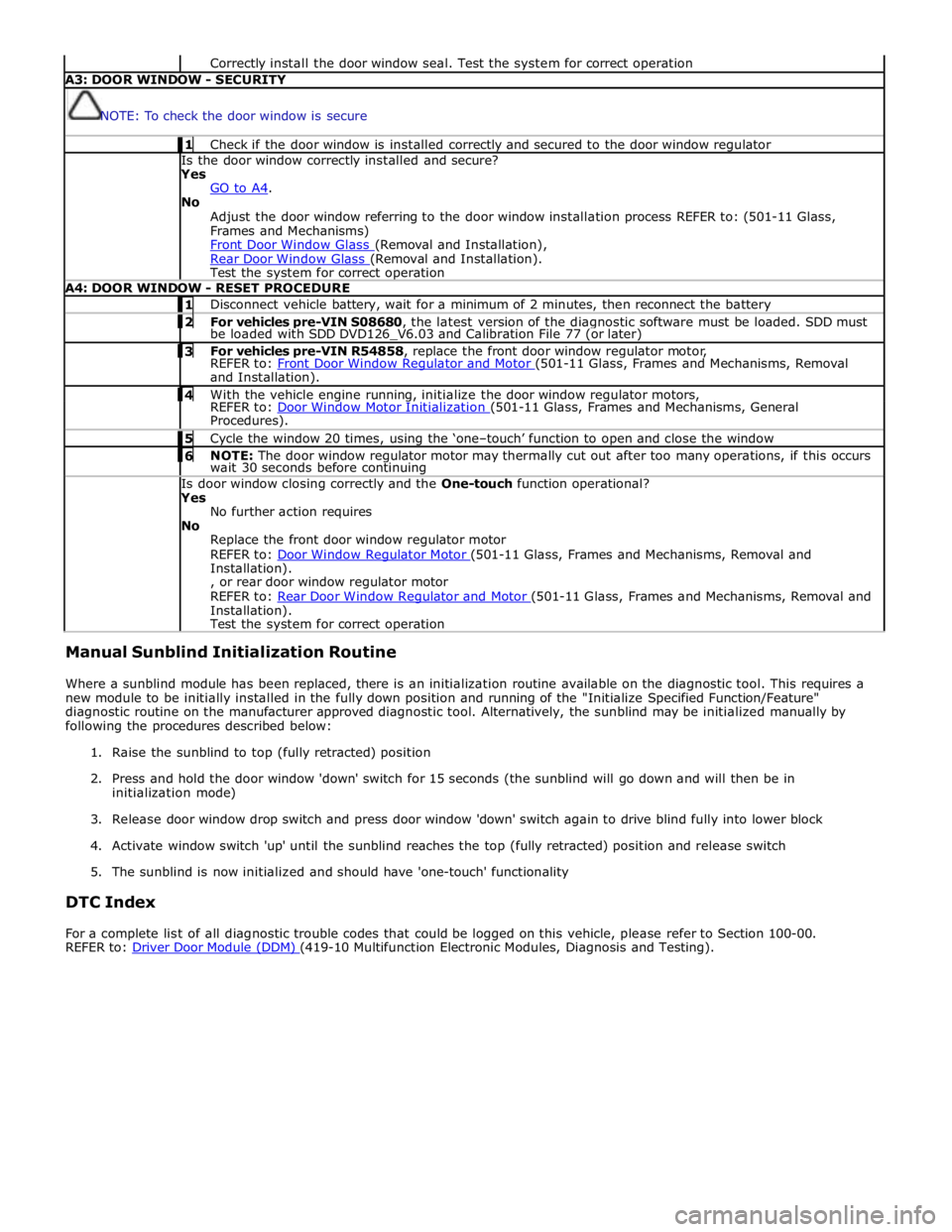
Correctly install the door window seal. Test the system for correct operation A3: DOOR WINDOW - SECURITY
NOTE: To check the door window is secure 1 Check if the door window is installed correctly and secured to the door window regulator Is the door window correctly installed and secure?
Yes
GO to A4. No
Adjust the door window referring to the door window installation process REFER to: (501-11 Glass,
Frames and Mechanisms)
Front Door Window Glass (Removal and Installation), Rear Door Window Glass (Removal and Installation). Test the system for correct operation A4: DOOR WINDOW - RESET PROCEDURE 1 Disconnect vehicle battery, wait for a minimum of 2 minutes, then reconnect the battery 2 For vehicles pre-VIN S08680, the latest version of the diagnostic software must be loaded. SDD must be loaded with SDD DVD126_V6.03 and Calibration File 77 (or later) 3 For vehicles pre-VIN R54858, replace the front door window regulator motor, REFER to: Front Door Window Regulator and Motor (501-11 Glass, Frames and Mechanisms, Removal and Installation). 4 With the vehicle engine running, initialize the door window regulator motors, REFER to: Door Window Motor Initialization (501-11 Glass, Frames and Mechanisms, General Procedures). 5 Cycle the window 20 times, using the ‘one–touch’ function to open and close the window 6 NOTE: The door window regulator motor may thermally cut out after too many operations, if this occurs wait 30 seconds before continuing Is door window closing correctly and the One-touch function operational?
Yes
No further action requires
No
Replace the front door window regulator motor
REFER to: Door Window Regulator Motor (501-11 Glass, Frames and Mechanisms, Removal and Installation).
, or rear door window regulator motor
REFER to: Rear Door Window Regulator and Motor (501-11 Glass, Frames and Mechanisms, Removal and Installation).
Test the system for correct operation Manual Sunblind Initialization Routine
Where a sunblind module has been replaced, there is an initialization routine available on the diagnostic tool. This requires a
new module to be initially installed in the fully down position and running of the "Initialize Specified Function/Feature"
diagnostic routine on the manufacturer approved diagnostic tool. Alternatively, the sunblind may be initialized manually by
following the procedures described below:
1. Raise the sunblind to top (fully retracted) position
2. Press and hold the door window 'down' switch for 15 seconds (the sunblind will go down and will then be in
initialization mode)
3. Release door window drop switch and press door window 'down' switch again to drive blind fully into lower block
4. Activate window switch 'up' until the sunblind reaches the top (fully retracted) position and release switch
5. The sunblind is now initialized and should have 'one-touch' functionality
DTC Index
For a complete list of all diagnostic trouble codes that could be logged on this vehicle, please refer to Section 100-00.
REFER to: Driver Door Module (DDM) (419-10 Multifunction Electronic Modules, Diagnosis and Testing).
Page 2421 of 3039
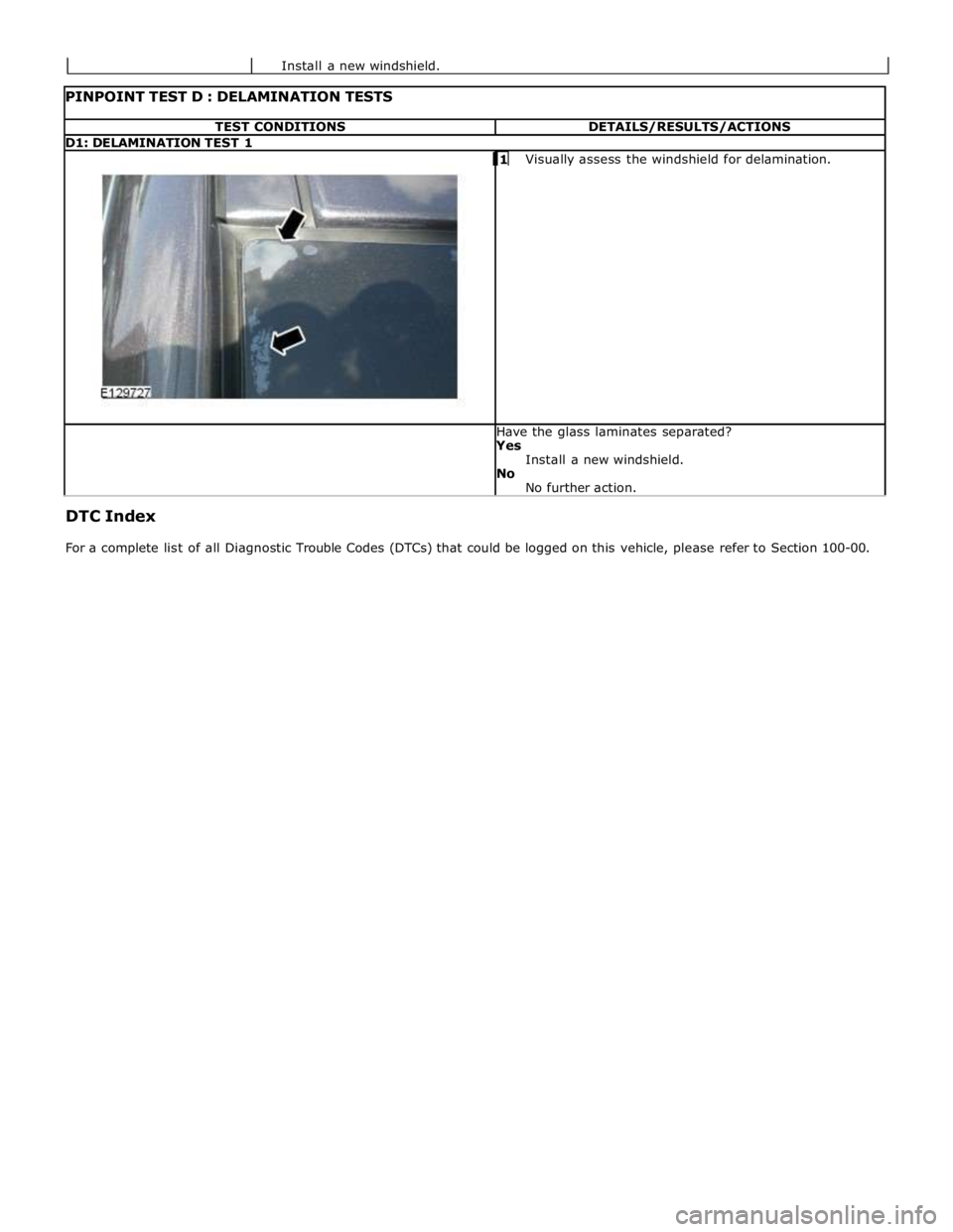
TEST CONDITIONS DETAILS/RESULTS/ACTIONS D1: DELAMINATION TEST 1
1 Visually assess the windshield for delamination. Have the glass laminates separated?
Yes
Install a new windshield.
No
No further action. DTC Index
For a complete list of all Diagnostic Trouble Codes (DTCs) that could be logged on this vehicle, please refer to Section 100-00. Install a new windshield.
Page 2496 of 3039
Symptom Possible Causes Action outside (but opens from the
inside) GO to Pinpoint Test A. Door(s) will not unlatch/open when
using inside door handle
Child lock(s) engaged
Interior door handle
condition/installation
Interior release cable disconnected
from interior door handle or door
latch
Check that the child locks are
disengaged
Check the interior door handle
condition and installation
Check the condition and security of
the interior release cable
Single Door Will Not Open From
The Inside (but opens from the
outside) GO to Pinpoint Test B. Door(s) will not lock/unlock from key
fob, key or internal lock switch
Wiring harness/connectors
Central junction box (CJB)
Door lock switch
Cable fault
Check for relevant stored DTCs
Once any DTC related faults have
been rectified continue with the
diagnostic steps below
No lock / unlock function from
key-fob GO to Pinpoint Test C. Door ajar or miss lock signal at
message centre when door(s) are
closed or alarm triggering
Wiring harness
Instrument cluster
Incorrect striker
alignment/adjustment
Ajar switch circuit short circuit to
ground
Ajar switch failure
Latch Mounted Door Ajar Switch
Test GO to Pinpoint Test D. DTC Index
For a list of Diagnostic Trouble Codes (DTCs) that could be logged on this vehicle, please refer to Section 100-00.
REFER to: Communications Network (418-00, Diagnosis and Testing) /
Locks, Latches and Entry Systems - DTC: With (501-14, Diagnosis and Testing).
Pinpoint Test
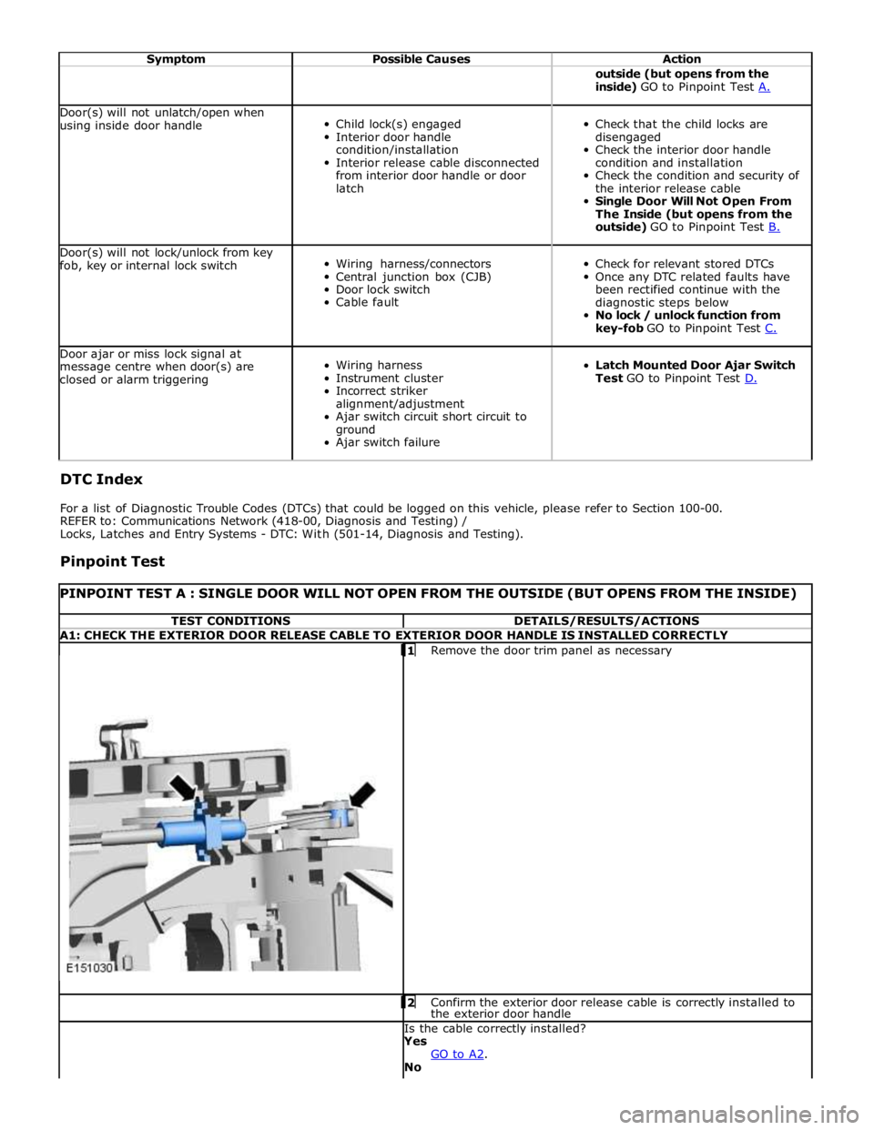
PINPOINT TEST A : SINGLE DOOR WILL NOT OPEN FROM THE OUTSIDE (BUT OPENS FROM THE INSIDE) TEST CONDITIONS DETAILS/RESULTS/ACTIONS A1: CHECK THE EXTERIOR DOOR RELEASE CABLE TO EXTERIOR DOOR HANDLE IS INSTALLED CORRECTLY
1 Remove the door trim panel as necessary 2 Confirm the exterior door release cable is correctly installed to the exterior door handle Is the cable correctly installed?
Yes
GO to A2. No
Page 2543 of 3039
Wipers and Washers - Wipers and Washers
Diagnosis and Testing
Principle of Operation Published: 11-May-2011
For a detailed description of the wipers and washers, refer to the relevant Description and Operation sections in the workshop
manual. REFER to: (501-16 Wipers and Washers)
Wipers and Washers (Description and Operation), Wipers and Washers (Description and Operation), Wipers and Washers (Description and Operation).
Inspection and Verification
CAUTION: Diagnosis by substitution from a donor vehicle is NOT acceptable. Substitution of control modules does not
guarantee confirmation of a fault, and may also cause additional faults in the vehicle being tested and/or the donor vehicle.
1. Verify the customer concern.
2. Visually inspect for obvious signs of damage and system integrity.
Visual Inspection
Mechanical Electrical
Wiper blade(s)
Wiper pivot arm shaft
Washer reservoir
Hose(s)
Washer jet(s)
Fuse(s)
Wiring harness
Electrical connector(s)
Washer pump(s)
Wiper motor
3. If an obvious cause for an observed or reported concern is found, correct the cause (if possible) before proceeding to
the next step.
4. If the cause is not visually evident, check for Diagnostic Trouble Codes (DTCs) and refer to the DTC Index.
DTC Index
CAUTION: When probing connectors to take measurements in the course of the pinpoint tests, use the adaptor kit, part
number 3548-1358-00.
NOTES:
If the control module or a component is suspect and the vehicle remains under manufacturer warranty, refer to the
Warranty Policy and Procedures manual (section B1.2), or determine if any prior approval programme is in operation, prior to
the installation of a new module/component.
Generic scan tools may not read the codes listed, or may read only five digit codes. Match the five digits from the scan
tool to the first five digits of the seven digit code listed to identify the fault (the last two digits give additional information
read by the manufacturer approved diagnostic system).
When performing electrical voltage or resistance tests, always use a digital multimeter (DMM) accurate to three decimal
places, and with an up-to-date calibration certificate. When testing resistance, always take the resistance of the DMM leads
into account.
Check and rectify basic faults before beginning diagnostic routines involving pinpoint tests.
Inspect connectors for signs of water ingress, and pins for damage and/or corrosion.
If DTCs are recorded and, after performing the pinpoint tests, a fault is not present, an intermittent concern may be the
cause. Always check for loose connections and corroded terminals.
DTC Description Possible Cause Action B109512
Wiper On/Off
Relay
Wiper On/Off relay control Carry out any pinpoint tests associated with this DTC using the
manufacturer approved diagnostic system. Refer to the electrical
Page 2563 of 3039
Roof Opening Panel - Roof Opening Panel
Diagnosis and Testing
Principle of Operation Published: 11-May-2011
For a detailed description of the roof opening panel, refer to the relevant Description and Operation sections in the workshop
manual. REFER to: (501-17 Roof Opening Panel)
Roof Opening Panel (Description and Operation), Roof Opening Panel (Description and Operation), Roof Opening Panel (Description and Operation).
Inspection and Verification
CAUTION: Diagnosis by substitution from a donor vehicle is NOT acceptable. Substitution of control modules does not
guarantee confirmation of a fault, and may also cause additional faults in the vehicle being tested and/or the donor vehicle.
1. Verify the customer concern.
2. Visually inspect for obvious signs of damage and system integrity.
Visual Inspection
Mechanical Electrical
Roof opening panel
Helixed drive cables
Switch
Control unit/motor
Fuses/relays (refer to electrical guide)
Wiring harness
Correct engagement of electrical connectors
Loose or corroded connections
3. If an obvious cause for an observed or reported concern is found, correct the cause (if possible) before proceeding to
the next step.
4. If the cause is not visually evident, check for Diagnostic Trouble Codes (DTCs) and refer to the DTC Index.
DTC Index
CAUTION: When probing connectors to take measurements in the course of the pinpoint tests, use the adaptor kit, part
number 3548-1358-00.
NOTES:
If the control module or a component is suspect and the vehicle remains under manufacturer warranty, refer to the
Warranty Policy and Procedures manual (section B1.2), or determine if any prior approval programme is in operation, prior to
the installation of a new module/component.
Generic scan tools may not read the codes listed, or may read only five digit codes. Match the five digits from the scan
tool to the first five digits of the seven digit code listed to identify the fault (the last two digits give extra information read by
the manufacturer-approved diagnostic system).
When performing voltage or resistance tests, always use a digital multimeter (DMM) accurate to three decimal places and
with a current calibration certificate. When testing resistance, always take the resistance of the DMM leads into account.
Check and rectify basic faults before beginning diagnostic routines involving pinpoint tests.
If DTCs are recorded and, after performing the pinpoint tests, a fault is not present, an intermittent concern may be the
cause. Always check for loose connections and corroded terminals.
DTC Description Possible Cause Action B10F211 Sunroof Control
Sunroof enable signal
circuit - short to ground Carry out any pinpoint tests associated with this DTC using the
manufacturer approved diagnostic system. Refer to the electrical
circuit diagrams and check sunroof enable signal circuit for short
to ground B10F212 Sunroof Control
Sunroof enable signal
circuit - short to power Refer to the electrical circuit diagrams and check sunroof enable
signal circuit for short to power
Page 2596 of 3039
For a complete list of all diagnostic trouble codes that could be logged on this vehicle, please refer to section 100-00.
REFER to: Supplemental Restraint System (SRS) Health and Safety Precautions (100-00 General Information, Description and Operation) /
Diagnostic Trouble Code (DTC) Index - DTC: Restraints Control Module (RCM) (100-00, Description and Operation).
Symptom Chart for Seatbelt Rows 1, 2
Symptom Possible Causes Action Seatbelt jammed -
Webbing tight
Backlock effect in action (webbing retracted
quickly and came to sudden stop)
Seatbelt retractor not installed correctly
Automatic locking retractor activated (clicking
– during retraction only)
GO to Pinpoint Test A. GO to Pinpoint Test F. See the automatic locking retractor
description below Seatbelt jammed -
Seatbelt webbing trapped in seat
GO to Pinpoint Test B. Webbing loose Seatbelt retractor webbing guide loose GO to Pinpoint Test C. Twist in webbing GO to Pinpoint Test D. Interference in webbing routing GO to Pinpoint Test E. D-loop not rotating correctly GO to Pinpoint Test G. Seatbelt - Intermittent jamming
Seatbelt retractor not installed correctly
GO to Pinpoint Test F. Seatbelt - Slow retraction
Seatbelt retractor webbing guide loose
GO to Pinpoint Test C. Twist in seatbelt webbing GO to Pinpoint Test D. Interference in webbing routing GO to Pinpoint Test E. Seatbelt retractor not installed correctly GO to Pinpoint Test F. D-loop not rotating correctly GO to Pinpoint Test G. Foreign object/debris GO to Pinpoint Test E. Seatbelt - Not retracting
Seatbelt retractor webbing guide loose
GO to Pinpoint Test C. Twist in seatbelt webbing GO to Pinpoint Test D. D-loop not rotating correctly GO to Pinpoint Test G. Interference in webbing routing GO to Pinpoint Test E. Foreign object/debris GO to Pinpoint Test E. Seatbelt - Not extracting
Backlock effect-in action (webbing retracted
GO to Pinpoint Test A. quickly and came to sudden stop) GO to Pinpoint Test F. Seatbelt retractor not installed correctly GO to Pinpoint Test C. Seatbelt retractor webbing guide loose GO to Pinpoint Test D. Twist in seatbelt webbing GO to Pinpoint Test G. D-loop not rotating correctly GO to Pinpoint Test E. Interference in webbing routing GO to Pinpoint Test E. Foreign object/debris See the automatic locking retractor Automatic locking retractor activated (clicking description below – during retraction only) Seatbelt - Noisy during
operation
Automatic locking retractor activated (clicking–
during retraction only)
Interference in webbing routing (rubbing)
GO to Pinpoint Test B. GO to Pinpoint Test E. Seatbelt buckle - Not
latching / jammed
Foreign object/debris
CAUTION: Do not insert any objects or
tools into the buckle head
GO to Pinpoint Test H.
Inertia Reel Seatbelts
The vehicle is equipped with (two row one) and (three row two) inertia reel seatbelts
These seatbelts are "dual sensitive" which means that they have:
Car sense system - A vehicle motion sensor, which locks the seatbelt webbing under braking, cornering, on steep
hills and in adverse camber conditions, when parked on a steep incline or driveway or two wheels on a high curb
Web sense system - A webbing motion sensor, which locks when the seatbelt webbing is extracted suddenly
The seatbelts in the following positions are equipped with an automatic locking retractor function: