2010 JAGUAR XFR list
[x] Cancel search: listPage 2597 of 3039
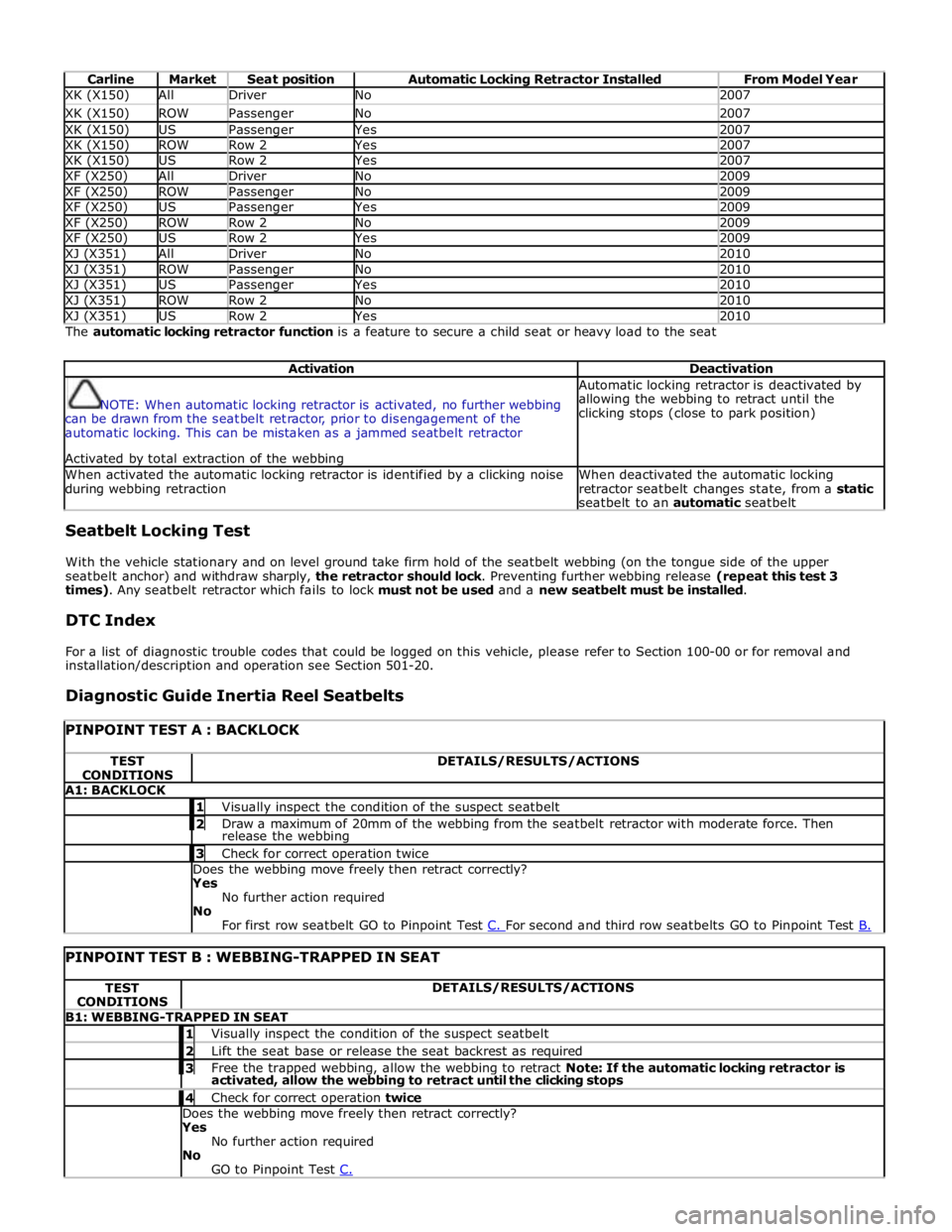
Carline Market Seat position Automatic Locking Retractor Installed From Model Year XK (X150) All Driver No 2007 XK (X150) ROW Passenger No 2007 XK (X150) US Passenger Yes 2007 XK (X150) ROW Row 2 Yes 2007 XK (X150) US Row 2 Yes 2007 XF (X250) All Driver No 2009 XF (X250) ROW Passenger No 2009 XF (X250) US Passenger Yes 2009 XF (X250) ROW Row 2 No 2009 XF (X250) US Row 2 Yes 2009 XJ (X351) All Driver No 2010 XJ (X351) ROW Passenger No 2010 XJ (X351) US Passenger Yes 2010 XJ (X351) ROW Row 2 No 2010 XJ (X351) US Row 2 Yes 2010 The automatic locking retractor function is a feature to secure a child seat or heavy load to the seat
Activation Deactivation
NOTE: When automatic locking retractor is activated, no further webbing
can be drawn from the seatbelt retractor, prior to disengagement of the
automatic locking. This can be mistaken as a jammed seatbelt retractor
Activated by total extraction of the webbing Automatic locking retractor is deactivated by
allowing the webbing to retract until the
clicking stops (close to park position) When activated the automatic locking retractor is identified by a clicking noise
during webbing retraction When deactivated the automatic locking
retractor seatbelt changes state, from a static
seatbelt to an automatic seatbelt Seatbelt Locking Test
With the vehicle stationary and on level ground take firm hold of the seatbelt webbing (on the tongue side of the upper
seatbelt anchor) and withdraw sharply, the retractor should lock. Preventing further webbing release (repeat this test 3
times). Any seatbelt retractor which fails to lock must not be used and a new seatbelt must be installed.
DTC Index
For a list of diagnostic trouble codes that could be logged on this vehicle, please refer to Section 100-00 or for removal and
installation/description and operation see Section 501-20.
Diagnostic Guide Inertia Reel Seatbelts
PINPOINT TEST A : BACKLOCK TEST
CONDITIONS DETAILS/RESULTS/ACTIONS A1: BACKLOCK 1 Visually inspect the condition of the suspect seatbelt 2 Draw a maximum of 20mm of the webbing from the seatbelt retractor with moderate force. Then release the webbing 3 Check for correct operation twice Does the webbing move freely then retract correctly?
Yes
No further action required
No
For first row seatbelt GO to Pinpoint Test C. For second and third row seatbelts GO to Pinpoint Test B.
PINPOINT TEST B : WEBBING-TRAPPED IN SEAT TEST
CONDITIONS DETAILS/RESULTS/ACTIONS B1: WEBBING-TRAPPED IN SEAT 1 Visually inspect the condition of the suspect seatbelt 2 Lift the seat base or release the seat backrest as required 3 Free the trapped webbing, allow the webbing to retract Note: If the automatic locking retractor is activated, allow the webbing to retract until the clicking stops 4 Check for correct operation twice Does the webbing move freely then retract correctly?
Yes
No further action required
No
GO to Pinpoint Test C.
Page 2614 of 3039
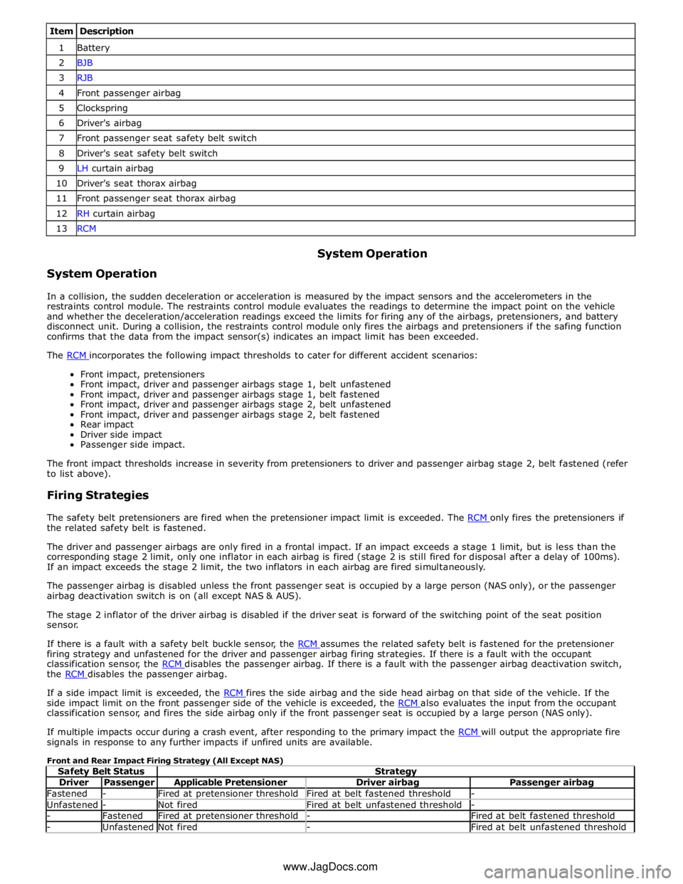
Item Description 1 Battery 2 BJB 3 RJB 4 Front passenger airbag 5 Clockspring 6 Driver's airbag 7 Front passenger seat safety belt switch 8 Driver's seat safety belt switch 9 LH curtain airbag 10 Driver's seat thorax airbag 11 Front passenger seat thorax airbag 12 RH curtain airbag 13 RCM
System Operation System Operation
In a collision, the sudden deceleration or acceleration is measured by the impact sensors and the accelerometers in the
restraints control module. The restraints control module evaluates the readings to determine the impact point on the vehicle
and whether the deceleration/acceleration readings exceed the limits for firing any of the airbags, pretensioners, and battery
disconnect unit. During a collision, the restraints control module only fires the airbags and pretensioners if the safing function
confirms that the data from the impact sensor(s) indicates an impact limit has been exceeded.
The RCM incorporates the following impact thresholds to cater for different accident scenarios: Front impact, pretensioners
Front impact, driver and passenger airbags stage 1, belt unfastened
Front impact, driver and passenger airbags stage 1, belt fastened
Front impact, driver and passenger airbags stage 2, belt unfastened
Front impact, driver and passenger airbags stage 2, belt fastened
Rear impact
Driver side impact
Passenger side impact.
The front impact thresholds increase in severity from pretensioners to driver and passenger airbag stage 2, belt fastened (refer
to list above).
Firing Strategies
The safety belt pretensioners are fired when the pretensioner impact limit is exceeded. The RCM only fires the pretensioners if the related safety belt is fastened.
The driver and passenger airbags are only fired in a frontal impact. If an impact exceeds a stage 1 limit, but is less than the
corresponding stage 2 limit, only one inflator in each airbag is fired (stage 2 is still fired for disposal after a delay of 100ms).
If an impact exceeds the stage 2 limit, the two inflators in each airbag are fired simultaneously.
The passenger airbag is disabled unless the front passenger seat is occupied by a large person (NAS only), or the passenger
airbag deactivation switch is on (all except NAS & AUS).
The stage 2 inflator of the driver airbag is disabled if the driver seat is forward of the switching point of the seat position
sensor.
If there is a fault with a safety belt buckle sensor, the RCM assumes the related safety belt is fastened for the pretensioner firing strategy and unfastened for the driver and passenger airbag firing strategies. If there is a fault with the occupant
classification sensor, the RCM disables the passenger airbag. If there is a fault with the passenger airbag deactivation switch, the RCM disables the passenger airbag.
If a side impact limit is exceeded, the RCM fires the side airbag and the side head airbag on that side of the vehicle. If the side impact limit on the front passenger side of the vehicle is exceeded, the RCM also evaluates the input from the occupant classification sensor, and fires the side airbag only if the front passenger seat is occupied by a large person (NAS only).
If multiple impacts occur during a crash event, after responding to the primary impact the RCM will output the appropriate fire signals in response to any further impacts if unfired units are available.
Front and Rear Impact Firing Strategy (All Except NAS)
Safety Belt Status Strategy Driver Passenger Applicable Pretensioner Driver airbag Passenger airbag Fastened - Fired at pretensioner threshold Fired at belt fastened threshold - Unfastened - Not fired Fired at belt unfastened threshold - - Fastened Fired at pretensioner threshold - Fired at belt fastened threshold - Unfastened Not fired - Fired at belt unfastened threshold www.JagDocs.com
Page 2624 of 3039
Published: 10-Jul-2014
Supplemental Restraint System - Air Bag and Safety Belt Pretensioner
Supplemental Restraint System (SRS)
Diagnosis and Testing
Principle of Operation
For a detailed description of the supplemental restraints system and operation, refer to the relevant Description and Operation
section in the workshop manual. REFER to: (501-20B Supplemental Restraint System)
Air Bag and Safety Belt Pretensioner Supplemental Restraint System (SRS) (Description and Operation), Air Bag and Safety Belt Pretensioner Supplemental Restraint System (SRS) (Description and Operation), Air Bag and Safety Belt Pretensioner Supplemental Restraint System (SRS) (Description and Operation).
Inspection and Verification
WARNING: TO AVOID ACCIDENTAL DEPLOYMENT AND POSSIBLE PERSONAL INJURY, THE BACKUP POWER SUPPLY MUST
BE DEPLETED BEFORE REPAIRING OR REPLACING ANY AIR BAG SUPPLEMENTAL RESTRAINT SYSTEM (SRS) COMPONENTS. TO
DEPLETE THE BACKUP POWER SUPPLY ENERGY, DISCONNECT THE BATTERY GROUND CABLE AND WAIT ONE MINUTE. FAILURE
TO FOLLOW THIS INSTRUCTION MAY RESULT IN PERSONAL INJURY.
CAUTION: Diagnosis by substitution from a donor vehicle is NOT acceptable. Substitution of control modules does not
guarantee confirmation of a fault, and may also cause additional faults in the vehicle being tested and/or the donor vehicle.
NOTE: Given the legal implications of a restraints system failure, harness repairs to Air Bag module circuits are not
acceptable. Where the text refers to "REPAIR the circuit", this will normally mean the replacement of a harness.
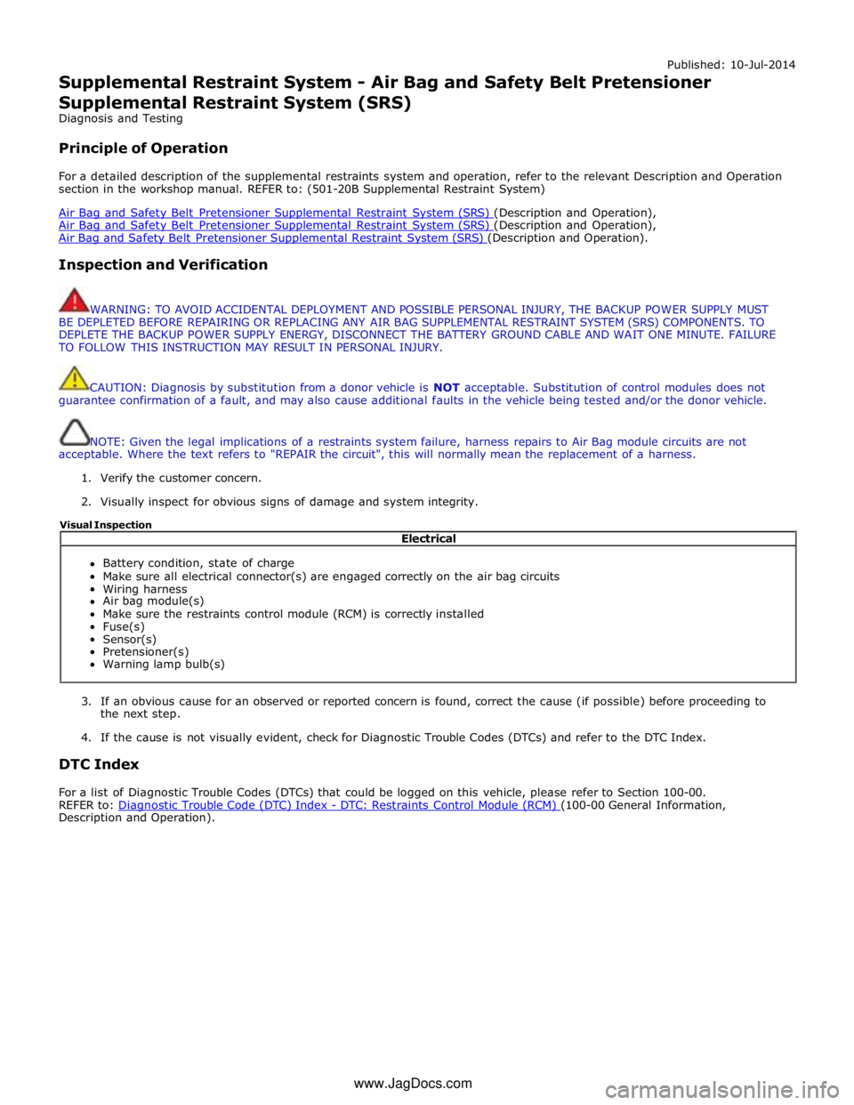
1. Verify the customer concern.
2. Visually inspect for obvious signs of damage and system integrity.
3. If an obvious cause for an observed or reported concern is found, correct the cause (if possible) before proceeding to
the next step.
4. If the cause is not visually evident, check for Diagnostic Trouble Codes (DTCs) and refer to the DTC Index.
DTC Index
For a list of Diagnostic Trouble Codes (DTCs) that could be logged on this vehicle, please refer to Section 100-00.
REFER to: Diagnostic Trouble Code (DTC) Index - DTC: Restraints Control Module (RCM) (100-00 General Information, Description and Operation). Electrical
Battery condition, state of charge
Make sure all electrical connector(s) are engaged correctly on the air bag circuits
Wiring harness
Air bag module(s)
Make sure the restraints control module (RCM) is correctly installed
Fuse(s)
Sensor(s)
Pretensioner(s)
Warning lamp bulb(s) Visual Inspection
www.JagDocs.com
Page 2625 of 3039
Supplemental Restraint System - Air Bag Disposal
General Procedures
Deployed Air Bag Published: 11-May-2011
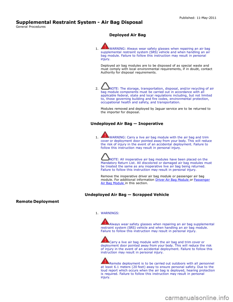
1. WARNING: Always wear safety glasses when repairing an air bag
supplemental restraint system (SRS) vehicle and when handling an air
bag module. Failure to follow this instruction may result in personal
injury.
Deployed air bag modules are to be disposed of as special waste and
must comply with local environmental requirements, if in doubt, contact
Authority for disposal requirements.
2. NOTE: The storage, transportation, disposal, and/or recycling of air
bag module components must be carried out in accordance with all
applicable federal, state and local regulations including, but not limited
to, those governing building and fire codes, environmental protection,
occupational health and safety, and transportation.
Modules removed and deployed by Jaguar service are to be returned to
the importer for disposal.
Undeployed Air Bag — Inoperative
1. WARNING: Carry a live air bag module with the air bag and trim
cover or deployment door pointed away from your body. This will reduce
the risk of injury in the event of an accidental deployment. Failure to
follow this instruction may result in personal injury.
NOTE: All inoperative air bag modules have been placed on the
Mandatory Return List. All discolored or damaged air bag modules must
be treated the same as any inoperative live air bag being returned.
Failure to follow this instruction may result in personal injury.
Remove the inoperative driver air bag module or passenger air bag
module. For additional information Driver Air Bag Module or Passenger Air Bag Module in this section.
Remote Deployment Undeployed Air Bag — Scrapped Vehicle
1. WARNINGS:
Always wear safety glasses when repairing an air bag supplemental
restraint system (SRS) vehicle and when handling an air bag module.
Failure to follow this instruction may result in personal injury.
Carry a live air bag module with the air bag and trim cover or
deployment door pointed away from your body. This will reduce the risk
of injury in the event of an accidental deployment. Failure to follow this
instruction may result in personal injury.
Remote deployment is to be carried out outdoors with all personnel
at least 6.1 meters (20 feet) away to ensure personal safety. Due to the
loud report which occurs when the air bag is deployed, hearing protection
is required. Failure to follow this instruction may result in personal
injury.
Page 2688 of 3039
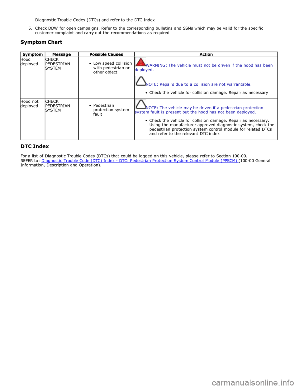
Diagnostic Trouble Codes (DTCs) and refer to the DTC Index
5. Check DDW for open campaigns. Refer to the corresponding bulletins and SSMs which may be valid for the specific
customer complaint and carry out the recommendations as required
Symptom Chart
Symptom Message Possible Causes Action Hood
deployed CHECK
PEDESTRIAN
SYSTEM
Low speed collision
with pedestrian or
other object
WARNING: The vehicle must not be driven if the hood has been
deployed.
NOTE: Repairs due to a collision are not warrantable.
Check the vehicle for collision damage. Repair as necessary Hood not
deployed CHECK
PEDESTRIAN
SYSTEM
Pedestrian
protection system
fault
NOTE: The vehicle may be driven if a pedestrian protection
system fault is present but the hood has not been deployed.
Check the vehicle for collision damage. Repair as necessary.
Using the manufacturer approved diagnostic system, check the
pedestrian protection system control module for related DTCs
and refer to the relevant DTC index
DTC Index
For a list of Diagnostic Trouble Codes (DTCs) that could be logged on this vehicle, please refer to Section 100-00.
REFER to: Diagnostic Trouble Code (DTC) Index - DTC: Pedestrian Protection System Control Module (PPSCM) (100-00 General Information, Description and Operation).
Page 2708 of 3039
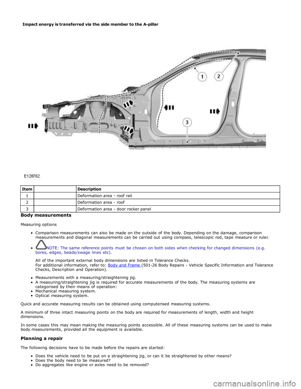
Item
Description 1
Deformation area - roof rail 2
Deformation area - roof 3
Deformation area - door rocker panel Body measurements
Measuring options
Comparison measurements can also be made on the outside of the body. Depending on the damage, comparison
measurements and diagonal measurements can be carried out using compass, telescopic rod, tape measure or ruler.
NOTE: The same reference points must be chosen on both sides when checking for changed dimensions (e.g.
bores, edges, beads/swage lines etc).
All of the important external body dimensions are listed in Tolerance Checks.
For additional information, refer to: Body and Frame (501-26 Body Repairs - Vehicle Specific Information and Tolerance Checks, Description and Operation).
Measurements with a measuring/straightening jig.
A measuring/straightening jig is required for accurate measurements of the body. The measuring systems are
categorised by their means of operation:
Mechanical measuring system.
Optical measuring system.
Quick and accurate measuring results can be obtained using computerised measuring systems.
A minimum of three intact measuring points on the body are required for measurements of length, width and height
dimensions.
In some cases this may mean making the measuring points accessible. All of these measuring systems can be used to make
body measurements, provided all the equipment is available.
Planning a repair
The following decisions have to be made before the repairs are started:
Does the vehicle need to be put on a straightening jig, or can it be straightened by other means?
Does the body need to be measured?
Do aggregates like engine or axles need to be removed? Impact energy is transferred via the side member to the A-pillar