2010 JAGUAR XFR list
[x] Cancel search: listPage 1372 of 3039
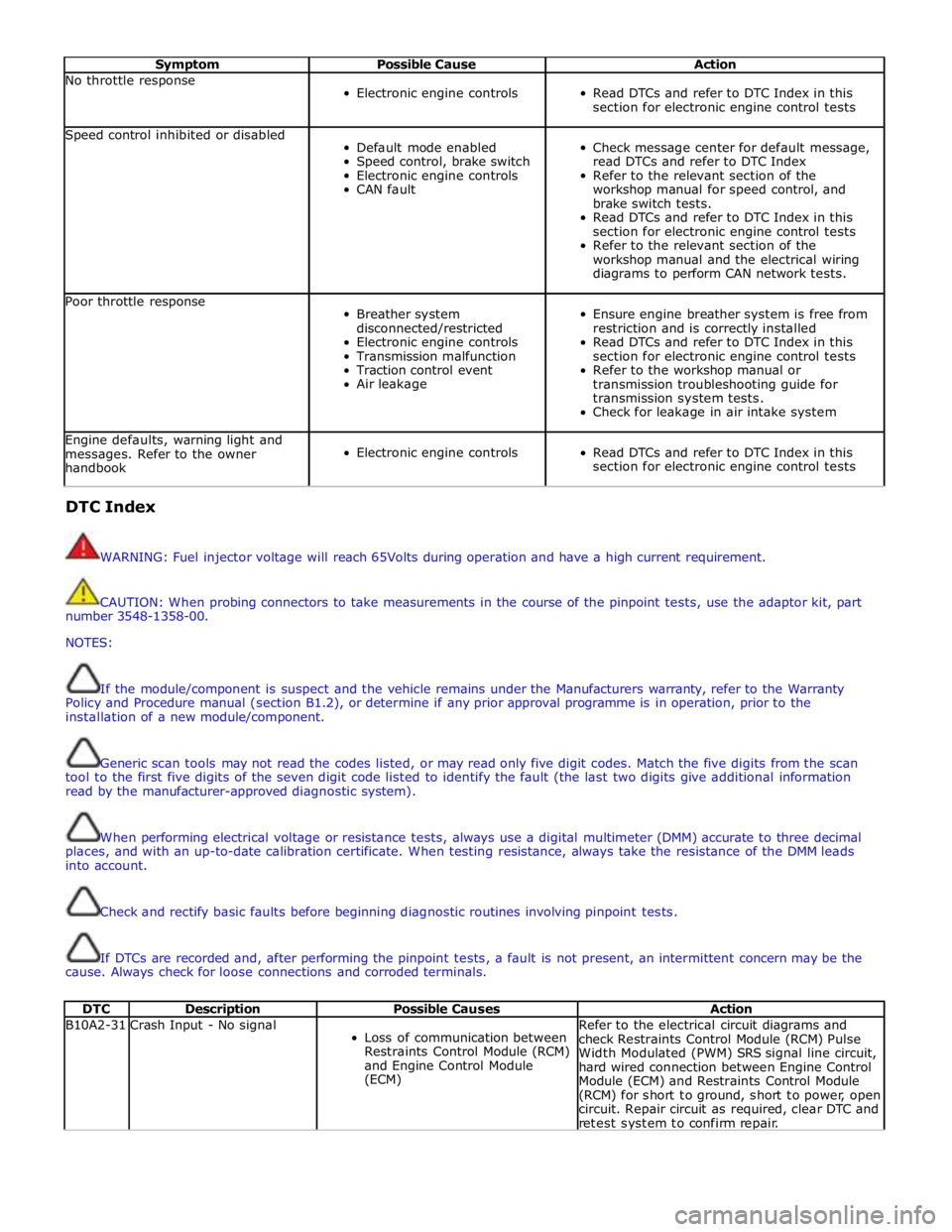
Symptom Possible Cause Action No throttle response
Electronic engine controls
Read DTCs and refer to DTC Index in this
section for electronic engine control tests Speed control inhibited or disabled
Default mode enabled
Speed control, brake switch
Electronic engine controls
CAN fault
Check message center for default message,
read DTCs and refer to DTC Index
Refer to the relevant section of the
workshop manual for speed control, and
brake switch tests.
Read DTCs and refer to DTC Index in this
section for electronic engine control tests
Refer to the relevant section of the
workshop manual and the electrical wiring
diagrams to perform CAN network tests. Poor throttle response
Breather system
disconnected/restricted
Electronic engine controls
Transmission malfunction
Traction control event
Air leakage
Ensure engine breather system is free from
restriction and is correctly installed
Read DTCs and refer to DTC Index in this
section for electronic engine control tests
Refer to the workshop manual or
transmission troubleshooting guide for
transmission system tests.
Check for leakage in air intake system Engine defaults, warning light and
messages. Refer to the owner
handbook
Electronic engine controls
Read DTCs and refer to DTC Index in this
section for electronic engine control tests DTC Index
WARNING: Fuel injector voltage will reach 65Volts during operation and have a high current requirement.
CAUTION: When probing connectors to take measurements in the course of the pinpoint tests, use the adaptor kit, part
number 3548-1358-00.
NOTES:
If the module/component is suspect and the vehicle remains under the Manufacturers warranty, refer to the Warranty
Policy and Procedure manual (section B1.2), or determine if any prior approval programme is in operation, prior to the
installation of a new module/component.
Generic scan tools may not read the codes listed, or may read only five digit codes. Match the five digits from the scan
tool to the first five digits of the seven digit code listed to identify the fault (the last two digits give additional information
read by the manufacturer-approved diagnostic system).
When performing electrical voltage or resistance tests, always use a digital multimeter (DMM) accurate to three decimal
places, and with an up-to-date calibration certificate. When testing resistance, always take the resistance of the DMM leads
into account.
Check and rectify basic faults before beginning diagnostic routines involving pinpoint tests.
If DTCs are recorded and, after performing the pinpoint tests, a fault is not present, an intermittent concern may be the
cause. Always check for loose connections and corroded terminals.
DTC Description Possible Causes Action B10A2-31 Crash Input - No signal
Loss of communication between
Restraints Control Module (RCM)
and Engine Control Module
(ECM) Refer to the electrical circuit diagrams and
check Restraints Control Module (RCM) Pulse
Width Modulated (PWM) SRS signal line circuit,
hard wired connection between Engine Control
Module (ECM) and Restraints Control Module
(RCM) for short to ground, short to power, open
circuit. Repair circuit as required, clear DTC and
retest system to confirm repair.
Page 1436 of 3039
Visual Inspection
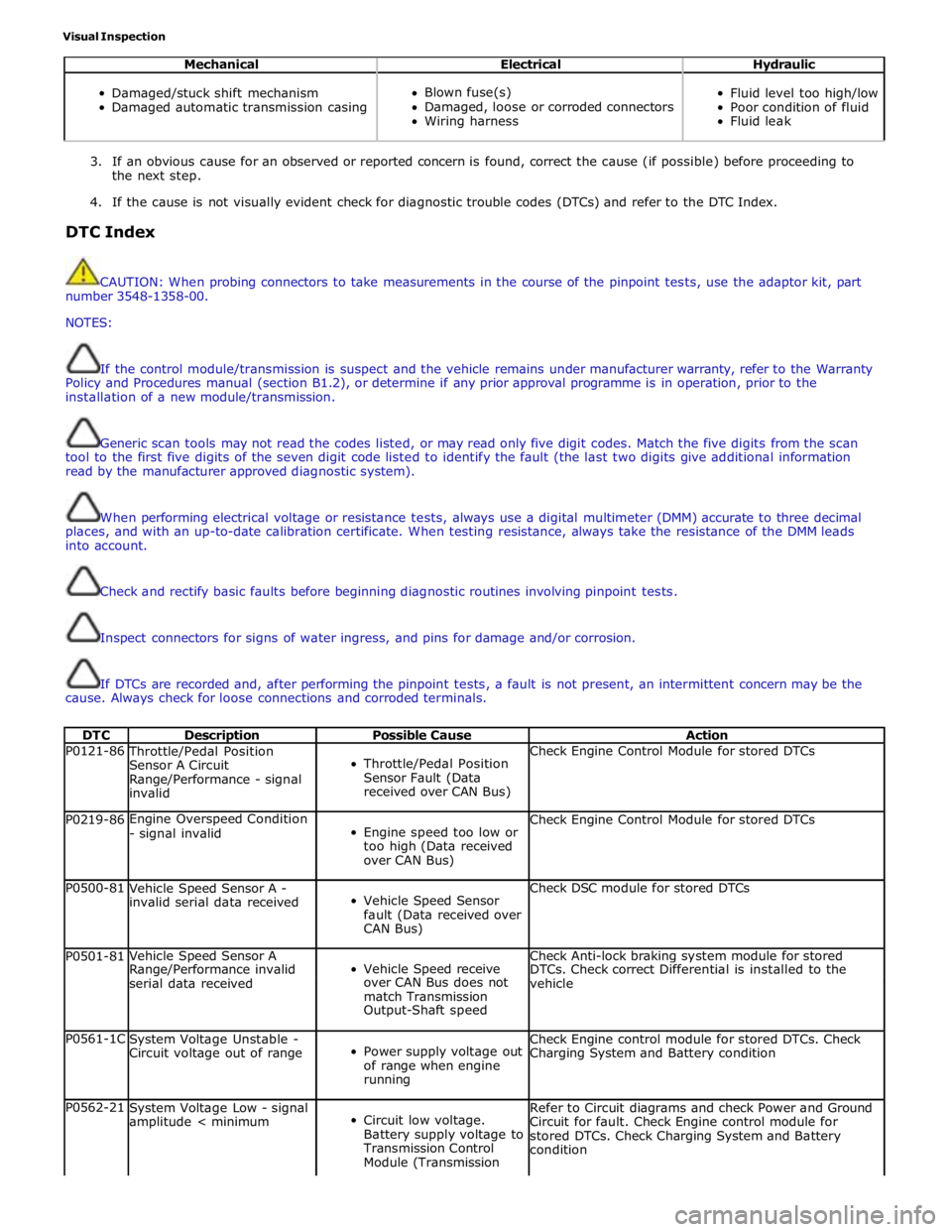
Mechanical Electrical Hydraulic
Damaged/stuck shift mechanism
Damaged automatic transmission casing
Blown fuse(s)
Damaged, loose or corroded connectors
Wiring harness
Fluid level too high/low
Poor condition of fluid
Fluid leak
3. If an obvious cause for an observed or reported concern is found, correct the cause (if possible) before proceeding to
the next step.
4. If the cause is not visually evident check for diagnostic trouble codes (DTCs) and refer to the DTC Index.
DTC Index
CAUTION: When probing connectors to take measurements in the course of the pinpoint tests, use the adaptor kit, part
number 3548-1358-00.
NOTES:
If the control module/transmission is suspect and the vehicle remains under manufacturer warranty, refer to the Warranty
Policy and Procedures manual (section B1.2), or determine if any prior approval programme is in operation, prior to the
installation of a new module/transmission.
Generic scan tools may not read the codes listed, or may read only five digit codes. Match the five digits from the scan
tool to the first five digits of the seven digit code listed to identify the fault (the last two digits give additional information
read by the manufacturer approved diagnostic system).
When performing electrical voltage or resistance tests, always use a digital multimeter (DMM) accurate to three decimal
places, and with an up-to-date calibration certificate. When testing resistance, always take the resistance of the DMM leads
into account.
Check and rectify basic faults before beginning diagnostic routines involving pinpoint tests.
Inspect connectors for signs of water ingress, and pins for damage and/or corrosion.
If DTCs are recorded and, after performing the pinpoint tests, a fault is not present, an intermittent concern may be the
cause. Always check for loose connections and corroded terminals.
DTC Description Possible Cause Action P0121-86 Throttle/Pedal Position
Sensor A Circuit
Range/Performance - signal
invalid
Throttle/Pedal Position
Sensor Fault (Data
received over CAN Bus) Check Engine Control Module for stored DTCs P0219-86 Engine Overspeed Condition
- signal invalid
Engine speed too low or
too high (Data received
over CAN Bus) Check Engine Control Module for stored DTCs P0500-81
Vehicle Speed Sensor A -
invalid serial data received
Vehicle Speed Sensor
fault (Data received over
CAN Bus) Check DSC module for stored DTCs P0501-81 Vehicle Speed Sensor A
Vehicle Speed receive Check Anti-lock braking system module for stored Range/Performance invalid DTCs. Check correct Differential is installed to the serial data received over CAN Bus does not
vehicle match Transmission Output-Shaft speed P0561-1C
System Voltage Unstable -
Circuit voltage out of range
Power supply voltage out
of range when engine
running Check Engine control module for stored DTCs. Check
Charging System and Battery condition P0562-21
System Voltage Low - signal
amplitude < minimum
Circuit low voltage.
Battery supply voltage to
Transmission Control
Module (Transmission Refer to Circuit diagrams and check Power and Ground
Circuit for fault. Check Engine control module for
stored DTCs. Check Charging System and Battery
condition
Page 1534 of 3039

Published: 19-Jun-2013
Automatic Transmission/Transaxle External Controls - TDV6 3.0L Diesel /V8 5.0L Petrol/V8 S/C 5.0L Petrol - External Controls
Diagnosis and Testing
Principles of Operation
For a detailed description of the transmission external controls, refer to the relevant Description and Operation sections in the
workshop manual. REFER to: (307-05)
External Controls (Description and Operation),
External Controls (Description and Operation),
External Controls (Description and Operation).
Inspection and Verification
CAUTION: Diagnosis by substitution from a donor vehicle is NOT acceptable. Substitution of control modules does not
guarantee confirmation of a fault, and may also cause additional faults in the vehicle being tested and/or the donor vehicle.
1. Verify the customer concern.
2. Visually inspect for obvious signs of damage and system integrity.
Visual Inspection
Mechanical Electrical
Check for stuck/jammed switches and buttons
Visibly damaged or worn components
Loose or missing fasteners
Fuse(s)
Loose or corroded electrical connector(s)
Transmission control module
Transmission control switch
3. If an obvious cause for an observed or reported concern is found, correct the cause (if possible) before proceeding to
the next step.
4. If the cause is not visually evident, check for Diagnostic Trouble Codes (DTCs) and refer to the DTC Index.
DTC Index
For a list of DTCs that could be logged on this vehicle, please refer to Section 100-00.
REFER to: Diagnostic Trouble Code (DTC) Index - DTC: Transmission Control Module (TCM) (100-00, Description and Operation)
/
Diagnostic Trouble Code (DTC) Index - DTC: Transmission Control Switch (TCS) (100-00, Description and Operation).
Page 1549 of 3039

Published: 11-May-2011
Exhaust System - V8 5.0L Petrol/V8 S/C 5.0L Petrol - Exhaust System
Diagnosis and Testing
Principle of Operation
For a detailed description of the exhaust system, refer to the relevant Description and Operation section of the workshop
manual. REFER to: (309-00C Exhaust System - V8 5.0L Petrol/V8 S/C 5.0L Petrol)
Exhaust System (Description and Operation), Exhaust System (Description and Operation), Exhaust System (Description and Operation).
Inspection and Verification
CAUTION: Diagnosis by substitution from a donor vehicle is NOT acceptable. Substitution of control modules does not
guarantee confirmation of a fault and may also cause additional faults in the vehicle being checked and/or the donor vehicle.
NOTE: Check and rectify basic faults before beginning diagnostic routines involving pinpoint tests.
1. Verify the customer concern.
2. Visually inspect for obvious signs of damage and system integrity.
3. If an obvious cause for an observed or reported concern is found, correct the cause (if possible) before proceeding to
the next step.
4. If the cause is not visually evident, verify the symptom and refer to the Symptom Chart, alternatively check for
Diagnostic Trouble Codes (DTCs) and refer to the DTC Index.
Symptom Chart
Symptom Possible Causes Action Excessively
noisy/leaking
exhaust
Exhaust
system/components Inspect exhaust system. Rectify leaks and install new components as
required. Refer to Removal and Installation instructions in this section Loss of power
Restricted exhaust system
Exhaust sound
enhancement valve stuck
closed
Fuel system
Ignition system
Electronic engine control Inspect exhaust system. Install new exhaust components as required.
Refer to Removal and Installation instructions in this section. Check for
fuel, ignition and electronic engine control system DTCs and refer to the
relevant DTC Index
DTC Index
For a list of Diagnostic Trouble Codes (DTCs) that could be logged in the Engine Control Module (ECM), please refer to Section
303-14. REFER to:
Electronic Engine Controls (303-14C Electronic Engine Controls - V8 5.0L Petrol, Diagnosis and Testing), Electronic Engine Controls (303-14D Electronic Engine Controls - V8 S/C 5.0L Petrol, Diagnosis and Testing). Mechanical
Leaks
Metal fatigue
Pipes
Catalytic converter
Muffler(s)
Joints
Mountings
Clearance around components Visual Inspection
Page 1598 of 3039

Resistance (Ω) CAN Count (Tolerance ± 10) Resistance (Ω) CAN Count (Tolerance ± 10) 6 86 119 51 74 8 121 160 51 74 10 151 191 51 74 Empty 12 183 223 51 74 14 205 244 51 74 16 242 276 51 74 18 283 308 51 74 20 327 340 51 74 ¼ 22 358 361 51 74 24 408 392 51 74 26 445 414 51 74 28 446 436 51 74 30 446 436 51 74 32 446 436 59 85 34 446 436 75 106 36 445 425 101 148 38 486 436 170 159 40 486 446 140 170 ½ 42 486 446 160 201 44 460 425 192 223 46 486 446 204 243 48 552 457 204 243 50 626 489 204 243 52 654 521 228 254 54 654 521 241 275 56 654 521 254 286 ¾ 58 654 521 281 307 60 684 531 296 318 62 707 531 326 339 64 727 541 357 350 66 737 562 373 370 Full 67 803 563 407 391 Maximum Fill Maximum Fill 911 594 425 402 DTC Index
For a list of Diagnostic Trouble Codes (DTCs) that could be logged in the Engine Control Module (ECM), please refer to Section
303-14. REFER to:
Electronic Engine Controls (303-14C Electronic Engine Controls - V8 5.0L Petrol, Diagnosis and Testing), Electronic Engine Controls (303-14D Electronic Engine Controls - V8 S/C 5.0L Petrol, Diagnosis and Testing).
Page 1631 of 3039
Acceleration Control - Acceleration Control
Diagnosis and Testing
Principles of Operation Published: 11-May-2011
For a detailed description of the acceleration controls, refer to the relevant Description and Operation sections in the workshop
manual. REFER to: Acceleration Control (310-02, Description and Operation).
Inspection and Verification
CAUTION: Diagnosis by substitution from a donor vehicle is NOT acceptable. Substitution of control modules does not
guarantee confirmation of a fault, and may also cause additional faults in the vehicle being tested and/or the donor vehicle.
1. Verify the customer concern.
2. Visually inspect for obvious signs of damage and system integrity.
Visual Inspection
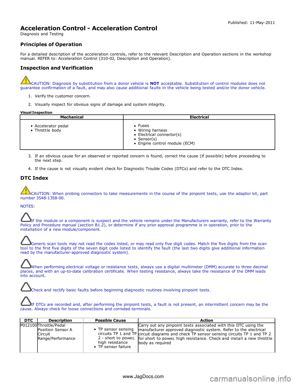
Mechanical Electrical
Accelerator pedal
Throttle body
Fuses
Wiring harness
Electrical connector(s)
Sensor(s)
Engine control module (ECM)
3. If an obvious cause for an observed or reported concern is found, correct the cause (if possible) before proceeding to
the next step.
4. If the cause is not visually evident check for Diagnostic Trouble Codes (DTCs) and refer to the DTC Index.
DTC Index
CAUTION: When probing connectors to take measurements in the course of the pinpoint tests, use the adaptor kit, part
number 3548-1358-00.
NOTES:
If the module or a component is suspect and the vehicle remains under the Manufacturers warranty, refer to the Warranty
Policy and Procedure manual (section B1.2), or determine if any prior approval programme is in operation, prior to the
installation of a new module/component.
Generic scan tools may not read the codes listed, or may read only five digit codes. Match the five digits from the scan
tool to the first five digits of the seven digit code listed to identify the fault (the last two digits give additional information
read by the manufacturer-approved diagnostic system).
When performing electrical voltage or resistance tests, always use a digital multimeter (DMM) accurate to three decimal
places, and with an up-to-date calibration certificate. When testing resistance, always take the resistance of the DMM leads
into account.
Check and rectify basic faults before beginning diagnostic routines involving pinpoint tests.
If DTCs are recorded and, after performing the pinpoint tests, a fault is not present, an intermittent concern may be the
cause. Always check for loose connections and corroded terminals.
DTC Description Possible Cause Action P012100 Throttle/Pedal
Position Sensor A
Circuit
Range/Performance
TP sensor sensing
circuits TP 1 and TP
2 - short to power,
high resistance
TP sensor failure Carry out any pinpoint tests associated with this DTC using the
manufacturer approved diagnostic system. Refer to the electrical
circuit diagrams and check TP sensor sensing circuits TP 1 and TP 2
for short to power, high resistance. Check and install a new throttle
body as required www.JagDocs.com
Page 1647 of 3039
DTC Index
Vehicles WITH Adaptive System Installed
CAUTION: When probing connectors to take measurements in the course of the pinpoint tests, use the adaptor kit, part
number 3548-1358-00
NOTES:
If a module or component is suspect, and the vehicle remains under the Manufacturers warranty, refer to the Warranty
Policy and Procedure manual (section B1.2), or determine if any prior approval programme is in operation, prior to the
installation of a new module/component.
Generic scan tools may not read the codes listed, or may read only five digit codes. Match the five digits from the scan
tool to the first five digits of the seven digit code listed to identify the fault (the last two digits give extra information read by
the manufacturer-approved diagnostic system).
When performing voltage or resistance tests, always use a digital multimeter (DMM) accurate to three decimal places and
with a current calibration certificate. When testing resistance, always take the resistance of the DMM leads into account.
Check and rectify basic faults before beginning diagnostic routines involving pinpoint tests.
If DTCs are recorded and, after performing the pinpoint tests, a fault is not present, an intermittent concern may be the
cause. Always check for loose connections and corroded terminals.
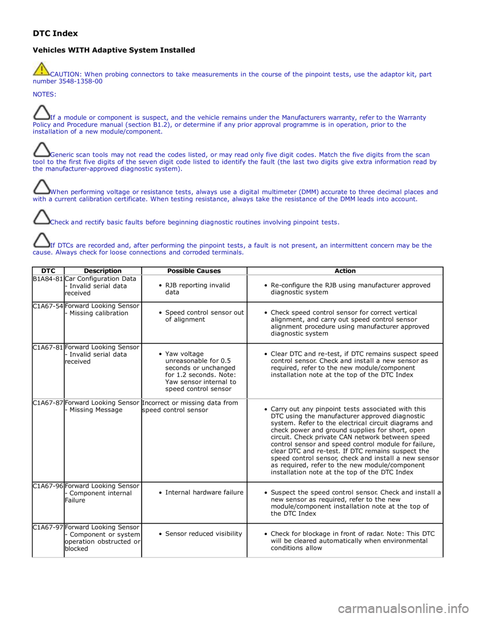
DTC Description Possible Causes Action B1A84-81 Car Configuration Data
- Invalid serial data
received
RJB reporting invalid
data
Re-configure the RJB using manufacturer approved
diagnostic system C1A67-54 Forward Looking Sensor
- Missing calibration
Speed control sensor out
of alignment
Check speed control sensor for correct vertical
alignment, and carry out speed control sensor
alignment procedure using manufacturer approved
diagnostic system C1A67-81 Forward Looking Sensor
- Invalid serial data
received
Yaw voltage
unreasonable for 0.5
seconds or unchanged
for 1.2 seconds. Note:
Yaw sensor internal to
speed control sensor
Clear DTC and re-test, if DTC remains suspect speed
control sensor. Check and install a new sensor as
required, refer to the new module/component
installation note at the top of the DTC Index C1A67-87 Forward Looking Sensor
- Missing Message Incorrect or missing data from
speed control sensor
Carry out any pinpoint tests associated with this
DTC using the manufacturer approved diagnostic
system. Refer to the electrical circuit diagrams and
check power and ground supplies for short, open
circuit. Check private CAN network between speed
control sensor and speed control module for failure,
clear DTC and re-test. If DTC remains suspect the
speed control sensor, check and install a new sensor
as required, refer to the new module/component
installation note at the top of the DTC Index C1A67-96 Forward Looking Sensor
- Component internal
Failure
Internal hardware failure
Suspect the speed control sensor. Check and install a
new sensor as required, refer to the new
module/component installation note at the top of
the DTC Index C1A67-97 Forward Looking Sensor
- Component or system
operation obstructed or
blocked
Sensor reduced visibility
Check for blockage in front of radar. Note: This DTC
will be cleared automatically when environmental
conditions allow
Page 1650 of 3039
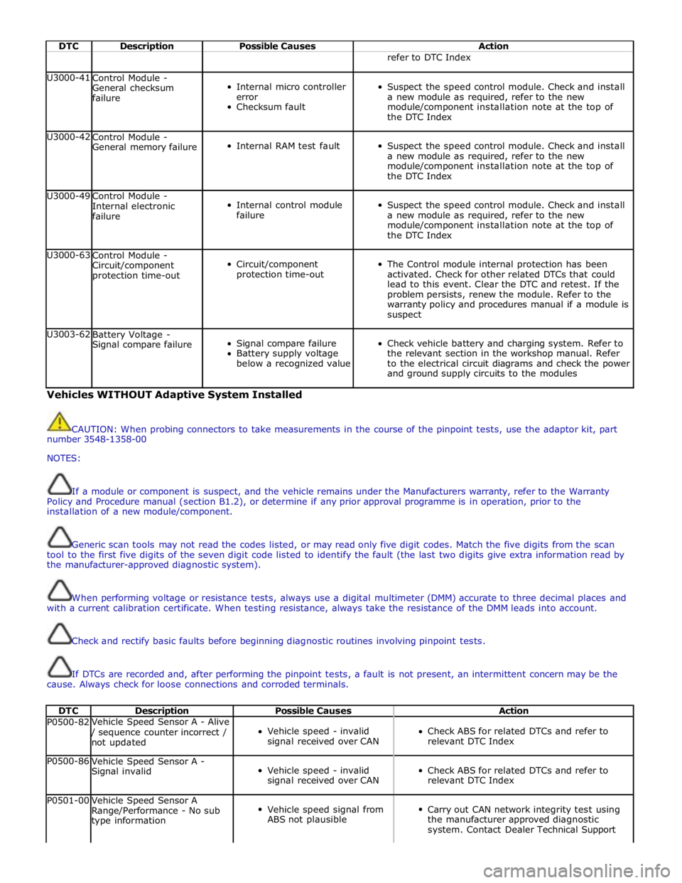
DTC Description Possible Causes Action refer to DTC Index U3000-41
Control Module -
General checksum
failure
Internal micro controller
error
Checksum fault
Suspect the speed control module. Check and install
a new module as required, refer to the new
module/component installation note at the top of
the DTC Index U3000-42
Control Module -
General memory failure
Internal RAM test fault
Suspect the speed control module. Check and install
a new module as required, refer to the new
module/component installation note at the top of
the DTC Index U3000-49
Control Module -
Internal electronic
failure
Internal control module
failure
Suspect the speed control module. Check and install
a new module as required, refer to the new
module/component installation note at the top of
the DTC Index U3000-63
Control Module -
Circuit/component
protection time-out
Circuit/component
protection time-out
The Control module internal protection has been
activated. Check for other related DTCs that could
lead to this event. Clear the DTC and retest. If the
problem persists, renew the module. Refer to the
warranty policy and procedures manual if a module is
suspect U3003-62
Battery Voltage -
Signal compare failure
Signal compare failure
Battery supply voltage
below a recognized value
Check vehicle battery and charging system. Refer to
the relevant section in the workshop manual. Refer
to the electrical circuit diagrams and check the power
and ground supply circuits to the modules Vehicles WITHOUT Adaptive System Installed
CAUTION: When probing connectors to take measurements in the course of the pinpoint tests, use the adaptor kit, part
number 3548-1358-00
NOTES:
If a module or component is suspect, and the vehicle remains under the Manufacturers warranty, refer to the Warranty
Policy and Procedure manual (section B1.2), or determine if any prior approval programme is in operation, prior to the
installation of a new module/component.
Generic scan tools may not read the codes listed, or may read only five digit codes. Match the five digits from the scan
tool to the first five digits of the seven digit code listed to identify the fault (the last two digits give extra information read by
the manufacturer-approved diagnostic system).
When performing voltage or resistance tests, always use a digital multimeter (DMM) accurate to three decimal places and
with a current calibration certificate. When testing resistance, always take the resistance of the DMM leads into account.
Check and rectify basic faults before beginning diagnostic routines involving pinpoint tests.
If DTCs are recorded and, after performing the pinpoint tests, a fault is not present, an intermittent concern may be the
cause. Always check for loose connections and corroded terminals.
DTC Description Possible Causes Action P0500-82 Vehicle Speed Sensor A - Alive / sequence counter incorrect /
not updated
Vehicle speed - invalid
signal received over CAN
Check ABS for related DTCs and refer to
relevant DTC Index P0500-86
Vehicle Speed Sensor A -
Signal invalid
Vehicle speed - invalid
signal received over CAN
Check ABS for related DTCs and refer to
relevant DTC Index P0501-00
Vehicle Speed Sensor A
Range/Performance - No sub
type information
Vehicle speed signal from
ABS not plausible
Carry out CAN network integrity test using
the manufacturer approved diagnostic
system. Contact Dealer Technical Support