2010 JAGUAR XFR list
[x] Cancel search: listPage 1667 of 3039
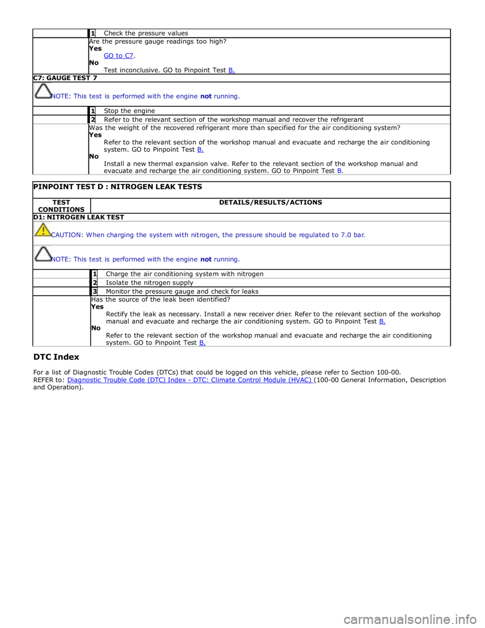
1 Check the pressure values Are the pressure gauge readings too high? Yes
GO to C7. No
Test inconclusive. GO to Pinpoint Test B. C7: GAUGE TEST 7
NOTE: This test is performed with the engine not running. 1 Stop the engine 2 Refer to the relevant section of the workshop manual and recover the refrigerant Was the weight of the recovered refrigerant more than specified for the air conditioning system? Yes
Refer to the relevant section of the workshop manual and evacuate and recharge the air conditioning
system. GO to Pinpoint Test B. No
Install a new thermal expansion valve. Refer to the relevant section of the workshop manual and
evacuate and recharge the air conditioning system. GO to Pinpoint Test B.
PINPOINT TEST D : NITROGEN LEAK TESTS TEST
CONDITIONS DETAILS/RESULTS/ACTIONS D1: NITROGEN LEAK TEST
CAUTION: When charging the system with nitrogen, the pressure should be regulated to 7.0 bar.
NOTE: This test is performed with the engine not running. 1 Charge the air conditioning system with nitrogen 2 Isolate the nitrogen supply 3 Monitor the pressure gauge and check for leaks Has the source of the leak been identified?
Yes
Rectify the leak as necessary. Install a new receiver drier. Refer to the relevant section of the workshop
manual and evacuate and recharge the air conditioning system. GO to Pinpoint Test B. No
Refer to the relevant section of the workshop manual and evacuate and recharge the air conditioning system. GO to Pinpoint Test B.
DTC Index
For a list of Diagnostic Trouble Codes (DTCs) that could be logged on this vehicle, please refer to Section 100-00.
REFER to: Diagnostic Trouble Code (DTC) Index - DTC: Climate Control Module (HVAC) (100-00 General Information, Description and Operation).
Page 1797 of 3039
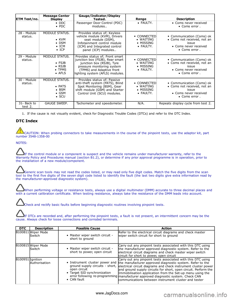
ETM Test/no. Message Center Display Gauge/Indicator/Display
Tested.
Range
Description DDC
PDC Passenger Door Control (PDC)
modules.. FAULTY.
Coms never received
Coms error . 28 - Module MODULE STATUS. Provides status of; Keyless
CONNECTED
Communication (Coms) ok status. vehicle module (KVM), Drivers KVM
seat module (DSM), WAITING Coms not received, not an DSM
Infotainment control module MISSING issue ICM
(ICM) and Integrated control FAULTY. Coms never received ICP
panel (ICP) modules.. Coms error . 29 - Module MODULE STATUS. Provides status of; Front smart
CONNECTED
Communication (Coms) ok status. junction box (FSJB), Rear smart FSJB
junction box (RSJB), Tyre WAITING Coms not received, not an RSJB
pressure monitoring system MISSING issue TPMS
(TPMS) and Adaptive front FAULTY. Coms never received AFLS
lighting system (AFLS) modules. Coms error . 30 - Module MODULE STATUS. Provides status of; Passive
CONNECTED
Communication (Coms) ok status. anti-theft system (PATS), Blind PATS
Spot Monitoring (BSM), Gear WAITING Coms not received, not an BSM
shift module (GSM) and Starter MISSING issue GSM
Control Unit (SCU) modules. FAULTY. Coms never received SCU Coms error . 31- Back to
test 2. GAUGE SWEEP. Tachometer and speedometer. N/A. Repeats display cycle from test 2.
1. If the cause is not visually evident, check for Diagnostic Trouble Codes (DTCs) and refer to the DTC Index.
DTC Index
CAUTION: When probing connectors to take measurements in the course of the pinpoint tests, use the adaptor kit, part
number 3548-1358-00
NOTES:
If the control module or a component is suspect and the vehicle remains under manufacturer warranty, refer to the
Warranty Policy and Procedures manual (section B1.2), or determine if any prior approval programme is in operation, prior to
the installation of a new module/component.
Generic scan tools may not read the codes listed, or may read only five digit codes. Match the five digits from the scan
tool to the first five digits of the seven digit code listed to identify the fault (the last two digits give extra information read by
the manufacturer-approved diagnostic system).
When performing voltage or resistance tests, always use a digital multimeter (DMM) accurate to three decimal places and
with a current calibration certificate. When testing resistance, always take the resistance of the DMM leads into account.
Check and rectify basic faults before beginning diagnostic routines involving pinpoint tests.
If DTCs are recorded and, after performing the pinpoint tests, a fault is not present, an intermittent concern may be the
cause. Always check for loose connections and corroded terminals.
DTC Description Possible Cause Action B100811
Wiper Mode
Switch
Master wiper switch circuit -
short to ground Refer to the electrical circuit diagrams and check master
wiper switch circuit for short to ground B100815
Wiper Mode
Switch
Master wiper switch circuit -
short to power, open circuit Carry out any pinpoint tests associated with this DTC using
the manufacturer approved diagnostic system. Refer to the
electrical circuit diagrams and check master wiper switch
circuit for short to power, open circuit B100951
Ignition
Authorisation
Instrument cluster power and
ground supply circuits - short,
open circuit
Target SID synchronization
error following re-programming
CAN fault Carry out any pinpoint tests associated with this DTC using
the manufacturer approved diagnostic system. Refer to the
electrical circuit diagrams and check instrument cluster power
and ground supply circuits for short, open circuit. Perform the
Immobilisation application from the Set-up menu using the
manufacturer approved diagnostic system. Check CAN
communications between instrument cluster and tester www.JagDocs.com
Page 1826 of 3039
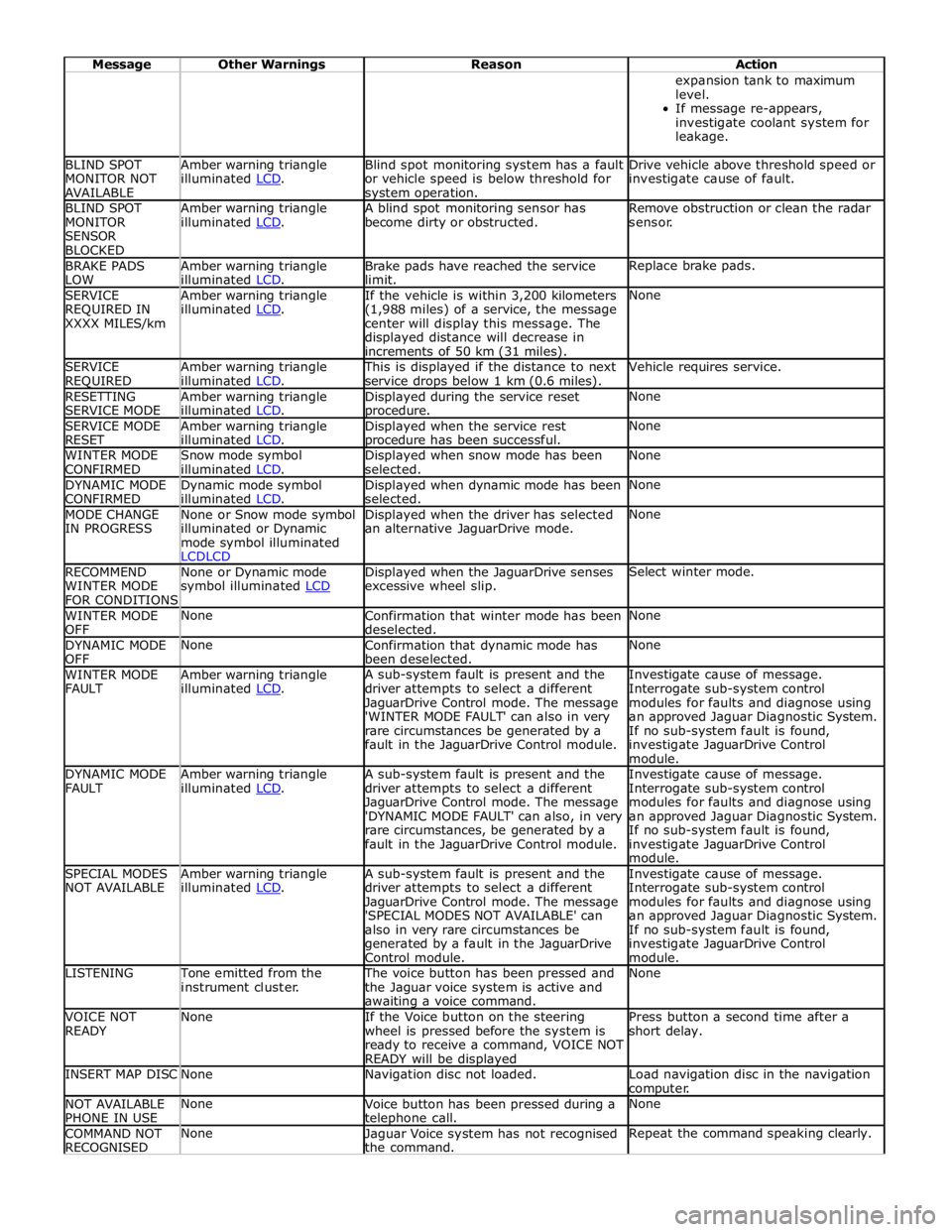
Message Other Warnings Reason Action expansion tank to maximum
level.
If message re-appears,
investigate coolant system for
leakage. BLIND SPOT
MONITOR NOT
AVAILABLE Amber warning triangle
illuminated LCD. Blind spot monitoring system has a fault
or vehicle speed is below threshold for system operation. Drive vehicle above threshold speed or
investigate cause of fault. BLIND SPOT
MONITOR
SENSOR
BLOCKED Amber warning triangle
illuminated LCD. A blind spot monitoring sensor has
become dirty or obstructed. Remove obstruction or clean the radar
sensor. BRAKE PADS
LOW Amber warning triangle
illuminated LCD. Brake pads have reached the service
limit. Replace brake pads. SERVICE
REQUIRED IN
XXXX MILES/km Amber warning triangle
illuminated LCD. If the vehicle is within 3,200 kilometers
(1,988 miles) of a service, the message
center will display this message. The
displayed distance will decrease in
increments of 50 km (31 miles). None SERVICE
REQUIRED Amber warning triangle
illuminated LCD. This is displayed if the distance to next
service drops below 1 km (0.6 miles). Vehicle requires service. RESETTING
SERVICE MODE Amber warning triangle
illuminated LCD. Displayed during the service reset procedure. None SERVICE MODE
RESET Amber warning triangle
illuminated LCD. Displayed when the service rest procedure has been successful. None WINTER MODE
CONFIRMED Snow mode symbol
illuminated LCD. Displayed when snow mode has been
selected. None DYNAMIC MODE
CONFIRMED Dynamic mode symbol
illuminated LCD. Displayed when dynamic mode has been
selected. None MODE CHANGE
IN PROGRESS None or Snow mode symbol
illuminated or Dynamic
mode symbol illuminated
LCDLCD Displayed when the driver has selected
an alternative JaguarDrive mode. None RECOMMEND
WINTER MODE
FOR CONDITIONS None or Dynamic mode
symbol illuminated LCD Displayed when the JaguarDrive senses
excessive wheel slip. Select winter mode. WINTER MODE
OFF None
Confirmation that winter mode has been
deselected. None DYNAMIC MODE
OFF None
Confirmation that dynamic mode has
been deselected. None WINTER MODE
FAULT Amber warning triangle
illuminated LCD. A sub-system fault is present and the
driver attempts to select a different
JaguarDrive Control mode. The message
'WINTER MODE FAULT' can also in very
rare circumstances be generated by a
fault in the JaguarDrive Control module. Investigate cause of message.
Interrogate sub-system control
modules for faults and diagnose using
an approved Jaguar Diagnostic System.
If no sub-system fault is found,
investigate JaguarDrive Control
module. DYNAMIC MODE
FAULT Amber warning triangle
illuminated LCD. A sub-system fault is present and the
driver attempts to select a different
JaguarDrive Control mode. The message
'DYNAMIC MODE FAULT' can also, in very
rare circumstances, be generated by a
fault in the JaguarDrive Control module. Investigate cause of message.
Interrogate sub-system control
modules for faults and diagnose using
an approved Jaguar Diagnostic System.
If no sub-system fault is found,
investigate JaguarDrive Control
module. SPECIAL MODES
NOT AVAILABLE Amber warning triangle
illuminated LCD. A sub-system fault is present and the
driver attempts to select a different
JaguarDrive Control mode. The message
'SPECIAL MODES NOT AVAILABLE' can
also in very rare circumstances be
generated by a fault in the JaguarDrive
Control module. Investigate cause of message.
Interrogate sub-system control
modules for faults and diagnose using
an approved Jaguar Diagnostic System.
If no sub-system fault is found,
investigate JaguarDrive Control
module. LISTENING Tone emitted from the
instrument cluster. The voice button has been pressed and
the Jaguar voice system is active and awaiting a voice command. None VOICE NOT
READY None
If the Voice button on the steering
wheel is pressed before the system is
ready to receive a command, VOICE NOT
READY will be displayed Press button a second time after a
short delay. INSERT MAP DISC None Navigation disc not loaded.
Load navigation disc in the navigation
computer. NOT AVAILABLE
PHONE IN USE None
Voice button has been pressed during a telephone call. None COMMAND NOT
RECOGNISED None
Jaguar Voice system has not recognised
the command. Repeat the command speaking clearly.
Page 1829 of 3039
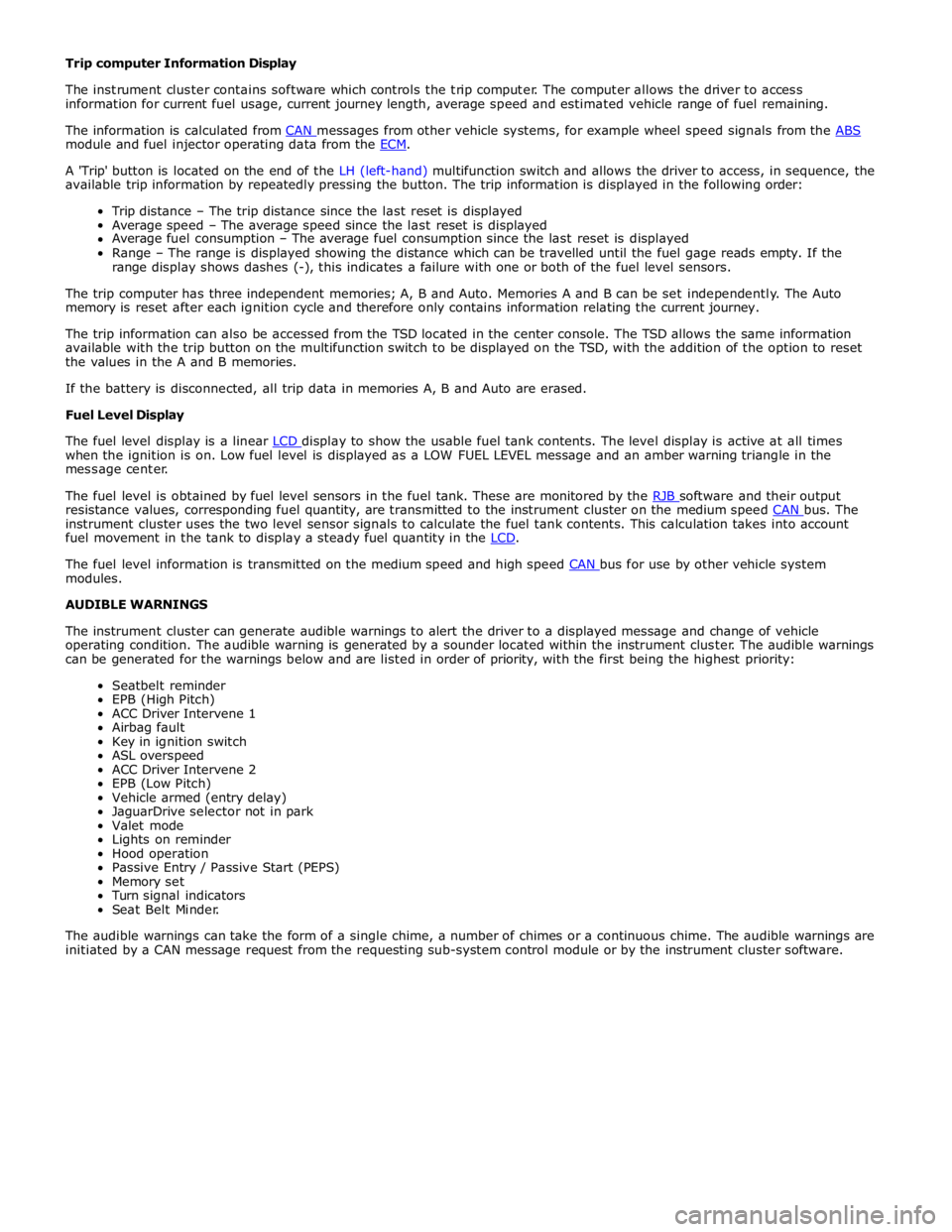
module and fuel injector operating data from the ECM.
A 'Trip' button is located on the end of the LH (left-hand) multifunction switch and allows the driver to access, in sequence, the
available trip information by repeatedly pressing the button. The trip information is displayed in the following order:
Trip distance – The trip distance since the last reset is displayed
Average speed – The average speed since the last reset is displayed
Average fuel consumption – The average fuel consumption since the last reset is displayed
Range – The range is displayed showing the distance which can be travelled until the fuel gage reads empty. If the
range display shows dashes (-), this indicates a failure with one or both of the fuel level sensors.
The trip computer has three independent memories; A, B and Auto. Memories A and B can be set independently. The Auto
memory is reset after each ignition cycle and therefore only contains information relating the current journey.
The trip information can also be accessed from the TSD located in the center console. The TSD allows the same information
available with the trip button on the multifunction switch to be displayed on the TSD, with the addition of the option to reset
the values in the A and B memories.
If the battery is disconnected, all trip data in memories A, B and Auto are erased.
Fuel Level Display
The fuel level display is a linear LCD display to show the usable fuel tank contents. The level display is active at all times when the ignition is on. Low fuel level is displayed as a LOW FUEL LEVEL message and an amber warning triangle in the
message center.
The fuel level is obtained by fuel level sensors in the fuel tank. These are monitored by the RJB software and their output resistance values, corresponding fuel quantity, are transmitted to the instrument cluster on the medium speed CAN bus. The instrument cluster uses the two level sensor signals to calculate the fuel tank contents. This calculation takes into account
fuel movement in the tank to display a steady fuel quantity in the LCD.
The fuel level information is transmitted on the medium speed and high speed CAN bus for use by other vehicle system modules.
AUDIBLE WARNINGS
The instrument cluster can generate audible warnings to alert the driver to a displayed message and change of vehicle
operating condition. The audible warning is generated by a sounder located within the instrument cluster. The audible warnings
can be generated for the warnings below and are listed in order of priority, with the first being the highest priority:
Seatbelt reminder
EPB (High Pitch)
ACC Driver Intervene 1
Airbag fault
Key in ignition switch
ASL overspeed
ACC Driver Intervene 2
EPB (Low Pitch)
Vehicle armed (entry delay)
JaguarDrive selector not in park
Valet mode
Lights on reminder
Hood operation
Passive Entry / Passive Start (PEPS)
Memory set
Turn signal indicators
Seat Belt Minder.
The audible warnings can take the form of a single chime, a number of chimes or a continuous chime. The audible warnings are
initiated by a CAN message request from the requesting sub-system control module or by the instrument cluster software.
Page 1838 of 3039
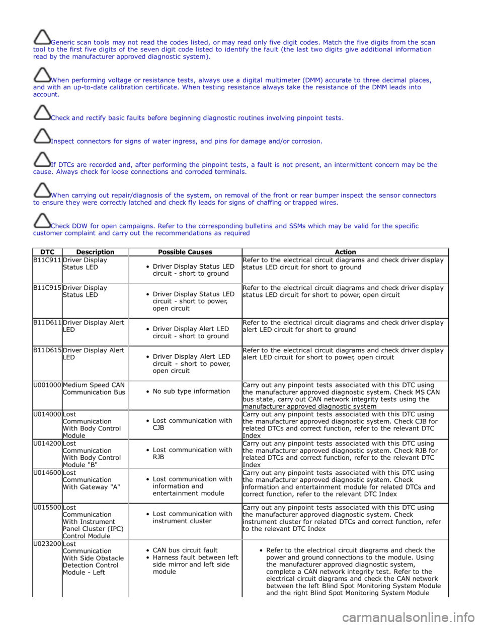
Generic scan tools may not read the codes listed, or may read only five digit codes. Match the five digits from the scan
tool to the first five digits of the seven digit code listed to identify the fault (the last two digits give additional information
read by the manufacturer approved diagnostic system).
When performing voltage or resistance tests, always use a digital multimeter (DMM) accurate to three decimal places,
and with an up-to-date calibration certificate. When testing resistance always take the resistance of the DMM leads into
account.
Check and rectify basic faults before beginning diagnostic routines involving pinpoint tests.
Inspect connectors for signs of water ingress, and pins for damage and/or corrosion.
If DTCs are recorded and, after performing the pinpoint tests, a fault is not present, an intermittent concern may be the
cause. Always check for loose connections and corroded terminals.
When carrying out repair/diagnosis of the system, on removal of the front or rear bumper inspect the sensor connectors
to ensure they were correctly latched and check fly leads for signs of chaffing or trapped wires.
Check DDW for open campaigns. Refer to the corresponding bulletins and SSMs which may be valid for the specific
customer complaint and carry out the recommendations as required
DTC Description Possible Causes Action B11C911
Driver Display
Status LED
Driver Display Status LED
circuit - short to ground Refer to the electrical circuit diagrams and check driver display
status LED circuit for short to ground B11C915
Driver Display
Status LED
Driver Display Status LED
circuit - short to power,
open circuit Refer to the electrical circuit diagrams and check driver display
status LED circuit for short to power, open circuit B11D611
Driver Display Alert
LED
Driver Display Alert LED
circuit - short to ground Refer to the electrical circuit diagrams and check driver display
alert LED circuit for short to ground B11D615
Driver Display Alert
LED
Driver Display Alert LED
circuit - short to power,
open circuit Refer to the electrical circuit diagrams and check driver display
alert LED circuit for short to power, open circuit U001000
Medium Speed CAN
Communication Bus
No sub type information Carry out any pinpoint tests associated with this DTC using
the manufacturer approved diagnostic system. Check MS CAN
bus state, carry out CAN network integrity tests using the
manufacturer approved diagnostic system U014000
Lost
Communication
With Body Control
Module
Lost communication with
CJB Carry out any pinpoint tests associated with this DTC using
the manufacturer approved diagnostic system. Check CJB for
related DTCs and correct function, refer to the relevant DTC
Index U014200
Lost
Communication
With Body Control
Module "B"
Lost communication with
RJB Carry out any pinpoint tests associated with this DTC using
the manufacturer approved diagnostic system. Check RJB for
related DTCs and correct function, refer to the relevant DTC
Index U014600
Lost
Communication
With Gateway "A"
Lost communication with
information and
entertainment module Carry out any pinpoint tests associated with this DTC using
the manufacturer approved diagnostic system. Check
information and entertainment module for related DTCs and
correct function, refer to the relevant DTC Index U015500
Lost
Communication
With Instrument
Panel Cluster (IPC)
Control Module
Lost communication with
instrument cluster Carry out any pinpoint tests associated with this DTC using
the manufacturer approved diagnostic system. Check
instrument cluster for related DTCs and correct function, refer
to the relevant DTC Index U023200
Lost
Communication
With Side Obstacle
Detection Control
Module - Left
CAN bus circuit fault
Harness fault between left
side mirror and left side
module
Refer to the electrical circuit diagrams and check the
power and ground connections to the module. Using
the manufacturer approved diagnostic system,
complete a CAN network integrity test. Refer to the
electrical circuit diagrams and check the CAN network
between the left Blind Spot Monitoring System Module
and the right Blind Spot Monitoring System Module
Page 1854 of 3039
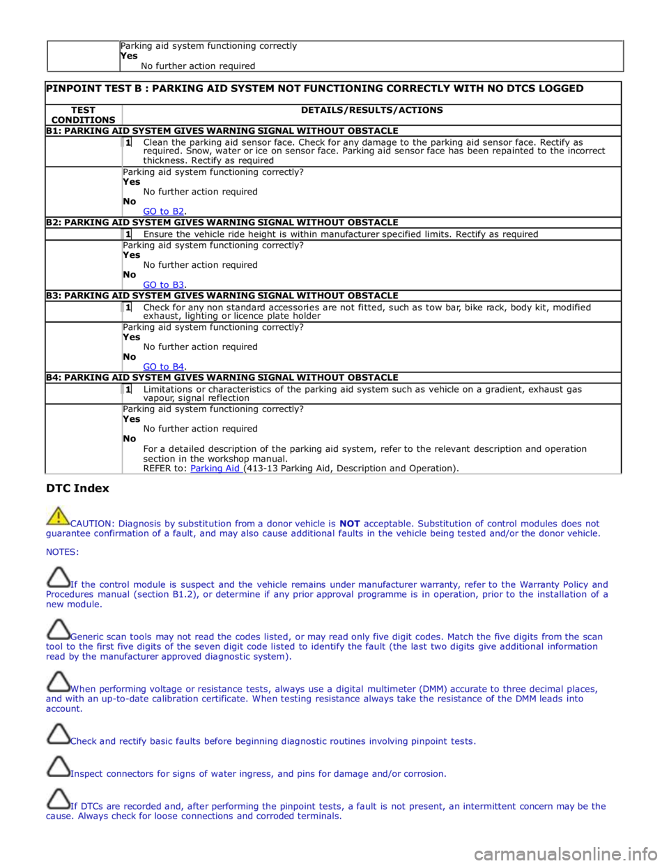
PINPOINT TEST B : PARKING AID SYSTEM NOT FUNCTIONING CORRECTLY WITH NO DTCS LOGGED TEST
CONDITIONS DETAILS/RESULTS/ACTIONS B1: PARKING AID SYSTEM GIVES WARNING SIGNAL WITHOUT OBSTACLE 1 Clean the parking aid sensor face. Check for any damage to the parking aid sensor face. Rectify as required. Snow, water or ice on sensor face. Parking aid sensor face has been repainted to the incorrect
thickness. Rectify as required Parking aid system functioning correctly? Yes
No further action required
No
GO to B2. B2: PARKING AID SYSTEM GIVES WARNING SIGNAL WITHOUT OBSTACLE 1 Ensure the vehicle ride height is within manufacturer specified limits. Rectify as required Parking aid system functioning correctly? Yes
No further action required
No
GO to B3. B3: PARKING AID SYSTEM GIVES WARNING SIGNAL WITHOUT OBSTACLE 1 Check for any non standard accessories are not fitted, such as tow bar, bike rack, body kit, modified exhaust, lighting or licence plate holder Parking aid system functioning correctly? Yes
No further action required
No
GO to B4. B4: PARKING AID SYSTEM GIVES WARNING SIGNAL WITHOUT OBSTACLE 1 Limitations or characteristics of the parking aid system such as vehicle on a gradient, exhaust gas vapour, signal reflection Parking aid system functioning correctly? Yes
No further action required
No
For a detailed description of the parking aid system, refer to the relevant description and operation
section in the workshop manual.
REFER to: Parking Aid (413-13 Parking Aid, Description and Operation). DTC Index
CAUTION: Diagnosis by substitution from a donor vehicle is NOT acceptable. Substitution of control modules does not
guarantee confirmation of a fault, and may also cause additional faults in the vehicle being tested and/or the donor vehicle.
NOTES:
If the control module is suspect and the vehicle remains under manufacturer warranty, refer to the Warranty Policy and
Procedures manual (section B1.2), or determine if any prior approval programme is in operation, prior to the installation of a
new module.
Generic scan tools may not read the codes listed, or may read only five digit codes. Match the five digits from the scan
tool to the first five digits of the seven digit code listed to identify the fault (the last two digits give additional information
read by the manufacturer approved diagnostic system).
When performing voltage or resistance tests, always use a digital multimeter (DMM) accurate to three decimal places,
and with an up-to-date calibration certificate. When testing resistance always take the resistance of the DMM leads into
account.
Check and rectify basic faults before beginning diagnostic routines involving pinpoint tests.
Inspect connectors for signs of water ingress, and pins for damage and/or corrosion.
If DTCs are recorded and, after performing the pinpoint tests, a fault is not present, an intermittent concern may be the
cause. Always check for loose connections and corroded terminals. Parking aid system functioning correctly
Yes
No further action required
Page 1858 of 3039

NOTE: The vehicle may take 30 seconds (or 100m) to learn the steering centre position after starting the engine. This is
normal. 1 Start the engine 2 Wait at least 30 seconds 3 Select reverse gear 4 Turn the steering wheel and observe the touch screen Do the tracking lines react to steering input? Yes
No fault present
No
Potential LIN data gateway fault DTC Index
For a list of Diagnostic Trouble Codes (DTCs) that could be logged on this vehicle, please refer to Section 100-00.
Page 1889 of 3039
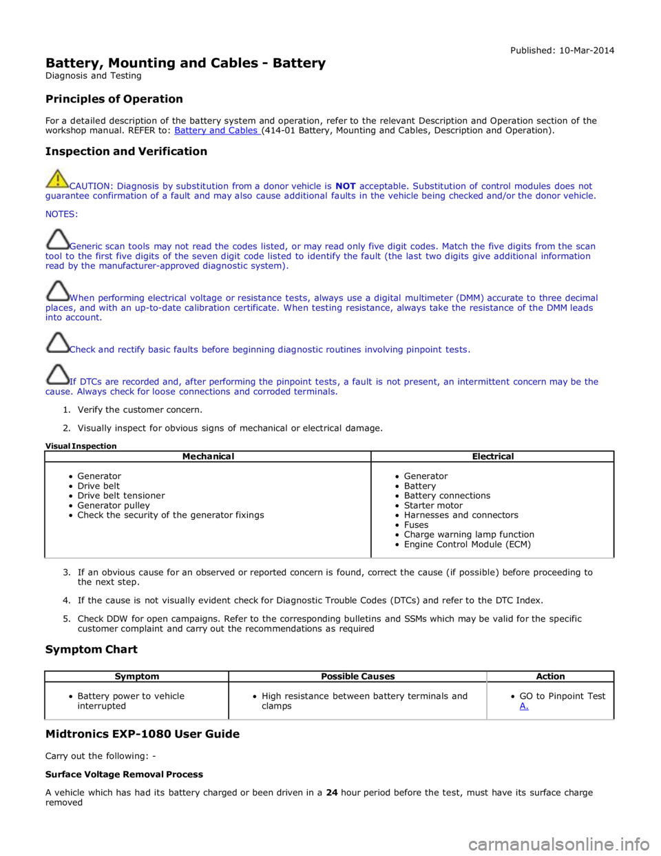
Battery, Mounting and Cables - Battery
Diagnosis and Testing
Principles of Operation Published: 10-Mar-2014
For a detailed description of the battery system and operation, refer to the relevant Description and Operation section of the
workshop manual. REFER to: Battery and Cables (414-01 Battery, Mounting and Cables, Description and Operation).
Inspection and Verification
CAUTION: Diagnosis by substitution from a donor vehicle is NOT acceptable. Substitution of control modules does not
guarantee confirmation of a fault and may also cause additional faults in the vehicle being checked and/or the donor vehicle.
NOTES:
Generic scan tools may not read the codes listed, or may read only five digit codes. Match the five digits from the scan
tool to the first five digits of the seven digit code listed to identify the fault (the last two digits give additional information
read by the manufacturer-approved diagnostic system).
When performing electrical voltage or resistance tests, always use a digital multimeter (DMM) accurate to three decimal
places, and with an up-to-date calibration certificate. When testing resistance, always take the resistance of the DMM leads
into account.
Check and rectify basic faults before beginning diagnostic routines involving pinpoint tests.
If DTCs are recorded and, after performing the pinpoint tests, a fault is not present, an intermittent concern may be the
cause. Always check for loose connections and corroded terminals.
1. Verify the customer concern.
2. Visually inspect for obvious signs of mechanical or electrical damage.
Visual Inspection
Mechanical Electrical
Generator
Drive belt
Drive belt tensioner
Generator pulley
Check the security of the generator fixings
Generator
Battery
Battery connections
Starter motor
Harnesses and connectors
Fuses
Charge warning lamp function
Engine Control Module (ECM)
3. If an obvious cause for an observed or reported concern is found, correct the cause (if possible) before proceeding to
the next step.
4. If the cause is not visually evident check for Diagnostic Trouble Codes (DTCs) and refer to the DTC Index.
5. Check DDW for open campaigns. Refer to the corresponding bulletins and SSMs which may be valid for the specific
customer complaint and carry out the recommendations as required
Symptom Chart
Symptom Possible Causes Action
Battery power to vehicle
interrupted
High resistance between battery terminals and
clamps
GO to Pinpoint Test
A. Midtronics EXP-1080 User Guide
Carry out the following: -
Surface Voltage Removal Process
A vehicle which has had its battery charged or been driven in a 24 hour period before the test, must have its surface charge
removed