2010 JAGUAR XFR list
[x] Cancel search: listPage 1123 of 3039

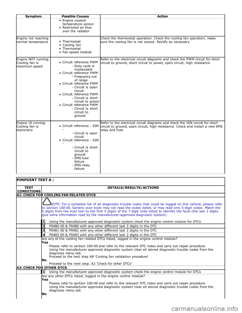
Symptom Possible Causes Action Engine coolant
temperature sensor
Restricted air flow
over the radiator Engine not reaching
normal temperature
Thermostat
Cooling fan
Thermostat
Fan speed module Check the thermostat operation. Check the cooling fan operation, make
sure the cooling fan is not seized. Rectify as necessary Engine NOT running.
Cooling fan is
maximum speed
Circuit reference PWM
- Duty cycle is
implausible
Circuit reference PWM
- Frequency out
of range
Circuit reference PWM
- Circuit is open
circuit
Circuit reference PWM
- Circuit is short
circuit to power
Circuit reference PWM
- Circuit is short
circuit to
ground Refer to the electrical circuit diagrams and check the PWM circuit for short
circuit to ground, short circuit to power, open circuit, high resistance Engine IS running.
Cooling fan is
stationary
Circuit reference - IGN
-
- Circuit is open
circuit
Circuit reference - IGN
-
- Circuit is short
circuit to
ground
- EMS fuse
failure
- EMS relay
failure Refer to the electrical circuit diagrams and check the IGN circuit for short
circuit to ground, open circuit, high resistance. Check and install a new EMS
relay and fuse
PINPOINT TEST A : TEST
CONDITIONS DETAILS/RESULTS/ACTIONS A1: CHECK FOR COOLING FAN RELATED DTCS
NOTE: For a complete list of all diagnostic trouble codes that could be logged on this vehicle, please refer
to section 100-00. Generic scan tools may not read the codes listed, or may read only 5-digit codes. Match the
5 digits from the scan tool to the first 5 digits of the 7-digit code listed to identify the fault (the last 2 digits
give extra information read by the manufacturer-approved diagnostic system). 1 Using the manufacturer approved diagnostic system check the engine control module for DTCs 2 P0480-00 & P0480 with any other different last 2 digits in the DTC 3 P0481-00 & P0481 with any other different last 2 digits in the DTC 4 P0483-00 & P0483 with any other different last 2 digits in the DTC Are any of the cooling fan related DTCs listed, logged in the engine control module?
Yes
Please refer to section 100-00 and refer to the relevant DTC index and carry out repair procedure
Using the manufacturer approved diagnostic system clear all stored diagnostic trouble codes from the
diagnosis menu tab
Proceed to the test step A9 'Cooling fan validation procedure'
No
Proceed to the next step. A2 'Check for other DTCs' A2: CHECK FOR OTHER DTCS 1 Using the manufacturer approved diagnostic system check the engine control module for DTCs Are any other DTCs listed, logged in the engine control module?
Yes
Please refer to section 100-00 and refer to the relevant DTC index and carry out repair procedure
Using the manufacturer approved diagnostic system clear all stored diagnostic trouble codes from the
diagnosis menu tab
No
Page 1125 of 3039

- Megafuse fixing nuts
Engine junction box
- Megafuse
- Megafuse fixing nuts
- Fuses
- Engine control module relay Were any circuits or wiring short circuit to ground, short circuit to power, open circuit, high resistance or any
connectors damaged from water ingress, pin damage and/or corrosion?
Yes
Rectify as required
No
Proceed to the next step. A9 'Cooling fan validation procedure' A9: COOLING FAN VALIDATION PROCEDURE 1 Ensure the hood is closed 2 Allow vehicle to idle 3 Switch ON air conditioning and set to lowest temperature and highest fan speed 4 Allow vehicle to reach operating temperature (approximately 90 degrees C). Using the manufacturer approved diagnostic system monitor datalogger signals – Engine Coolant Temperature (0XF405) -and -
Electric Fan PWM Control - Commanded (0X03F9) - as the engine coolant temperature reaches
operating temperature the fan speed should also increase between the values of 9 and 90% Did the cooling fan rotate at increasing speed as engine coolant temperature increased?
Yes
Return vehicle to customer
No
Contact dealer technical support DTC Index
For a list of diagnostic trouble codes (DTCs) that could be logged on this vehicle, please refer to Section 100-00.
REFER to: Electronic Engine Controls (303-14D Electronic Engine Controls - V8 S/C 5.0L Petrol, Diagnosis and Testing). www.JagDocs.com
Page 1188 of 3039

Symptom Possible Causes Action Purge valve
Difficult hot start
Injector leak
Electronic engine control
Purge valve
Fuel pump
Ignition system
EGR valve stuck open Check for injector leak, install new injector as required.
Check for electronic engine controls, evaporative emissions,
fuel system, ignition system and engine emission system
related DTCs and refer to the relevant DTC Index Difficult to start after hot
soak (vehicle standing,
engine off, after engine has
reached operating
temperature)
Injector leak
Electronic engine control
Purge valve
Fuel pump
Ignition system
EGR valve stuck open Check for injector leak, install new injector as required.
Check for electronic engine controls, evaporative emissions,
fuel system, ignition system and engine emission system
related DTCs and refer to the relevant DTC Index Engine stalls soon after start
Breather system
disconnected/restricted
ECM relay
Electronic engine control
Ignition system
Air intake system restricted
Air leakage
Fuel lines Ensure the engine breather system is free from restriction
and is correctly installed. Check for electronic engine
control, ignition system and fuel system related DTCs and
refer to the relevant DTC Index. Check for blockage in air
filter element and air intake system. Check for air leakage
in air intake system Engine hesitates/poor
acceleration
Fuel pressure, fuel pump,
fuel lines
Injector leak
Air leakage
Electronic engine control
Throttle motor
Restricted accelerator pedal
travel (carpet, etc)
Ignition system
EGR valve stuck open
Transmission malfunction Check for fuel system related DTCs and refer to the
relevant DTC Index. Check for injector leak, install new
injector as required. Check for air leakage in air intake
system. Ensure accelerator pedal is free from restriction.
Check for electronic engine controls, ignition, engine
emission system and transmission related DTCs and refer
to the relevant DTC Index Engine backfires
Fuel pump/lines
Air leakage
Electronic engine controls
Ignition system
Sticking variable camshaft
timing (VCT) hub Check for fuel system failures. Check for air leakage in
intake air system. Check for electronic engine controls,
ignition system and VCT system related DTCs and refer to
the relevant DTC Index Engine surges
Fuel pump/lines
Electronic engine controls
Throttle motor
Ignition system Check for fuel system failures. Check for electronic engine
controls, throttle system and ignition system related DTCs
and refer to the relevant DTC Index Engine detonates/knocks
Fuel pump/lines
Air leakage
Electronic engine controls
Sticking VCT hub Check for fuel system failures. Check for air leakage in
intake air system. Check for electronic engine controls and
VCT system related DTCs and refer to the relevant DTC
Index No throttle response
Electronic engine controls
Throttle motor Check for electronic engine controls and throttle system
related DTCs and refer to the relevant DTC Index Poor throttle response
Breather system
disconnected/restricted
Electronic engine control
Transmission malfunction
Traction control event Air
leakage Ensure the engine breather system is free from restriction
and is correctly installed. Check for electronic engine
controls, transmission and traction control related DTCs and
refer to the related DTC Index. Check for air leakage in
intake air system DTC Index
For a list of Diagnostic Trouble Codes (DTCs) that could be logged in the Engine Control Module (ECM), please refer to Section
303-14.
REFER to: Electronic Engine Controls (303-14C Electronic Engine Controls - V8 5.0L Petrol, Diagnosis and Testing) / Electronic Engine Controls (303-14D Electronic Engine Controls - V8 S/C 5.0L Petrol, Diagnosis and Testing).
Page 1264 of 3039

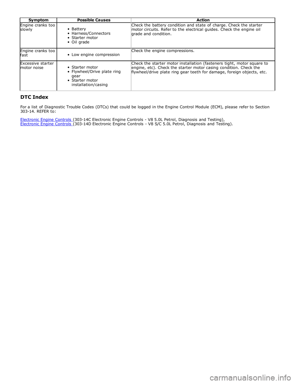
Symptom Possible Causes Action Engine cranks too
slowly
Battery
Harness/Connectors
Starter motor
Oil grade Check the battery condition and state of charge. Check the starter
motor circuits. Refer to the electrical guides. Check the engine oil
grade and condition. Engine cranks too
fast
Low engine compression Check the engine compressions. Excessive starter
motor noise
Starter motor
Flywheel/Drive plate ring
gear
Starter motor
installation/casing Check the starter motor installation (fasteners tight, motor square to
engine, etc). Check the starter motor casing condition. Check the
flywheel/drive plate ring gear teeth for damage, foreign objects, etc. DTC Index
For a list of Diagnostic Trouble Codes (DTCs) that could be logged in the Engine Control Module (ECM), please refer to Section
303-14. REFER to:
Electronic Engine Controls (303-14C Electronic Engine Controls - V8 5.0L Petrol, Diagnosis and Testing), Electronic Engine Controls (303-14D Electronic Engine Controls - V8 S/C 5.0L Petrol, Diagnosis and Testing).
Page 1265 of 3039

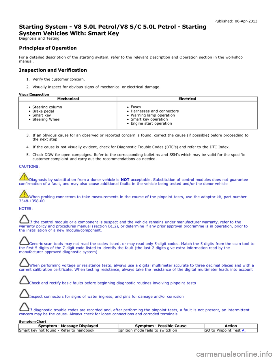
Starting System - V8 5.0L Petrol/V8 S/C 5.0L Petrol - Starting
System Vehicles With: Smart Key
Diagnosis and Testing
Principles of Operation Published: 06-Apr-2013
For a detailed description of the starting system, refer to the relevant Description and Operation section in the workshop
manual.
Inspection and Verification
1. Verify the customer concern.
2. Visually inspect for obvious signs of mechanical or electrical damage.
Visual Inspection
Mechanical Electrical
Steering column
Brake pedal
Smart key
Steering Wheel
Fuses
Harnesses and connectors
Warning lamp operation
Smart key operation
Engine start operation
3. If an obvious cause for an observed or reported concern is found, correct the cause (if possible) before proceeding to
the next step.
4. If the cause is not visually evident, check for Diagnostic Trouble Codes (DTC's) and refer to the DTC Index.
5. Check DDW for open campaigns. Refer to the corresponding bulletins and SSM's which may be valid for the specific
customer complaint and carry out the recommendations as needed.
CAUTIONS:
Diagnosis by substitution from a donor vehicle is NOT acceptable. Substitution of control modules does not guarantee
confirmation of a fault, and may also cause additional faults in the vehicle being tested and/or the donor vehicle
When probing connectors to take measurements in the course of the pinpoint tests, use the adaptor kit, part number
3548-1358-00
NOTES:
If the control module or a component is suspect and the vehicle remains under manufacturer warranty, refer to the
warranty policy and procedures manual (section B1.2), or determine if any prior approval programme is in operation, prior to
the installation of a new module/component.
Generic scan tools may not read the codes listed, or may read only 5-digit codes. Match the 5 digits from the scan tool to
the first 5 digits of the 7-digit code listed to identify the fault (the last 2 digits give extra information read by the
manufacturer-approved diagnostic system)
When performing voltage or resistance tests, always use a digital multimeter accurate to three decimal places and with a
current calibration certificate. When testing resistance, always take the resistance of the digital multimeter leads into account
Check and rectify basic faults before beginning diagnostic routines involving pinpoint tests
Inspect connectors for signs of water ingress, and pins for damage and/or corrosion
If diagnostic trouble codes are recorded and, after performing the pinpoint tests, a fault is not present, an intermittent
concern may be the cause. Always check for loose connections and corroded terminals
Symptom Chart
Symptom - Message Displayed Symptom - Possible Cause Action Smart key not found - Refer to handbook Ignition mode fails to switch on GO to Pinpoint Test A.
Page 1277 of 3039

Symptom Possible Causes Action Difficult hot start
Injector leak
Electronic engine control
Purge valve
Fuel pump
Ignition system
EGR valve stuck open Check for injector leak, install new injector as required.
Check for electronic engine controls, evaporative emissions,
fuel system, ignition system and engine emission system
related DTCs and refer to the relevant DTC Index Difficult to start after hot
soak (vehicle standing,
engine off, after engine has
reached operating
temperature)
Injector leak
Electronic engine control
Purge valve
Fuel pump
Ignition system
EGR valve stuck open Check for injector leak, install new injector as required.
Check for electronic engine controls, evaporative emissions,
fuel system, ignition system and engine emission system
related DTCs and refer to the relevant DTC Index Engine stalls soon after start
Breather system
disconnected/restricted
ECM relay
Electronic engine control
Ignition system
Air intake system restricted
Air leakage
Fuel lines Ensure the engine breather system is free from restriction
and is correctly installed. Check for electronic engine
control, ignition system and fuel system related DTCs and
refer to the relevant DTC Index. Check for blockage in air
filter element and air intake system. Check for air leakage
in air intake system Engine hesitates/poor
acceleration
Fuel pressure, fuel pump,
fuel lines
Injector leak
Air leakage
Electronic engine control
Throttle motor
Restricted accelerator pedal
travel (carpet, etc)
Ignition system
EGR valve stuck open
Transmission malfunction Check for fuel system related DTCs and refer to the
relevant DTC Index. Check for injector leak, install new
injector as required. Check for air leakage in air intake
system. Ensure accelerator pedal is free from restriction.
Check for electronic engine controls, ignition, engine
emission system and transmission related DTCs and refer
to the relevant DTC Index Engine backfires
Fuel pump/lines
Air leakage
Electronic engine controls
Ignition system
Sticking variable camshaft
timing (VCT) hub Check for fuel system failures. Check for air leakage in
intake air system. Check for electronic engine controls,
ignition system and VCT system related DTCs and refer to
the relevant DTC Index Engine surges
Fuel pump/lines
Electronic engine controls
Throttle motor
Ignition system Check for fuel system failures. Check for electronic engine
controls, throttle system and ignition system related DTCs
and refer to the relevant DTC Index Engine detonates/knocks
Fuel pump/lines
Air leakage
Electronic engine controls
Sticking VCT hub Check for fuel system failures. Check for air leakage in
intake air system. Check for electronic engine controls and
VCT system related DTCs and refer to the relevant DTC
Index No throttle response
Electronic engine controls
Throttle motor Check for electronic engine controls and throttle system
related DTCs and refer to the relevant DTC Index Poor throttle response
Breather system
disconnected/restricted
Electronic engine control
Transmission malfunction
Traction control event Air
leakage Ensure the engine breather system is free from restriction
and is correctly installed. Check for electronic engine
controls, transmission and traction control related DTCs and
refer to the related DTC Index. Check for air leakage in
intake air system DTC Index
For a list of Diagnostic Trouble Codes (DTCs) that could be logged in the Engine Control Module (ECM), please refer to Section
303-14. REFER to:
Electronic Engine Controls (303-14C Electronic Engine Controls - V8 5.0L Petrol, Diagnosis and Testing), Electronic Engine Controls (303-14D Electronic Engine Controls - V8 S/C 5.0L Petrol, Diagnosis and Testing).
Page 1284 of 3039

Symptom Possible Causes Action Breather system
disconnected/restricted DTC Index
For a list of Diagnostic Trouble Codes (DTCs) that could be logged in the Engine Control Module (ECM), please refer to Section
303-14. REFER to:
Electronic Engine Controls (303-14C Electronic Engine Controls - V8 5.0L Petrol, Diagnosis and Testing), Electronic Engine Controls (303-14D Electronic Engine Controls - V8 S/C 5.0L Petrol, Diagnosis and Testing).
Page 1349 of 3039

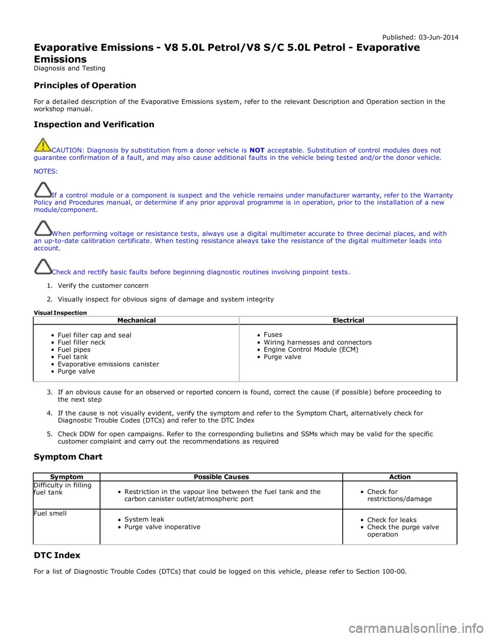
Published: 03-Jun-2014
Evaporative Emissions - V8 5.0L Petrol/V8 S/C 5.0L Petrol - Evaporative
Emissions
Diagnosis and Testing
Principles of Operation
For a detailed description of the Evaporative Emissions system, refer to the relevant Description and Operation section in the
workshop manual.
Inspection and Verification
CAUTION: Diagnosis by substitution from a donor vehicle is NOT acceptable. Substitution of control modules does not
guarantee confirmation of a fault, and may also cause additional faults in the vehicle being tested and/or the donor vehicle.
NOTES:
If a control module or a component is suspect and the vehicle remains under manufacturer warranty, refer to the Warranty
Policy and Procedures manual, or determine if any prior approval programme is in operation, prior to the installation of a new
module/component.
When performing voltage or resistance tests, always use a digital multimeter accurate to three decimal places, and with
an up-to-date calibration certificate. When testing resistance always take the resistance of the digital multimeter leads into
account.
Check and rectify basic faults before beginning diagnostic routines involving pinpoint tests.
1. Verify the customer concern
2. Visually inspect for obvious signs of damage and system integrity
Visual Inspection
Mechanical Electrical
Fuel filler cap and seal
Fuel filler neck
Fuel pipes
Fuel tank
Evaporative emissions canister
Purge valve
Fuses
Wiring harnesses and connectors
Engine Control Module (ECM)
Purge valve
3. If an obvious cause for an observed or reported concern is found, correct the cause (if possible) before proceeding to
the next step
4. If the cause is not visually evident, verify the symptom and refer to the Symptom Chart, alternatively check for
Diagnostic Trouble Codes (DTCs) and refer to the DTC Index
5. Check DDW for open campaigns. Refer to the corresponding bulletins and SSMs which may be valid for the specific
customer complaint and carry out the recommendations as required
Symptom Chart
Symptom Possible Causes Action Difficulty in filling
fuel tank
Restriction in the vapour line between the fuel tank and the
carbon canister outlet/atmospheric port
Check for
restrictions/damage Fuel smell
System leak
Purge valve inoperative
Check for leaks
Check the purge valve
operation DTC Index
For a list of Diagnostic Trouble Codes (DTCs) that could be logged on this vehicle, please refer to Section 100-00.