2009 SUBARU TRIBECA Rear diff
[x] Cancel search: Rear diffPage 1680 of 2453
GD(H6DO)-68
Diagnostic Trouble Code (DTC) Detecting Criteria
GENERAL DESCRIPTION
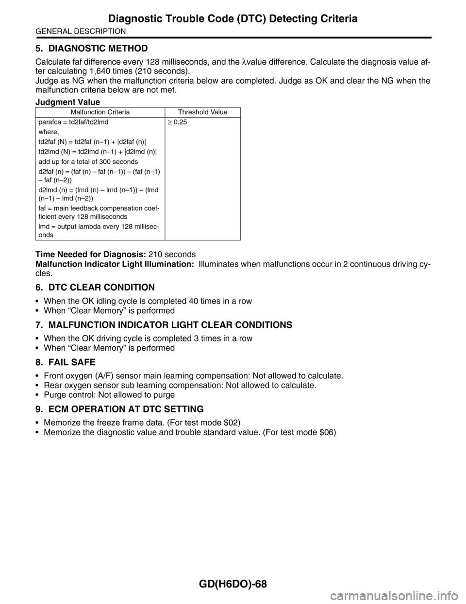
5. DIAGNOSTIC METHOD
Calculate faf difference every 128 milliseconds, and the λvalue difference. Calculate the diagnosis value af-
ter calculating 1,640 times (210 seconds).
Judge as NG when the malfunction criteria below are completed. Judge as OK and clear the NG when the
malfunction criteria below are not met.
Time Needed for Diagnosis: 210 seconds
Malfunction Indicator Light Illumination: Illuminates when malfunctions occur in 2 continuous driving cy-
cles.
6. DTC CLEAR CONDITION
•When the OK idling cycle is completed 40 times in a row
•When “Clear Memory” is performed
7. MALFUNCTION INDICATOR LIGHT CLEAR CONDITIONS
•When the OK driving cycle is completed 3 times in a row
•When “Clear Memory” is performed
8. FAIL SAFE
•Front oxygen (A/F) sensor main learning compensation: Not allowed to calculate.
•Rear oxygen sensor sub learning compensation: Not allowed to calculate.
•Purge control: Not allowed to purge
9. ECM OPERATION AT DTC SETTING
•Memorize the freeze frame data. (For test mode $02)
•Memorize the diagnostic value and trouble standard value. (For test mode $06)
Judgment Value
Malfunction Criteria Threshold Value
parafca = td2faf/td2lmd≥ 0.25
where,
td2faf (N) = td2faf (n–1) + |d2faf (n)|
td2lmd (N) = td2lmd (n–1) + |d2lmd (n)|
add up for a total of 300 seconds
d2faf (n) = (faf (n) – faf (n–1)) – (faf (n–1)
– faf (n–2))
d2lmd (n) = (lmd (n) – lmd (n–1)) – (lmd
(n–1) – lmd (n–2))
faf = main feedback compensation coef-
ficient every 128 milliseconds
lmd = output lambda every 128 millisec-
onds
Page 1734 of 2453
GD(H6DO)-122
Diagnostic Trouble Code (DTC) Detecting Criteria
GENERAL DESCRIPTION
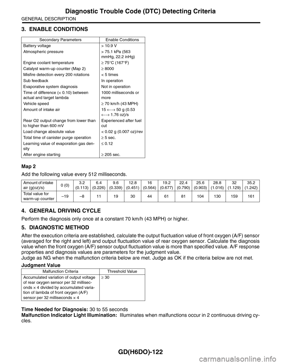
3. ENABLE CONDITIONS
Map 2
Add the following value every 512 milliseconds.
4. GENERAL DRIVING CYCLE
Perform the diagnosis only once at a constant 70 km/h (43 MPH) or higher.
5. DIAGNOSTIC METHOD
After the execution criteria are established, calculate the output fluctuation value of front oxygen (A/F) sensor
(averaged for the right and left) and output fluctuation value of rear oxygen sensor. Calculate the diagnosis
value when the front oxygen (A/F) sensor output fluctuation value is more than specified value. A/F response
properties and diagnosis values are parameters for the judgment value.
Judge as NG when the malfunction criteria below are met. Judge as OK if the criteria below are not met.
Time Needed for Diagnosis: 30 to 55 seconds
Malfunction Indicator Light Illumination: Illuminates when malfunctions occur in 2 continuous driving cy-
cles.
Secondary Parameters Enable Conditions
Battery voltage > 10.9 V
Atmospheric pressure > 75.1 kPa (563
mmHg, 22.2 inHg)
Engine coolant temperature≥ 75°C (167°F)
Catalyst warm-up counter (Map 2)≥ 8000
Misfire detection every 200 rotations < 5 times
Sub feedback In operation
Evaporative system diagnosis Not in operation
Time of difference (< 0.10) between
actual and target lambda
1000 milliseconds or
more
Ve h i c l e s p e e d≥ 70 km/h (43 MPH)
Amount of intake air 15 ←→ 50 g (0.53
←→ 1.76 oz)/s
Rear O2 output change from lower than
to higher than 600 mV
Experienced after fuel
cut
Load change absolute value < 0.02 g (0.007 oz)/rev
To t a l t i m e o f c a n i s t e r p u r g e o p e r a t i o n≥ 5 sec.
Learning value of evaporation gas den-
sity
≤ 0.12
After engine starting≥ 205 sec.
Amount of intake
air (g(oz)/s)0 (0)3.2
(0.113)
6.4
(0.226)
9.6
(0.339)
12.8
(0.451)
16
(0.564)
19.2
(0.677)
22.4
(0.790)
25.6
(0.903)
28.8
(1.016)
32
(1.129)
35.2
(1.242)
To t a l v a l u e f o r
warm-up counter–19 –8 11 19 30 44 61 81 104 130 159 161
Judgment Value
Malfunction Criteria Threshold Value
Accumulated variation of output voltage
of rear oxygen sensor per 32 millisec-
onds × 4 divided by accumulated varia-
tion of lambda of front oxygen (A/F)
sensor per 32 milliseconds × 4
≥ 30
Page 1917 of 2453
ME(H6DO)-51
Rear Chain Cover
MECHANICAL
18.Rear Chain Cover
A: REMOVAL
1) Remove the crank pulley.
2) Remove the front chain cover.
3) Remove the timing chain.
4) Remove the cam sprocket.
5) Remove the crank sprocket.
6) Remove the oil pump.
7) Remove the water pump.
8) Remove the rear chain cover.
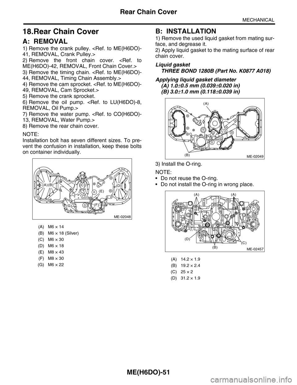
NOTE:
Installation bolt has seven different sizes. To pre-
vent the confusion in installation, keep these bolts
on container individually.
B: INSTALLATION
1) Remove the used liquid gasket from mating sur-
face, and degrease it.
2) Apply liquid gasket to the mating surface of rear
chain cover.
Liquid gasket
THREE BOND 1280B (Part No. K0877 A018)
Applying liquid gasket diameter
(A) 1.0±0.5 mm (0.039±0.020 in)
(B) 3.0±1.0 mm (0.118±0.039 in)
3) Install the O-ring.
NOTE:
•Do not reuse the O-ring.
•Do not install the O-ring in wrong place.
(A) M6 × 14
(B) M6 × 18 (Silver)
(C) M6 × 30
(D) M6 × 18
(E) M8 × 43
(F) M8 × 30
(G) M6 × 22
ME-02048
(F)
(C)(D)
(E)
(G)
(A)(B)
(A) 14.2 × 1.9
(B) 19.2 × 2.4
(C) 25 × 2
(D) 31.2 × 1.9
(A)
(B)ME-02049
(B)
(D)(C)
(A)(A)
ME-02457
Page 1929 of 2453
ME(H6DO)-63
Cylinder Block
MECHANICAL
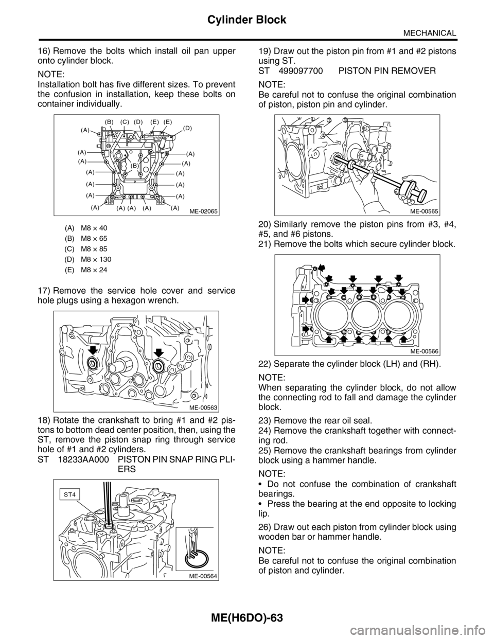
16) Remove the bolts which install oil pan upper
onto cylinder block.
NOTE:
Installation bolt has five different sizes. To prevent
the confusion in installation, keep these bolts on
container individually.
17) Remove the service hole cover and service
hole plugs using a hexagon wrench.
18) Rotate the crankshaft to bring #1 and #2 pis-
tons to bottom dead center position, then, using the
ST, remove the piston snap ring through service
hole of #1 and #2 cylinders.
ST 18233AA000 PISTON PIN SNAP RING PLI-
ERS
19) Draw out the piston pin from #1 and #2 pistons
using ST.
ST 499097700 PISTON PIN REMOVER
NOTE:
Be careful not to confuse the original combination
of piston, piston pin and cylinder.
20) Similarly remove the piston pins from #3, #4,
#5, and #6 pistons.
21) Remove the bolts which secure cylinder block.
22) Separate the cylinder block (LH) and (RH).
NOTE:
When separating the cylinder block, do not allow
the connecting rod to fall and damage the cylinder
block.
23) Remove the rear oil seal.
24) Remove the crankshaft together with connect-
ing rod.
25) Remove the crankshaft bearings from cylinder
block using a hammer handle.
NOTE:
•Do not confuse the combination of crankshaft
bearings.
•Press the bearing at the end opposite to locking
lip.
26) Draw out each piston from cylinder block using
wooden bar or hammer handle.
NOTE:
Be careful not to confuse the original combination
of piston and cylinder.
(A) M8 × 40
(B) M8 × 65
(C) M8 × 85
(D) M8 × 130
(E) M8 × 24
ME-02065
(D)(E)
(A)
(A)
(A)
(A)
(A)
(A)
(A)
(E)
(A)(A)(A)
(C)(B)
(A)
(D)
(A)
(A)
(A)
(A)
(A)
(B)
ME-00563
ST4
ME-00564
ME-00565
ME-00566
Page 1986 of 2453
PM-3
Schedule
PERIODIC MAINTENANCE SERVICES
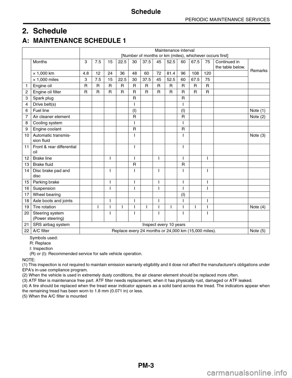
2. Schedule
A: MAINTENANCE SCHEDULE 1
Symbols used:
R: Replace
I: Inspection
(R) or (I): Recommended service for safe vehicle operation.
NOTE:(1) This inspection is not required to maintain emission warranty eligibility and it dose not affect the manufacturer's obligations under
EPA's in-use compliance program.
(2) When the vehicle is used in extremely dusty conditions, the air cleaner element should be replaced more often.
(3) ATF filter is maintenance free part. ATF filter needs replacement, when it has physically rust, damaged or ATF leaked.
(4) A tire should be replaced when the tread wear indicator appears as a solid band across the tread. The indicators appear when
the remaining tread has been worn to 1.8 mm (0.071 in) or less.
(5) When the A/C filter is mounted
Maintenance interval
[Number of months or km (miles), whichever occurs first]
Months 3 7.51522.53037.54552.56067.575Continued in
the table below.Remarks× 1,000 km 4.8 12 24 36 48 60 72 81.4 96 108 120
× 1,000 miles 3 7.5 15 22.5 30 37.5 45 52.5 60 67.5 75
1Engine oil R R R R R R R R R R R
2Engine oil filter R R R R R R R R R R R
3Spark plug R R
4Drive belt(s) I I
6Fuel line (I) (I) Note (1)
7Air cleaner element R R Note (2)
8Cooling system I I
9Engine coolant R R
10 Automatic transmis-
sion fluid
I I Note (3)
11 Front & rear differential
oil
I I
12 Brake line I I I I I
13 Brake fluid R R
14 Disc brake pad and
disc
I I I I I
15 Parking brake I I I I I
16 Suspension I I I I I
17 Wheel bearing (I)
18 Axle boots and joints I I I I I
19 Tire rotation I I I I I I I I I I Note (4)
20 Steering system
(Power steering)
I I I I I
21 SRS airbag system Inspect every 10 years
22 A/C filter Replace every 24 months or 24,000 km (15,000 miles). Note (5)
Page 1987 of 2453
PM-4
Schedule
PERIODIC MAINTENANCE SERVICES
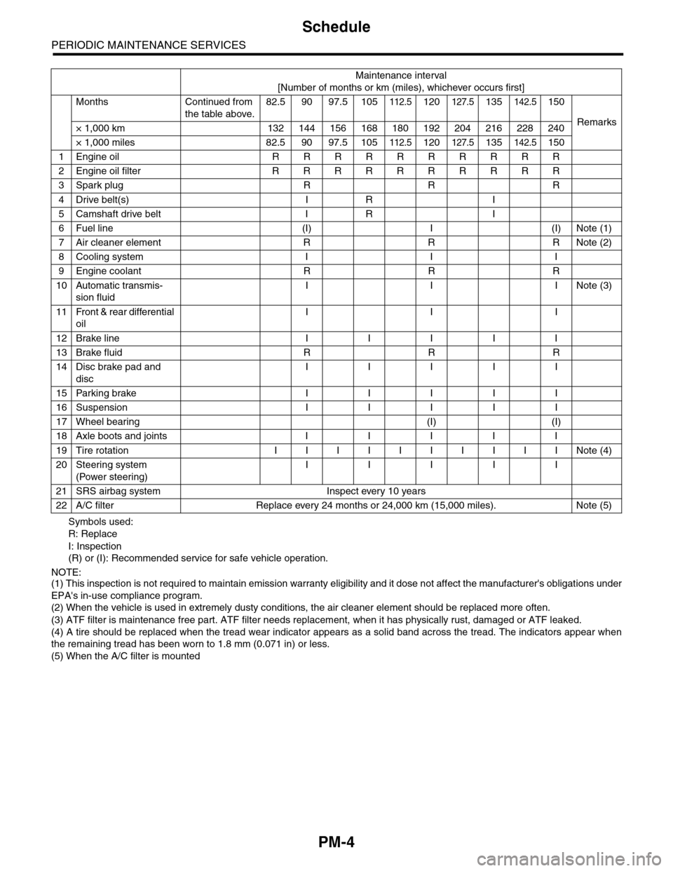
Symbols used:
R: Replace
I: Inspection
(R) or (I): Recommended service for safe vehicle operation.
NOTE:(1) This inspection is not required to maintain emission warranty eligibility and it dose not affect the manufacturer's obligations under
EPA's in-use compliance program.
(2) When the vehicle is used in extremely dusty conditions, the air cleaner element should be replaced more often.
(3) ATF filter is maintenance free part. ATF filter needs replacement, when it has physically rust, damaged or ATF leaked.
(4) A tire should be replaced when the tread wear indicator appears as a solid band across the tread. The indicators appear when
the remaining tread has been worn to 1.8 mm (0.071 in) or less.
(5) When the A/C filter is mounted
Maintenance interval
[Number of months or km (miles), whichever occurs first]
Months Continued from
the table above.
82.5 90 97.5 105112.5120127.5135142.5150
Remarks× 1,000 km 132 144 156 168 180 192 204 216 228 240
× 1,000 miles 82.5 90 97.5 105112.5120127.5135142.5150
1Engine oil R R R R R R R R R R
2Engine oil filter R R R R R R R R R R
3Spark plug R R R
4Drive belt(s) I R I
5Camshaft drive belt I R I
6Fuel line (I) I (I) Note (1)
7Air cleaner element R R R Note (2)
8Cooling system I I I
9Engine coolant R R R
10 Automatic transmis-
sion fluid
I I INote (3)
11 Front & rear differential
oil
I I I
12 Brake line I I I I I
13 Brake fluid R R R
14 Disc brake pad and
disc
I I I I I
15 Parking brake I I I I I
16 Suspension I I I I I
17 Wheel bearing (I) (I)
18 Axle boots and joints I I I I I
19 Tire rotation I I I I I I I I I I Note (4)
20 Steering system
(Power steering)
I I I I I
21 SRS airbag system Inspect every 10 years
22 A/C filter Replace every 24 months or 24,000 km (15,000 miles). Note (5)
Page 2001 of 2453
PM-18
Front & Rear Differential Oil
PERIODIC MAINTENANCE SERVICES
12.Front & Rear Differential Oil
A: REPLACEMENT
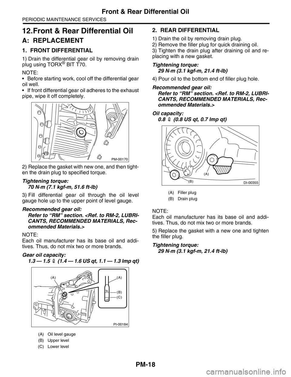
1. FRONT DIFFERENTIAL
1) Drain the differential gear oil by removing drain
plug using TORX® BIT T70.
NOTE:
•Before starting work, cool off the differential gear
oil well.
•If front differential gear oil adheres to the exhaust
pipe, wipe it off completely.
2) Replace the gasket with new one, and then tight-
en the drain plug to specified torque.
Tightening torque:
70 N·m (7.1 kgf-m, 51.6 ft-lb)
3) Fill differential gear oil through the oil level
gauge hole up to the upper point of level gauge.
Recommended gear oil:
Refer to “RM” section.
ommended Materials.>
NOTE:
Each oil manufacturer has its base oil and addi-
tives. Thus, do not mix two or more brands.
Gear oil capacity:
1.3 — 1.5 2 (1 . 4 — 1 .6 U S q t , 1 . 1 — 1 .3 lmp q t)
2. REAR DIFFERENTIAL
1) Drain the oil by removing drain plug.
2) Remove the filler plug for quick draining oil.
3) Tighten the drain plug after draining oil and re-
placing with a new gasket.
Tightening torque:
29 N·m (3.1 kgf-m, 21.4 ft-lb)
4) Pour oil to the bottom end of filler plug hole.
Recommended gear oil:
Refer to “RM” section.
ommended Materials.>
Oil capacity:
0.8 2 (0.8 US qt, 0.7 lmp qt)
NOTE:
Each oil manufacturer has its base oil and addi-
tives. Thus, do not mix two or more brands.
5) Replace the gasket with a new one and tighten
the filler plug.
Tightening torque:
29 N·m (3.1 kgf-m, 21.4 ft-lb)
(A) Oil level gauge
(B) Upper level
(C) Lower level
PM-00170
PI-00184
(A)
(C)
(B)
(A)
F
L
(A) Filler plug
(B) Drain plug
(B)DI-00355
(A)
Page 2002 of 2453
PM-19
Brake Line
PERIODIC MAINTENANCE SERVICES
13.Brake Line
A: INSPECTION
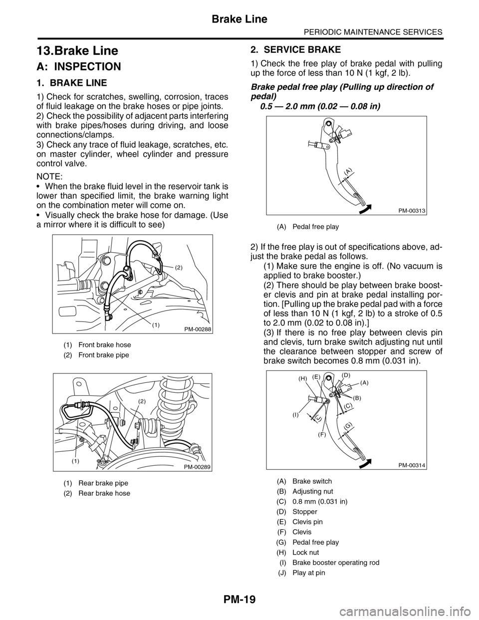
1. BRAKE LINE
1) Check for scratches, swelling, corrosion, traces
of fluid leakage on the brake hoses or pipe joints.
2) Check the possibility of adjacent parts interfering
with brake pipes/hoses during driving, and loose
connections/clamps.
3) Check any trace of fluid leakage, scratches, etc.
on master cylinder, wheel cylinder and pressure
control valve.
NOTE:
•When the brake fluid level in the reservoir tank is
lower than specified limit, the brake warning light
on the combination meter will come on.
•Visually check the brake hose for damage. (Use
a mirror where it is difficult to see)
2. SERVICE BRAKE
1) Check the free play of brake pedal with pulling
up the force of less than 10 N (1 kgf, 2 lb).
Brake pedal free play (Pulling up direction of
pedal)
0.5 — 2.0 mm (0.02 — 0.08 in)
2) If the free play is out of specifications above, ad-
just the brake pedal as follows.
(1) Make sure the engine is off. (No vacuum is
applied to brake booster.)
(2) There should be play between brake boost-
er clevis and pin at brake pedal installing por-
tion. [Pulling up the brake pedal pad with a force
of less than 10 N (1 kgf, 2 lb) to a stroke of 0.5
to 2.0 mm (0.02 to 0.08 in).]
(3) If there is no free play between clevis pin
and clevis, turn brake switch adjusting nut until
the clearance between stopper and screw of
brake switch becomes 0.8 mm (0.031 in).
(1) Front brake hose
(2) Front brake pipe
(1) Rear brake pipe
(2) Rear brake hose
PM-00288
(2)
(1)
PM-00289(1)
(2)
(A) Pedal free play
(A) Brake switch
(B) Adjusting nut
(C) 0.8 mm (0.031 in)
(D) Stopper
(E) Clevis pin
(F) Clevis
(G) Pedal free play
(H) Lock nut
(I) Brake booster operating rod
(J) Play at pin
PM-00313
(A)
PM-00314
(G)
(A)(D)(E)
(B)
(C)
(F)
(J)(I)
(H)