2009 SUBARU TRIBECA Rear diff
[x] Cancel search: Rear diffPage 856 of 2453

FS-8
Wheel Alignment
FRONT SUSPENSION
2. CAMBER
•INSPECTION
1) Place the front wheel on the turning radius
gauge. Make sure the ground contact surfaces of
front and rear wheels are at the same height.
2) Set the adapter at the center of wheel, and then
attach the wheel alignment gauge.
3) Measure the camber angle in accordance with
the operation manual for wheel alignment gauge.
•FRONT CAMBER ADJUSTMENT
1) When adjusting the camber, adjust it to the fol-
lowing value.
2) Loosen the two self–locking nuts located at the
lower front section of the strut.
NOTE:
When the adjusting bolt needs to be loosened or
tightened, hold its head with a wrench and turn the
self–locking nut.
3) Turn the camber adjusting bolt so that the cam-
ber is set at specification.
NOTE:
Moving the adjusting bolt by one scale changes the
camber by approximately 0°15′.
(1) Alignment gauge
(2) Turning radius gauge
(3) Adapter
Camber (Difference between RH and LH 45′ or less)
0°00′±0°45′
Camber (Difference between RH and LH 45′ or less)
0°00′±0°30′
FS-00213
(1)
(2)
(3)
(1) Strut
(2) Adjusting bolt
(3) Housing
(4) Outer
(5) Inner
(6) Camber is increased.
(7) Camber is decreased.
(1)
(4)
(6) (7)
(2)
(3)
(5)
FS-00196
Page 878 of 2453

PB-7
Parking Brake Assembly (Rear Disc Brake)
PARKING BRAKE
4. Parking Brake Assembly
(Rear Disc Brake)
A: REMOVAL
1) Release the parking brake.
2) Lift-up the vehicle, and then remove the rear
wheels.
3) Remove the two mounting bolts and remove the
disc brake caliper assembly.
4) Suspend the rear disk brake caliper assembly so
that the brake hose is not stretched.
5) Remove the rear disk brake rotor.
NOTE:
If the disc rotor is difficult to remove, try the follow-
ing two methods in order.
(1) Turn the adjusting screw using a flat tip
screwdriver until the brake shoe moves ade-
quately away from the disc rotor.
(2) If disc rotor is seized up on the hub, drive the
disc rotor out by pushing two 8-mm bolts in
holes B on the rotor.
6) Remove the shoe return spring.
7) Remove the brake shoe cup and brake shoe
spring, then remove the primary brake shoe.
8) Remove the strut and strut spring.
9) Remove the adjuster assembly.
10) Remove the brake shoe cup and brake shoe
spring, then remove the secondary brake shoe.
(1) Adjuster
(2) Adjusting hole cover (rubber)
(3) Flat tip screwdriver
(4) Disc rotor
PB-00092
(1)
(4)
(2)
(3)
PB-00094(1) Brake shoe cup
(2) Primary brake shoe
B
A
BR-00018
PB-00095
(1)
(2)
PB-00096
Page 935 of 2453

RS-2
General Description
REAR SUSPENSION
1. General Description
A: SPECIFICATION
NOTE:
•Front and rear toe–in and front camber can be
adjusted. Adjust if the toe–in or camber tolerance
exceeds specifications.
•Other items indicated in the specifications table
cannot be adjusted. If other items exceed specifica-
tions, check the suspension parts and connections
for deformation, and replace with new ones as re-
quired.
Wheel arch height
[Tolerance: +12 mm -24 mm ( +0.47 in -0.94 in)]mm (in) 439 (17.3)
Camber
[Tolerance: ±0°45′ Difference between RH and LH 45′ or less]–0°31′
To e – i n m m ( i n ) 2±2 (0.08±0.08) Toe angle (sum of both wheels): 0°9'±0°9'
Thrust angle [Tolerance: ±0°30′]0°
Diameter of stabilizer mm (in) 16 (0.63)
(1) Front
A – B = Positive: Toe-in, Negative: Toe–out
α = Individual toe angles
FS-00001
B
A
(1)
Page 939 of 2453

RS-6
General Description
REAR SUSPENSION
2. GENERAL TOOL
28099PA090 OIL SEAL PROTEC-
TOR
•Used for installing the rear drive shaft to the
rear differential.
•For oil seal protection
TOOL NAME REMARKS
Alignment tester Used for measuring wheel alignment.
To e – i n g a u g e U s e d f o r t o e – i n m e a s u r e m e n t .
Jack Used for removing and installing suspension.
Bearing puller Used for removing bushings.
Coil spring compressor Used for disassembling and assembling shock absorber.
ILLUSTRATION TOOL NUMBER DESCRIPTION REMARKS
ST28099PA090
Page 953 of 2453

TPM(diag)-3
General Description
TIRE PRESSURE MONITORING SYSTEM (DIAGNOSTICS)
2. General Description
A: CAUTION
1. SRS AIRBAG SYSTEM
Airbag system wiring harness is routed near the
TPM control module.
CAUTION:
•Wiring harnesses of all airbag system are yel-
low. Do not use the electrical test equipment on
these circuits.
•Be careful not to damage the airbag system
wiring harness when servicing the tire pressure
monitoring control module.
2. TIRE PRESSURE MONITORING CON-
TROL MODULE
•If the alteration of tire rotation, the installation po-
sition or the replacement of transmitter is per-
formed, ID registration for the transmitter is
required.
Monitor.>
•When adjusting tire pressure indoors in winter,
there is a big temperature difference between the
indoor facilities and outside. Once the car is outside
where the temperature is lower, the air pressure in
the tires will drop, causing the tire pressure warning
light to come on, even if the pressure in the tires
was adjusted to standard values indoors. To avoid
this, it is necessary to adjust the tire pressure to the
high side in consideration of the difference in tem-
perature between inside and outside.
B: INSPECTION
Before performing diagnosis, check the following
item which might affect the quality of the tire pres-
sure monitoring system.
1. TIRE
•Inspect that the tire pressure is within the speci-
fication while the tire is cool. (Refer to Tire Caution
Label.)
•Check the tires for damage or the insertion of for-
eign matters.
2. BATTERY
Check that amount of battery fluid, gravity and volt-
age are within the specifications.
Standard voltage: 12 V or more
Specific gravity: 1.260 or more
Te m p e r a -
ture
°C (°F)
Indoor
tempera-
ture
15.5 (60)
Ambient
tempera-
ture
–1 (30) –12 (10) –23 (–10)
Reference
for adjusting
tire pres-
sure
kPa (psi)
Fr o n t 25 0 ( 36 ) 26 5 ( 3 8 ) 2 8 0 ( 4 0)
Rear 240 (35) 255 (37) 270 (39)
Page 1166 of 2453

EN(H6DO)(diag)-5
General Description
ENGINE (DIAGNOSTICS)
3. General Description
A: CAUTION
1) Airbag system wiring harness is routed near the
ECM, main relay and fuel pump relay.
CAUTION:
•All airbag system wiring harnesses and con-
nectors are colored yellow. Do not use electri-
cal test equipment on these circuits.
•Be careful not to damage the airbag system
wiring harness when servicing the ECM, TCM,
main relay and fuel pump relay.
2) Never connect the battery in reverse polarity.
•The ECM will be destroyed instantly.
•The fuel injector and other parts will be dam-
aged.
3) Do not disconnect the battery terminals while the
engine is running.
A large counter electromotive force will be generat-
ed in the generator, and this voltage may damage
electronic parts such as ECM etc.
4) Before disconnecting the connectors of each
sensor and ECM, be sure to turn the ignition switch
to OFF. Perform the clear memory mode after con-
necting the connectors.
5) Poor contact has been identified as a primary
cause of this problem. Measure the voltage or re-
sistance of individual sensor or all electrical control
modules using a tapered pin with a diameter of less
than 0.64 mm (0.025 in). Do not insert the pin more
than 5 mm (0.20 in) into the part.
6) Remove the ECM from the located position after
disconnecting two cables on battery.
Otherwise, the ECM may be damaged.
CAUTION:
When replacing the ECM, be careful not to use
the wrong spec. ECM to avoid any damage on
the fuel injection system.
7) Connectors of each sensor in the engine com-
partment and the harness connectors on the en-
gine side and body side are all designed to be
waterproof. Even if the connectors are waterproof,
take care not to allow water to get into them when
washing the vehicle, or when servicing the vehicle
in rainy weather.
8) Use ECM mounting stud bolts as the grounding
point to chassis when measuring voltage and resis-
tance in the passenger compartment.
9) Use the engine ground terminal or engine as-
sembly as the grounding point to chassis when
measuring the voltage and resistance in engine
compartment.
10) Every MFI-related part is a precision part. Do
not drop them.
11) Observe the following cautions when installing
a radio in MFI equipped models.
CAUTION:
•The antenna must be kept as far apart as pos-
sible from control unit. (The ECM is located un-
der the steering column, inside of the
instrument panel lower trim panel.)
•The antenna feeder must be placed as far apart
as possible from the ECM and MFI harness.
•Carefully adjust the antenna for correct
matching.
•When mounting a large power type radio, pay
special attention to the three items mentioned
above.
•Incorrect installation of the radio may affect
the operation of ECM.
12) Release the pressure in the fuel system before
disconnecting the fuel hose. If engine starts during
this operation, run it until it stops.
13) For the model with ABS, the ABS warning light
may illuminate when performing driving test with
jacked-up or lifted-up condition, but this is not a
system malfunction. The reason for this is the
speed difference between the front and rear
wheels. After diagnosis of engine control system,
perform the ABS memory clear procedure of self-
diagnosis function.
B: INSPECTION
Before performing diagnostics, check the following
item which might affect engine problems.
1. BATTERY
1) Measure the battery voltage and specific gravity
of electrolyte.
Standard voltage: 12 V
Specific gravity: Above 1.260
2) Check the condition of the main and other fuses,
and harnesses and connectors. Also check for
proper grounding.
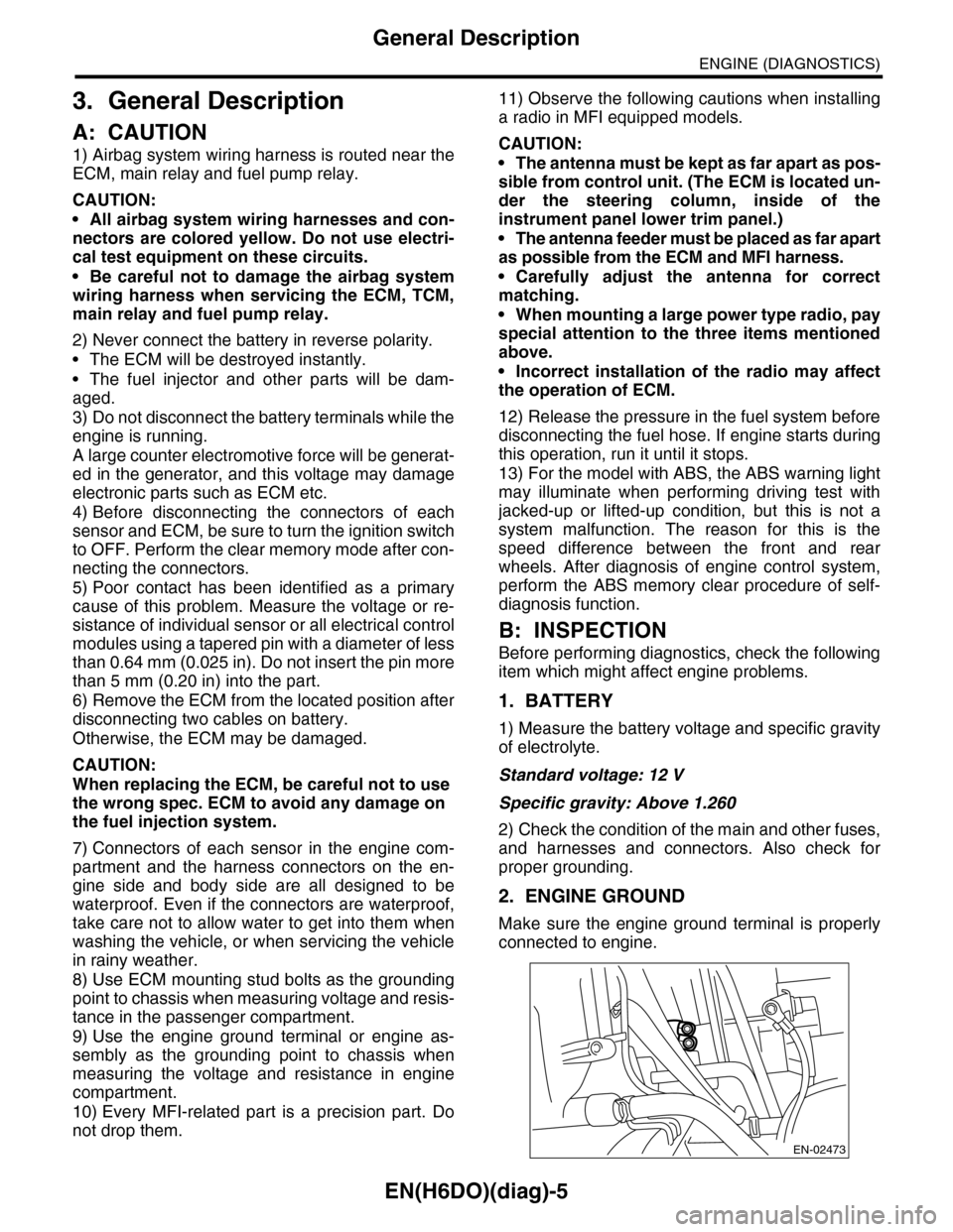
2. ENGINE GROUND
Make sure the engine ground terminal is properly
connected to engine.
EN-02473
Page 1199 of 2453

EN(H6DO)(diag)-38
Inspection Mode
ENGINE (DIAGNOSTICS)
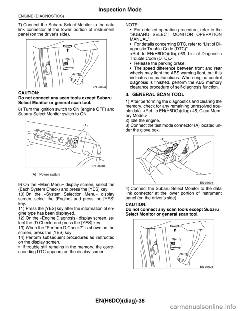
7) Connect the Subaru Select Monitor to the data
link connector at the lower portion of instrument
panel (on the driver's side).
CAUTION:
Do not connect any scan tools except Subaru
Select Monitor or general scan tool.
8) Turn the ignition switch to ON (engine OFF) and
Subaru Select Monitor switch to ON.
9) On the «Main Menu» display screen, select the
{Each System Check} and press the [YES] key.
10) On the «System Selection Menu» display
screen, select the {Engine} and press the [YES]
key.
11) Press the [YES] key after the information of en-
gine type has been displayed.
12) On the «Engine Diagnosis» display screen, se-
lect the {D Check} and press the [YES] key.
13) When the “Perform D Check?” is shown on the
screen, press the [YES] key.
14) Perform subsequent procedures as instructed
on the display screen.
•If trouble still remains in the memory, the corre-
sponding DTC appears on the display screen.
NOTE:
•For detailed operation procedure, refer to the
“SUBARU SELECT MONITOR OPERATION
MANUAL”.
•For details concerning DTC, refer to “List of Di-
agnostic Trouble Code (DTC)”.
•Release the parking brake.
•The speed difference between front and rear
wheels may light the ABS warning light, but this
indicates no malfunctions. When engine control
diagnosis is finished, perform the ABS memory
clearance procedure of self-diagnosis function.
3. GENERAL SCAN TOOL
1) After performing the diagnostics and clearing the
memory, check for any remaining unresolved trou-
ble data.
2) Idle the engine.
3) Connect the test mode connector (A) located un-
der the glove box.
4) Connect the Subaru Select Monitor to the data
link connector at the lower portion of instrument
panel (on the driver’s side).
CAUTION:
Do not connect any scan tools except Subaru
Select Monitor or general scan tool.
(A) Power switch
EN-03693
(A)
EN-00040
EN-03694
(4)
EN-03693
Page 1200 of 2453

EN(H6DO)(diag)-39
Inspection Mode
ENGINE (DIAGNOSTICS)
5) Start the engine.
NOTE:
Make sure the select lever is placed in “P” position
before starting.
6) Using the select lever, turn the “P” position
switch and the “N” position switch to ON.
7) Depress the brake pedal to turn brake switch
ON.
8) Keep the engine speed in 2,500 — 3,000 rpm
range for 40 seconds.
9) Shift the select lever in the “D” range and drive
the vehicle at 5 to 10 km/h (3 to 6 MPH).
NOTE:
•For AWD model, release the parking brake.
•The speed difference between front and rear
wheels may light the ABS warning light, but this in-
dicates no malfunctions. When engine control diag-
nosis is finished, perform the ABS memory
clearance procedure of self-diagnosis system.
10) Using the general scan tool, check DTC and
record the result(s).
NOTE:
•For detailed operation procedure, refer to the
general scan tool operation manual.
•For details concerning DTC, refer to “List of Diag-
nostic Trouble Code (DTC)”.