2009 SUBARU TRIBECA Rear diff
[x] Cancel search: Rear diffPage 2004 of 2453
PM-21
Brake Fluid
PERIODIC MAINTENANCE SERVICES
14.Brake Fluid
A: REPLACEMENT
1) Either jack-up the vehicle and place a rigid rack
under it, or lift-up the vehicle.
2) Remove all the wheels.
3) Drain the brake fluid from master cylinder.
4) Refill the reservoir tank with recommended
brake fluid.
Recommended brake fluid:
Refer to “RM” section.
ed Materials.>
NOTE:
•Avoid mixing different brands of brake fluid to
prevent degrading the quality of fluid.
•Be careful not to allow dirt or dust to get into the
reservoir tank.
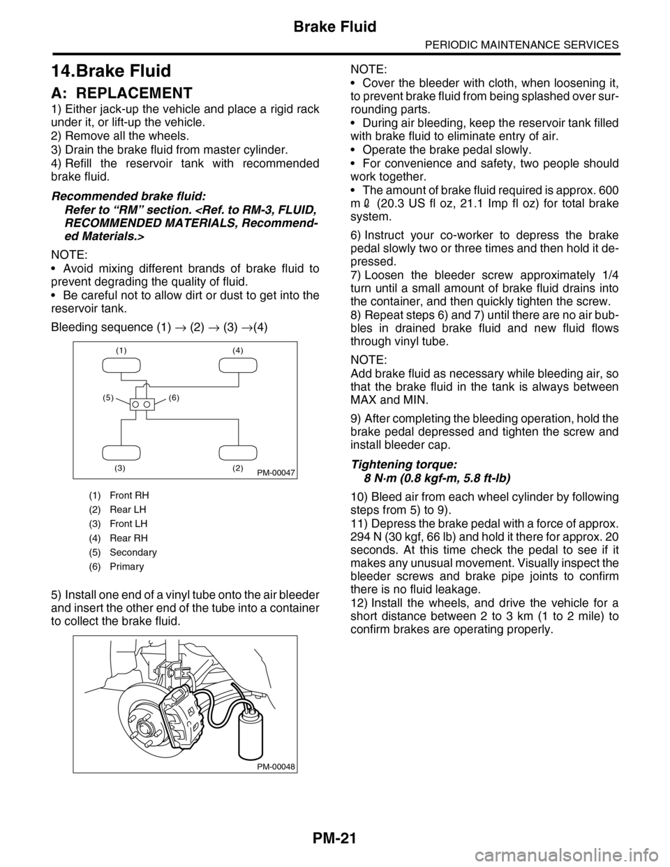
Bleeding sequence (1) → (2) → (3) →(4)
5) Install one end of a vinyl tube onto the air bleeder
and insert the other end of the tube into a container
to collect the brake fluid.
NOTE:
•Cover the bleeder with cloth, when loosening it,
to prevent brake fluid from being splashed over sur-
rounding parts.
•During air bleeding, keep the reservoir tank filled
with brake fluid to eliminate entry of air.
•Operate the brake pedal slowly.
•For convenience and safety, two people should
work together.
•The amount of brake fluid required is approx. 600
m2 (20.3 US fl oz, 21.1 Imp fl oz) for total brake
system.
6) Instruct your co-worker to depress the brake
pedal slowly two or three times and then hold it de-
pressed.
7) Loosen the bleeder screw approximately 1/4
turn until a small amount of brake fluid drains into
the container, and then quickly tighten the screw.
8) Repeat steps 6) and 7) until there are no air bub-
bles in drained brake fluid and new fluid flows
through vinyl tube.
NOTE:
Add brake fluid as necessary while bleeding air, so
that the brake fluid in the tank is always between
MAX and MIN.
9) After completing the bleeding operation, hold the
brake pedal depressed and tighten the screw and
install bleeder cap.
Tightening torque:
8 N·m (0.8 kgf-m, 5.8 ft-lb)
10) Bleed air from each wheel cylinder by following
steps from 5) to 9).
11) Depress the brake pedal with a force of approx.
294 N (30 kgf, 66 lb) and hold it there for approx. 20
seconds. At this time check the pedal to see if it
makes any unusual movement. Visually inspect the
bleeder screws and brake pipe joints to confirm
there is no fluid leakage.
12) Install the wheels, and drive the vehicle for a
short distance between 2 to 3 km (1 to 2 mile) to
confirm brakes are operating properly.
(1) Front RH
(2) Rear LH
(3) Front LH
(4) Rear RH
(5) Secondary
(6) Primary
(1) (4)
(2)(3)
(5) (6)
PM-00047
PM-00048
Page 2046 of 2453
5AT-30
Stall Test
AUTOMATIC TRANSMISSION
5. Stall Test
A: INSPECTION
NOTE:
The stall test is extremely important in diagnosing
the condition of an automatic transmission and en-
gine. It should be conducted to measure the engine
stall speeds in “R” and “2nd of manual mode”.
Purposes of the stall test:
•Operational check of the automatic transmission
clutch
•Operational check of the torque converter clutch
•Engine performance check
1) Check that the throttle valve fully opens.
2) Check that the engine oil level is correct.
3) Check that the coolant level is correct.
4) Check that the ATF level is correct.
5) Check that the differential gear oil level is cor-
rect.
6) Raise the ATF temperature to 70 to 80°C (158 to
176°F) by driving a distance of 5 to 10 km (3 to 6
miles). Confirm the ATF temperature on Subaru
Select Monitor.
tor.>
7) Place the wheel chocks at the front and rear of
all wheels and apply the parking brake.
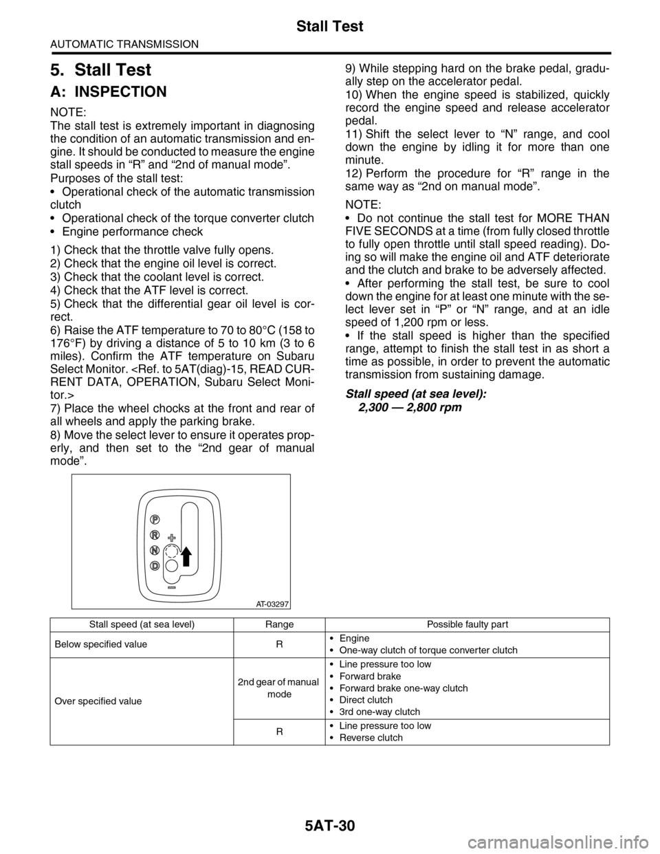
8) Move the select lever to ensure it operates prop-
erly, and then set to the “2nd gear of manual
mode”.
9) While stepping hard on the brake pedal, gradu-
ally step on the accelerator pedal.
10) When the engine speed is stabilized, quickly
record the engine speed and release accelerator
pedal.
11) Shift the select lever to “N” range, and cool
down the engine by idling it for more than one
minute.
12) Perform the procedure for “R” range in the
same way as “2nd on manual mode”.
NOTE:
•Do not continue the stall test for MORE THAN
FIVE SECONDS at a time (from fully closed throttle
to fully open throttle until stall speed reading). Do-
ing so will make the engine oil and ATF deteriorate
and the clutch and brake to be adversely affected.
•After performing the stall test, be sure to cool
down the engine for at least one minute with the se-
lect lever set in “P” or “N” range, and at an idle
speed of 1,200 rpm or less.
•If the stall speed is higher than the specified
range, attempt to finish the stall test in as short a
time as possible, in order to prevent the automatic
transmission from sustaining damage.
Stall speed (at sea level):
2,300 — 2,800 rpm
AT-03297
Stall speed (at sea level) Range Possible faulty part
Below specified value R•Engine
•One-way clutch of torque converter clutch
Over specified value
2nd gear of manual
mode
•Line pressure too low
•Forward brake
•Forward brake one-way clutch
•Direct clutch
•3rd one-way clutch
R•Line pressure too low
•Reverse clutch
Page 2063 of 2453
5AT-47
Front Vehicle Speed Sensor
AUTOMATIC TRANSMISSION
14.Front Vehicle Speed Sensor
A: REMOVAL
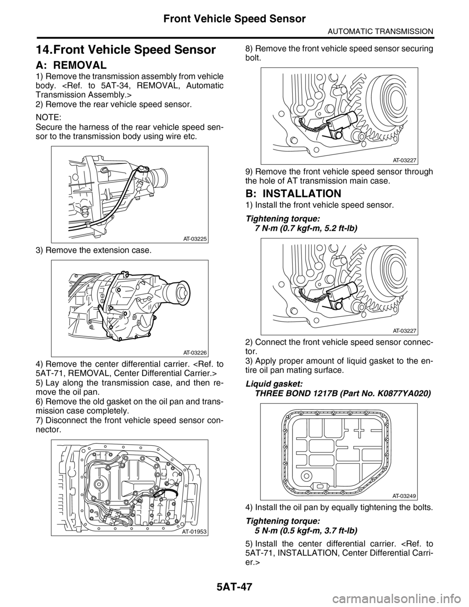
1) Remove the transmission assembly from vehicle
body.
2) Remove the rear vehicle speed sensor.
NOTE:
Secure the harness of the rear vehicle speed sen-
sor to the transmission body using wire etc.
3) Remove the extension case.
4) Remove the center differential carrier.
5) Lay along the transmission case, and then re-
move the oil pan.
6) Remove the old gasket on the oil pan and trans-
mission case completely.
7) Disconnect the front vehicle speed sensor con-
nector.
8) Remove the front vehicle speed sensor securing
bolt.
9) Remove the front vehicle speed sensor through
the hole of AT transmission main case.
B: INSTALLATION
1) Install the front vehicle speed sensor.
Tightening torque:
7 N·m (0.7 kgf-m, 5.2 ft-lb)
2) Connect the front vehicle speed sensor connec-
tor.
3) Apply proper amount of liquid gasket to the en-
tire oil pan mating surface.
Liquid gasket:
THREE BOND 1217B (Part No. K0877YA020)
4) Install the oil pan by equally tightening the bolts.
Tightening torque:
5 N·m (0.5 kgf-m, 3.7 ft-lb)
5) Install the center differential carrier.
er.>
AT-03225
AT-03226
AT-01953
AT-03227
AT-03227
AT-03249
Page 2081 of 2453
5AT-65
Transfer Clutch
AUTOMATIC TRANSMISSION
25.Transfer Clutch
A: REMOVAL
1) Remove the transmission assembly from vehicle
body.
2) Remove the extension case, and then remove
the transfer clutch.
B: INSTALLATION
1) Select the rear drive shaft shim.
2) Select driven plate No. 3.
3) Install the extension case.
4) Install the transmission assembly to the vehicle.
C: INSPECTION
•Inspect the drive plate facing for wear and dam-
age.
•Make sure the snap ring is not worn and the re-
turn spring has no permanent distortion, damage,
or deformation.
•Check that the D-ring is not damaged.
•Inspect the extension end play, and adjust it to
within the standard value.
D: ADJUSTMENT
1. REAR DRIVE SHAFT SHIM SELECTION
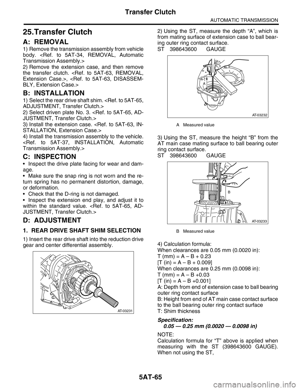
1) Insert the rear drive shaft into the reduction drive
gear and center differential assembly.
2) Using the ST, measure the depth “A”, which is
from mating surface of extension case to ball bear-
ing outer ring contact surface.
ST 398643600 GAUGE
3) Using the ST, measure the height “B” from the
AT main case mating surface to ball bearing outer
ring contact surface.
ST 398643600 GAUGE
4) Calculation formula:
When clearances are 0.05 mm (0.0020 in):
T (mm) = A – B + 0.23
[T (in) = A – B + 0.009]
When clearances are 0.25 mm (0.0098 in):
T (mm) = A – B +0.03
[T (in) = A – B +0.001]
A: Depth from end of extension case to ball bearing
outer ring contact surface
B: Height from end of AT main case contact surface
to the ball bearing outer ring contact surface
T: Shim thickness
Specification:
0.05 — 0.25 mm (0.0020 — 0.0098 in)
NOTE:
Calculation formula for “T” above is applied when
measuring with the ST (398643600 GAUGE).
When not using the ST,
AT-03231
AMeasured value
BMeasured value
AT-03232
A
AT-03233
B
Page 2083 of 2453
5AT-67
Rear Drive Shaft
AUTOMATIC TRANSMISSION
26.Rear Drive Shaft
A: REMOVAL
1) Remove the transmission assembly from vehicle
body.
2) Remove the rear vehicle speed sensor, and then
remove the extension case.
3) Pull out the rear driveshaft from center differen-
tial assembly.
4) Remove the drive plate and driven plate.
B: INSTALLATION
1) Select the shim.
2) Install drive plate and driven plate.
3) Insert the rear driveshaft into the center differen-
tial assembly.
4) Combine the extension case, and then install the
rear vehicle speed sensor.
5) Install the transmission assembly to the vehicle.
C: DISASSEMBLY
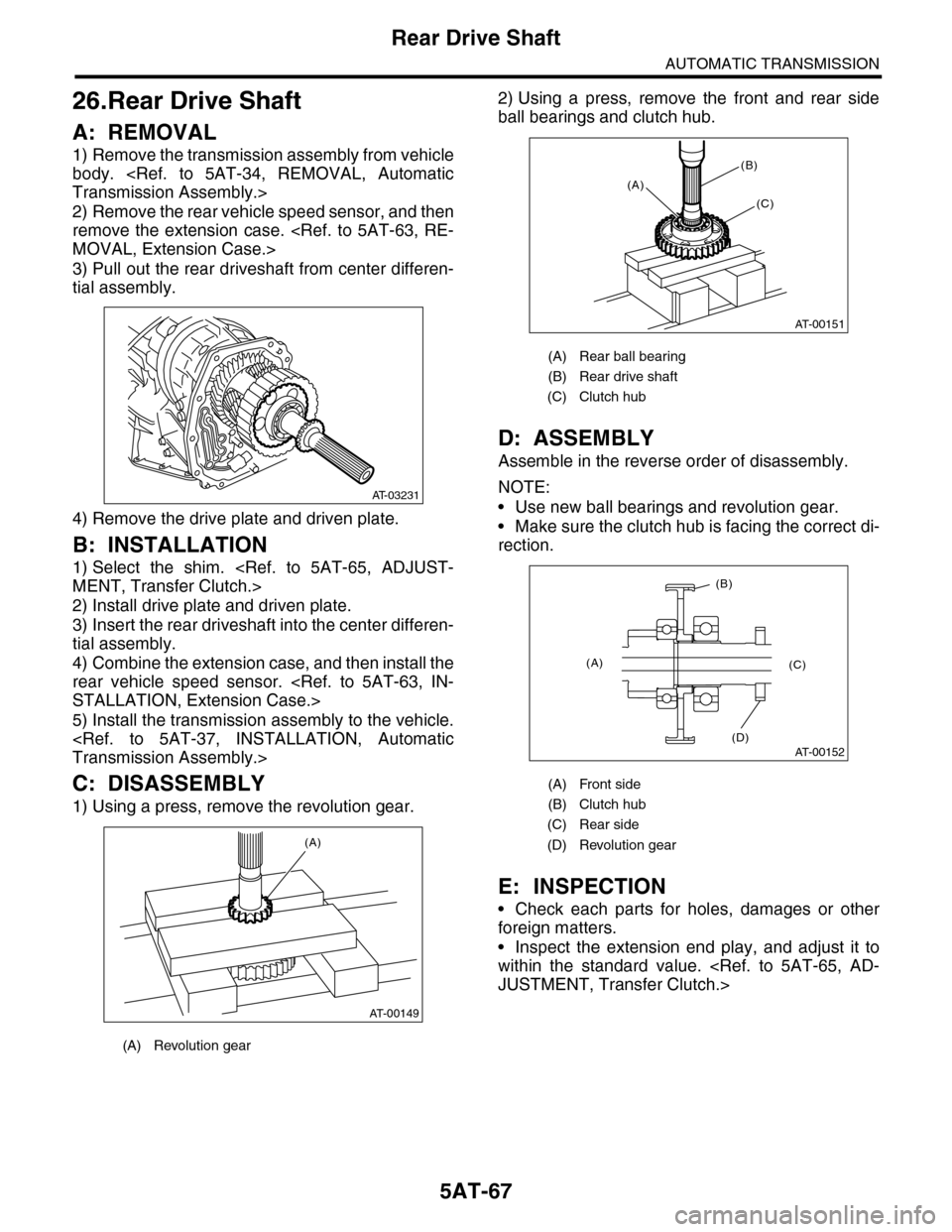
1) Using a press, remove the revolution gear.
2) Using a press, remove the front and rear side
ball bearings and clutch hub.
D: ASSEMBLY
Assemble in the reverse order of disassembly.
NOTE:
•Use new ball bearings and revolution gear.
•Make sure the clutch hub is facing the correct di-
rection.
E: INSPECTION
•Check each parts for holes, damages or other
foreign matters.
•Inspect the extension end play, and adjust it to
within the standard value.
(A) Revolution gear
AT-03231
AT-00149
(A)
(A) Rear ball bearing
(B) Rear drive shaft
(C) Clutch hub
(A) Front side
(B) Clutch hub
(C) Rear side
(D) Revolution gear
AT-00151
(A)
(B)
(C)
AT-00152
(A)
(B)
(C)
(D)
Page 2084 of 2453
5AT-68
Reduction Driven Gear
AUTOMATIC TRANSMISSION
27.Reduction Driven Gear
A: REMOVAL
1) Remove the transmission assembly from vehicle
body.
2) Remove the rear wheel speed sensor, and sep-
arate the extension case from transmission case.
3) Remove the center differential carrier.
4) Set the range select lever to the “P” range.
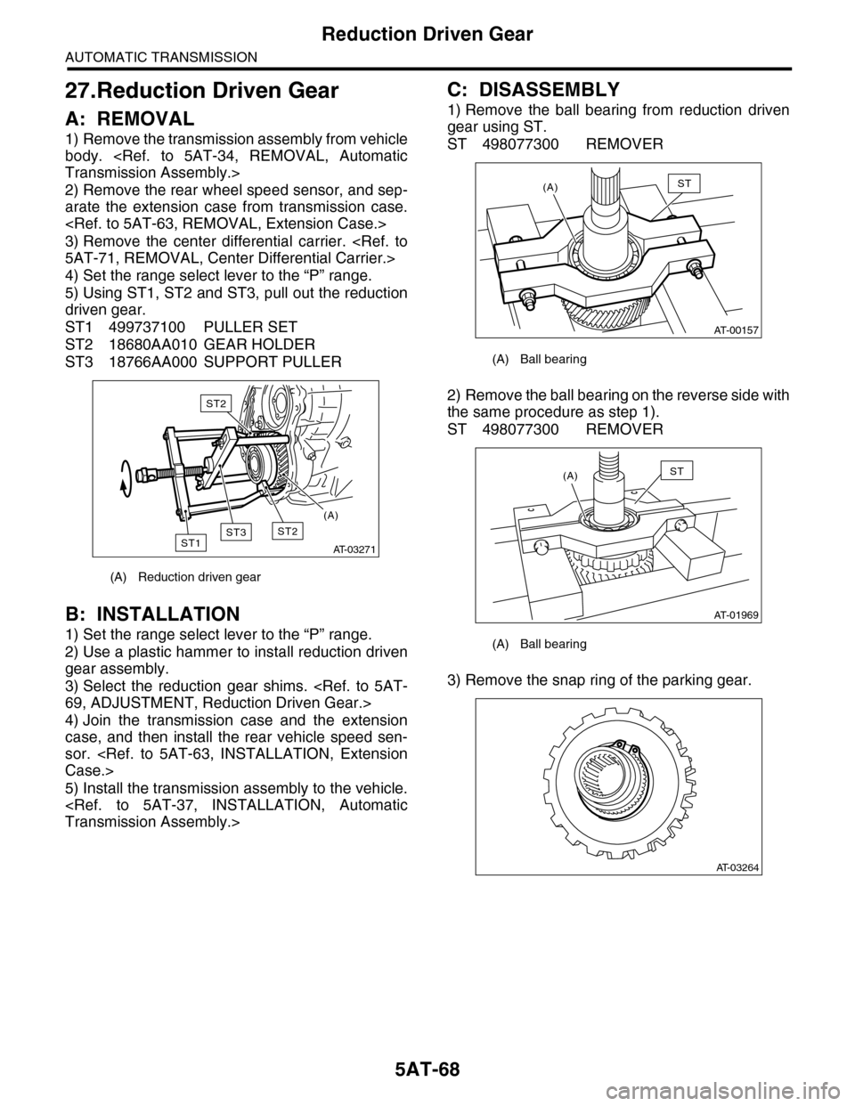
5) Using ST1, ST2 and ST3, pull out the reduction
driven gear.
ST1 499737100 PULLER SET
ST2 18680AA010 GEAR HOLDER
ST3 18766AA000 SUPPORT PULLER
B: INSTALLATION
1) Set the range select lever to the “P” range.
2) Use a plastic hammer to install reduction driven
gear assembly.
3) Select the reduction gear shims.
4) Join the transmission case and the extension
case, and then install the rear vehicle speed sen-
sor.
5) Install the transmission assembly to the vehicle.
C: DISASSEMBLY
1) Remove the ball bearing from reduction driven
gear using ST.
ST 498077300 REMOVER
2) Remove the ball bearing on the reverse side with
the same procedure as step 1).
ST 498077300 REMOVER
3) Remove the snap ring of the parking gear.
(A) Reduction driven gear
AT-03271
ST2ST1
ST2
ST3
(A)
(A) Ball bearing
(A) Ball bearing
AT-00157
(A)ST
AT-01969
(A)ST
AT-03264
Page 2087 of 2453
5AT-71
Center Differential Carrier
AUTOMATIC TRANSMISSION
28.Center Differential Carrier
A: REMOVAL
1) Remove the transmission assembly from vehicle
body.
2) Remove the rear wheel speed sensor, and sep-
arate the extension case from transmission case.
3) Extract the rear drive shaft.
4) Pull out the center differential carrier assembly.
5) Pull out the shim(s) from transmission case.
B: INSTALLATION
1) Install the center differential assembly with the
shim(s).
NOTE:
Press-fit it to the bottom of bearing shoulder com-
pletely.
2) Insert the rear driveshaft assembly.
3) Join the transmission case and the extension
case, and then install the rear vehicle speed sen-
sor.
4) Install the transmission assembly to the vehicle.
C: DISASSEMBLY
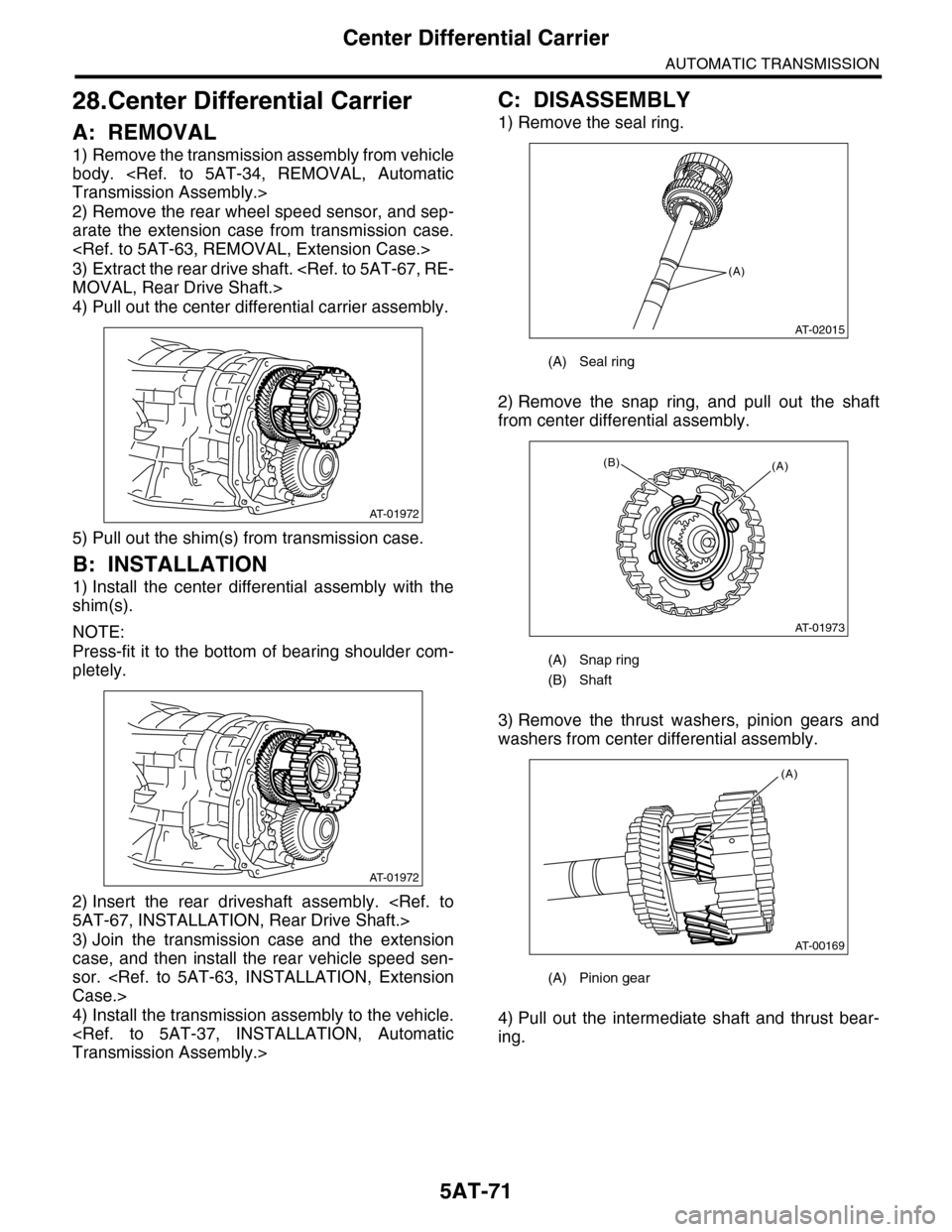
1) Remove the seal ring.
2) Remove the snap ring, and pull out the shaft
from center differential assembly.
3) Remove the thrust washers, pinion gears and
washers from center differential assembly.
4) Pull out the intermediate shaft and thrust bear-
ing.
AT-01972
AT-01972
(A) Seal ring
(A) Snap ring
(B) Shaft
(A) Pinion gear
(A)
AT-02015
AT-01973
(A)(B)
AT-00169
(A)
Page 2097 of 2453
5AT-81
Drive Pinion Shaft Assembly
AUTOMATIC TRANSMISSION
32.Drive Pinion Shaft Assembly
A: REMOVAL
1) Remove the transmission assembly from vehicle
body.
2) Pull out the torque converter assembly.
3) Remove the transmission harness connector
from stay.
4) Disconnect the air breather hose.
5) Remove the oil charge pipe.
6) Remove the ATF filter inlet and outlet pipes.
7) Separate the converter case and transmission
case.
8) Remove the drive pinion shaft mounting bolts,
and then remove the drive pinion shaft assembly
from oil pump cover.
9) Remove the oil pump cover from AT main case.
B: INSTALLATION
1) Assemble the drive pinion assembly to oil pump
cover.
NOTE:
Be careful not to bend the shim.
Tightening torque:
70 N·m (7.1 kgf-m, 51.6 ft-lb)
2) Adjust the tooth contact between drive pinion
shaft assembly and the front differential side gear.
3) Join the converter case with the transmission
case.
4) Install the transmission harness connector to the
stay.
5) Install the ATF filter pipe.
6) Install the oil charge pipe with O-ring.
7) Install the torque converter assembly.
sembly.>
8) Install the transmission assembly to the vehicle.
C: DISASSEMBLY
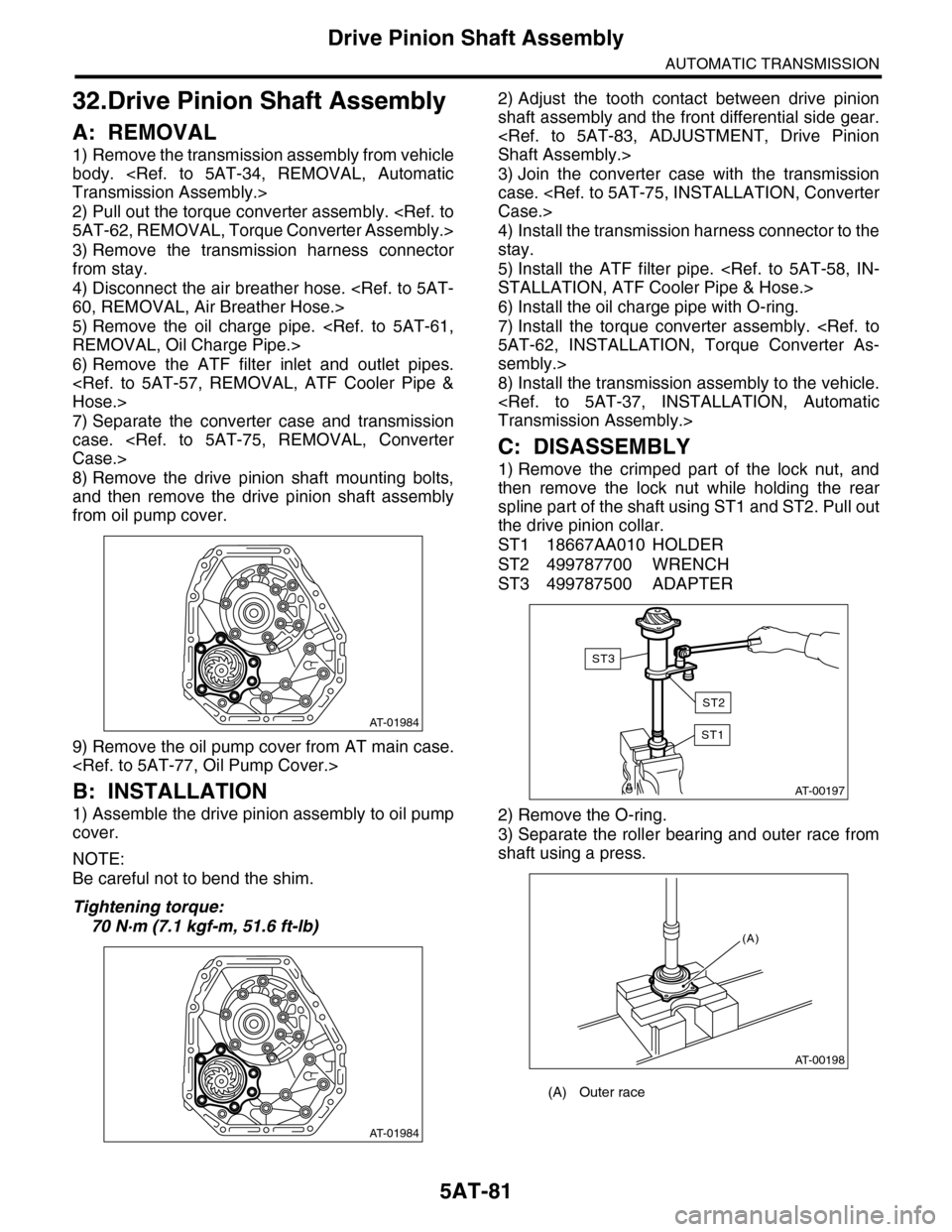
1) Remove the crimped part of the lock nut, and
then remove the lock nut while holding the rear
spline part of the shaft using ST1 and ST2. Pull out
the drive pinion collar.
ST1 18667AA010 HOLDER
ST2 499787700 WRENCH
ST3 499787500 ADAPTER
2) Remove the O-ring.
3) Separate the roller bearing and outer race from
shaft using a press.
AT-01984
AT-01984
(A) Outer race
AT-00197
ST1
ST3
ST2
AT-00198
(A)