Page 2291 of 2453

WI-7
Basic Diagnostic Procedure
WIRING SYSTEM
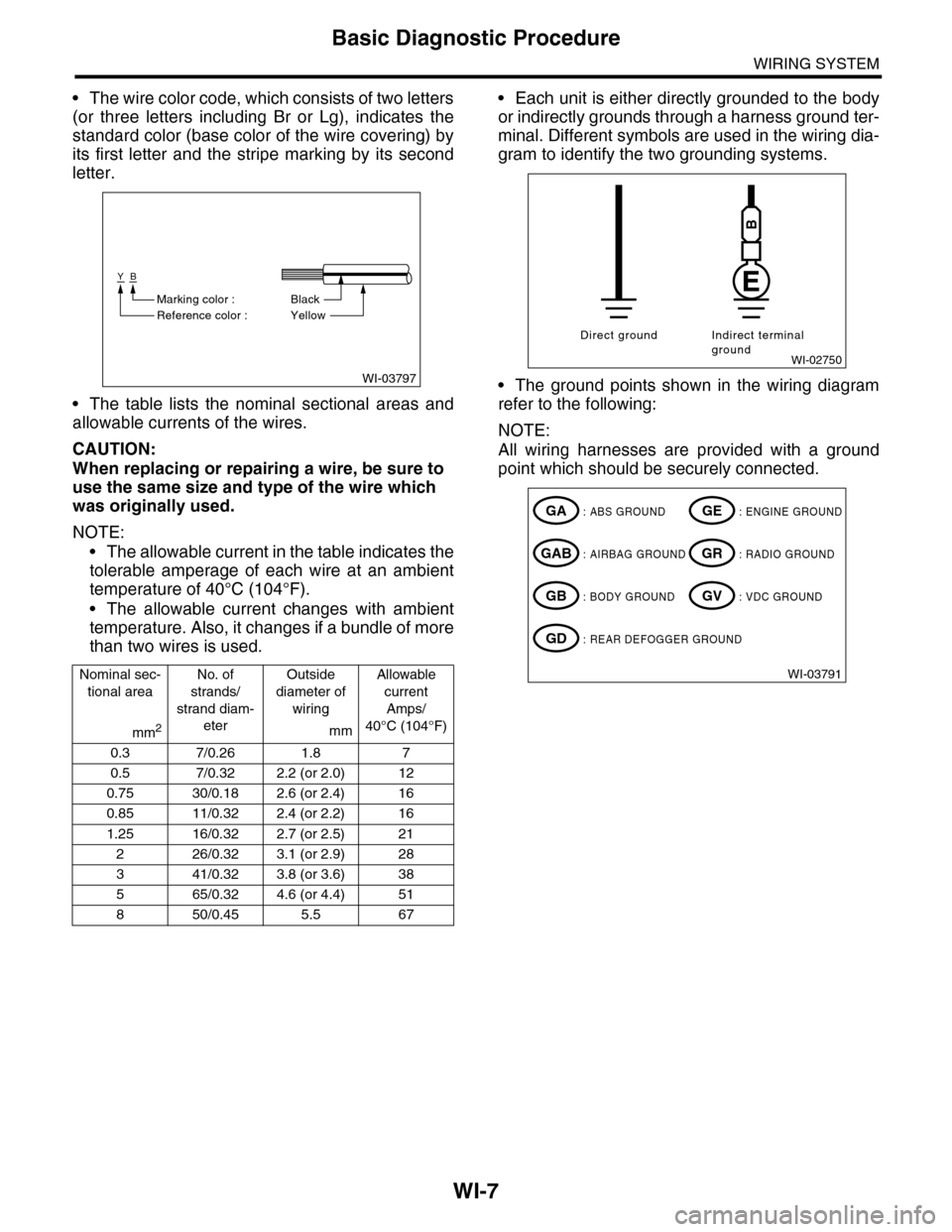
•The wire color code, which consists of two letters
(or three letters including Br or Lg), indicates the
standard color (base color of the wire covering) by
its first letter and the stripe marking by its second
letter.
•The table lists the nominal sectional areas and
allowable currents of the wires.
CAUTION:
When replacing or repairing a wire, be sure to
use the same size and type of the wire which
was originally used.
NOTE:
•The allowable current in the table indicates the
tolerable amperage of each wire at an ambient
temperature of 40°C (104°F).
•The allowable current changes with ambient
temperature. Also, it changes if a bundle of more
than two wires is used.
•Each unit is either directly grounded to the body
or indirectly grounds through a harness ground ter-
minal. Different symbols are used in the wiring dia-
gram to identify the two grounding systems.
•The ground points shown in the wiring diagram
refer to the following:
NOTE:
All wiring harnesses are provided with a ground
point which should be securely connected.
Nominal sec-
tional area
No. of
strands/
strand diam-
eter
Outside
diameter of
wiring
Allowable
current
Amps/
40°C (104°F)mm2mm
0.3 7/0.26 1.8 7
0.5 7/0.32 2.2 (or 2.0) 12
0.75 30/0.18 2.6 (or 2.4) 16
0.85 11/0.32 2.4 (or 2.2) 16
1.25 16/0.32 2.7 (or 2.5) 21
226/0.323.1 (or 2.9)28
341/0.323.8 (or 3.6)38
565/0.324.6 (or 4.4)51
850/0.455.5 67
WI-03797
YB
BlackMarking color :
Reference color : Yellow
WI-02750
Direct ground Indirect terminalground
B
WI-03791
: ABS GROUNDGA
: AIRBAG GROUNDGAB
: BODY GROUNDGB
: ENGINE GROUNDGE
: RADIO GROUNDGR
: VDC GROUNDGV
: REAR DEFOGGER GROUNDGD
Page 2416 of 2453
WI-132
Combination Meter System
WIRING SYSTEM
WI-08134
METER-02METER-02
ECM
TPM
CONTROL M
ODULE
VDC CONTROL M
ODULE
OIL P
RESSURE SW
ITCH
GENERATOR
BRAKE FLU
ID LEV
EL SWITCH
AIRBAG WARNING LIGHT
HEADLIGHT RELAYAIRBAG CONTROLMODULE
ABS WARNING LIGHT
CHARGE WARNING LIGHTPARKING BRAKE/BRAKE FLUIDLEVEL WARNING LIGHT
VDC CONTROL M
ODULE
PARKING BRAKE SWITCH
REAR DIFFE
RENTIAL
PRESSURE SWITCH
SEA
T BELT W
ARNING LIG
HT
SEAT BELT S
WITCH
A3
IGNITION SWITCH (IG)
A4
REVERSECIRCUIT
OIL PRESSUREWARNING LIGHT
MALFUNCTION INDICATOR LIGHT
HI-BEAM INDICATOR LIGHT
TURN SIGNAL &HAZARD MODULE
TURN SIGNALINDICATOR LIGHT LHTURN SIGNALINDICATOR LIGHT RH
REVERSECIRCUIT
REVERSECIRCUIT
B
B3A14B1B12
METER-03A
BATTERY
B8B7B9B6B10B5B4B11
REAR DIFFERENTIAL OIL TEMPERATURE WARNING LIGHT
REVERSECIRCUIT
DIMMER SWITCH
TIRE INFLATION PRESSURE WARNING LIGHT
REVERSECIRCUIT
A10A7
Page 2432 of 2453
WI-148
Rear Differential Oil Temperature Warning Light System
WIRING SYSTEM
53.Rear Differential Oil Temperature Warning Light System
A: WIRING DIAGRAM
WI-08322
D/T-01D/T-01
48
i53
R98
R15
R60
1
Y
Y
YB
B
B
Y
Y
YBYBY
REARDIFFERENTIALOIL TEMPERATUREWARNING LIGHT
R234R277
REAR DIFFERENTIAL OILTEMPERATURE SWITCH
REAR DIFFERENTIAL
STAYGROUND
i10
19 20 2115 16 17 182223242526272829301234568910 11 12 13 147
A:R60
12
10115634897131412
123 8910411 12 13 14 15 16567171819202122
i53(BLUE)
123456789101112
i126(BLACK)
i127(BLACK)
: TERMINAL NO. OPTIONAL ARRANGEMENT BETWEEN 5 AND 6
1*
: TERMINAL NO. OPTIONAL ARRANGEMENT AMONG 7, 8 AND 9
2*
: TERMINAL NO. OPTIONAL ARRANGEMENT AMONG 10, 11 AND 12
3*COMBINATION METER
A: i10
I/F
I/F
MICRO COMPUTERDRIVER
A15A7A16
A3A4
BrW
BrW
BrW
BrW
JOINTCONNECTOR
i126
i127
3*
2*2*
BY
REF. TO GROUNDCIRCUIT [GND-05]
B
REF. TO GROUNDCIRCUIT [GND-05]
FB-36F/B FUSE NO. 5(IG)
TO POWER SUPPLY CIRCUIT
Page 2445 of 2453

WI-161
Rear Wiring Harness
WIRING SYSTEM
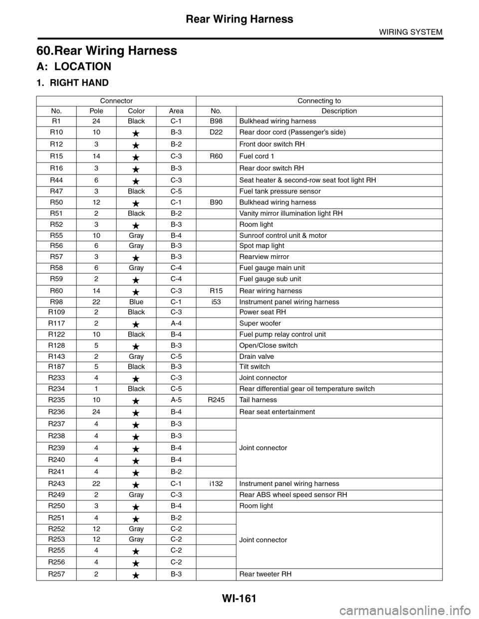
60.Rear Wiring Harness
A: LOCATION
1. RIGHT HAND
Connector Connecting to
No. Pole Color Area No. Description
R1 24 Black C-1 B98 Bulkhead wiring harness
R10 10 B-3 D22 Rear door cord (Passenger’s side)
R12 3 B-2 Front door switch RH
R15 14 C-3 R60 Fuel cord 1
R16 3 B-3 Rear door switch RH
R44 6 C-3 Seat heater & second-row seat foot light RH
R47 3 Black C-5 Fuel tank pressure sensor
R50 12 C-1 B90 Bulkhead wiring harness
R51 2 Black B-2 Vanity mirror illumination light RH
R52 3 B-3 Room light
R55 10 Gray B-4 Sunroof control unit & motor
R56 6 Gray B-3 Spot map light
R57 3 B-3 Rearview mirror
R58 6 Gray C-4 Fuel gauge main unit
R59 2 C-4 Fuel gauge sub unit
R60 14 C-3 R15 Rear wiring harness
R98 22 Blue C-1 i53 Instrument panel wiring harness
R109 2 Black C-3 Power seat RH
R117 2 A-4 Super woofer
R122 10 Black B-4 Fuel pump relay control unit
R128 5 B-3 Open/Close switch
R143 2 Gray C-5 Drain valve
R187 5 Black B-3 Tilt switch
R233 4 C-3 Joint connector
R234 1 Black C-5 Rear differential gear oil temperature switch
R235 10 A-5 R245 Tail harness
R236 24 B-4 Rear seat entertainment
R237 4 B-3
Joint connector
R238 4 B-3
R239 4 B-4
R240 4 B-4
R241 4 B-2
R243 22 C-1 i132 Instrument panel wiring harness
R249 2 Gray C-3 Rear ABS wheel speed sensor RH
R250 3 B-4 Room light
R251 4 B-2
Joint connector
R252 12 Gray C-2
R253 12 Gray C-2
R255 4 C-2
R256 4 C-2
R257 2 B-3 Rear tweeter RH
Page 2446 of 2453
WI-162
Rear Wiring Harness
WIRING SYSTEM
R270 2 Black B-4 Home link
R277 1 Black C-5 Bracket earth (Rear differential gear oil temperature switch)
Connector Connecting to
No. Pole Color Area No. Description
AB18 20 Yellow D-3 Airbag control module
AB24 2 Yellow C-3 Inflator (Side) RH
AB26 2 Black B-2 Pretensioner RH
AB28 4 Yellow B-2 Side airbag sensor RH
AB33 2 Yellow A-4 Inflator (Curtain) RH
AB34 4 Yellow B-3 Curtain airbag sensor RH
AB56 3 Brown C-2 Belt tensioner sensor
AB57 2 Yellow C-1 AB55 Bulkhead harness
AB61 6 Gray C-2 AB59 Occupant detection control module
: White or natural color
Connector Connecting to
No. Pole Color Area No. Description