Page 1765 of 2453
GD(H6DO)-153
Diagnostic Trouble Code (DTC) Detecting Criteria
GENERAL DESCRIPTION
CN:DTC P0462 FUEL LEVEL SENSOR CIRCUIT LOW INPUT
1. OUTLINE OF DIAGNOSIS
Detect the open or short circuit of fuel level sensor. Judge as NG if it is out of specification.
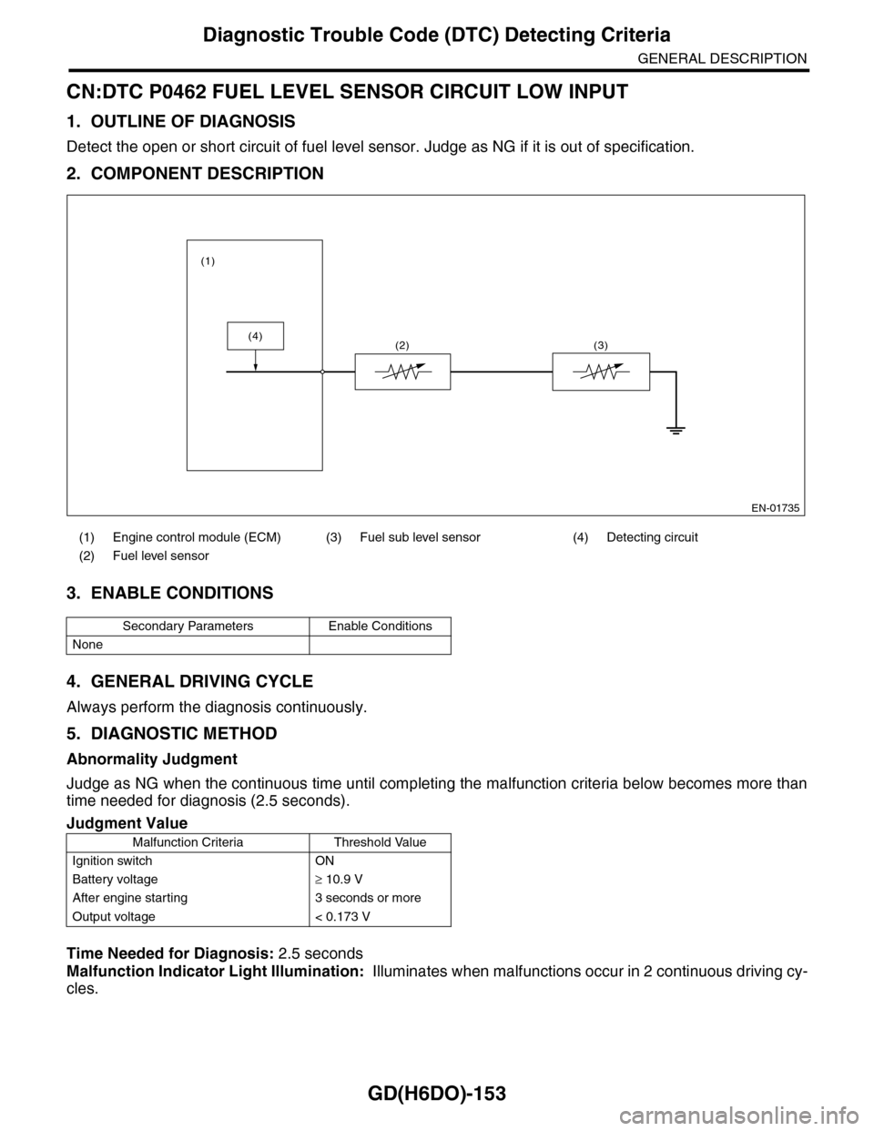
2. COMPONENT DESCRIPTION
3. ENABLE CONDITIONS
4. GENERAL DRIVING CYCLE
Always perform the diagnosis continuously.
5. DIAGNOSTIC METHOD
Abnormality Judgment
Judge as NG when the continuous time until completing the malfunction criteria below becomes more than
time needed for diagnosis (2.5 seconds).
Time Needed for Diagnosis: 2.5 seconds
Malfunction Indicator Light Illumination: Illuminates when malfunctions occur in 2 continuous driving cy-
cles.
(1) Engine control module (ECM) (3) Fuel sub level sensor (4) Detecting circuit
(2) Fuel level sensor
Secondary Parameters Enable Conditions
None
Judgment Value
Malfunction Criteria Threshold Value
Ignition switch ON
Battery voltage≥ 10.9 V
After engine starting 3 seconds or more
Output voltage < 0.173 V
EN-01735
(4)
(1)
(2) (3)
Page 1767 of 2453
GD(H6DO)-155
Diagnostic Trouble Code (DTC) Detecting Criteria
GENERAL DESCRIPTION
CO:DTC P0463 FUEL LEVEL SENSOR CIRCUIT HIGH INPUT
1. OUTLINE OF DIAGNOSIS
Detect the open or short circuit of fuel level sensor. Judge as NG if it is out of specification.
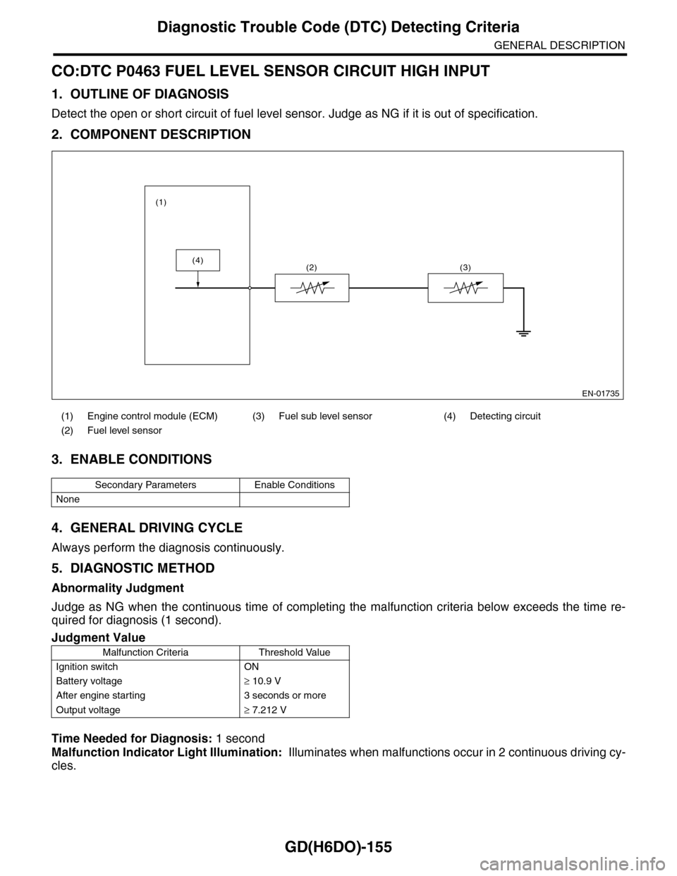
2. COMPONENT DESCRIPTION
3. ENABLE CONDITIONS
4. GENERAL DRIVING CYCLE
Always perform the diagnosis continuously.
5. DIAGNOSTIC METHOD
Abnormality Judgment
Judge as NG when the continuous time of completing the malfunction criteria below exceeds the time re-
quired for diagnosis (1 second).
Time Needed for Diagnosis: 1 second
Malfunction Indicator Light Illumination: Illuminates when malfunctions occur in 2 continuous driving cy-
cles.
(1) Engine control module (ECM) (3) Fuel sub level sensor (4) Detecting circuit
(2) Fuel level sensor
Secondary Parameters Enable Conditions
None
Judgment Value
Malfunction Criteria Threshold Value
Ignition switch ON
Battery voltage≥ 10.9 V
After engine starting 3 seconds or more
Output voltage≥ 7.212 V
EN-01735
(4)
(1)
(2) (3)
Page 1769 of 2453
GD(H6DO)-157
Diagnostic Trouble Code (DTC) Detecting Criteria
GENERAL DESCRIPTION
CP:DTC P0464 FUEL LEVEL SENSOR CIRCUIT INTERMITTENT
1. OUTLINE OF DIAGNOSIS
Detect the unstable output faults from the fuel level sensor caused by noise. Judge as NG when the max. val-
ue and cumulative value of output voltage variation of the fuel level sensor is larger than the threshold value.
2. ENABLE CONDITIONS
3. GENERAL DRIVING CYCLE
•Always perform the diagnosis continuously at idle speed.
•Pay attention to the fuel level.
Malfunction Criteria Threshold Value
Engine speed≥ 500 rpm
After engine starting 1 second or more
Ignition switch ON
Battery voltage > 10.9 V
Idle switch ON
Fuel level 9.6 ←→ 54.4 2 (2.54
←→ 14.37 US gal,
2.11 ←→ 11.97 Imp
gal)
Ve h i c l e s p e e d = 0 k m / h ( 0 M P H ) 1 0 s e c o n d s o r m o r e
Page 1770 of 2453
GD(H6DO)-158
Diagnostic Trouble Code (DTC) Detecting Criteria
GENERAL DESCRIPTION
4. DIAGNOSTIC METHOD
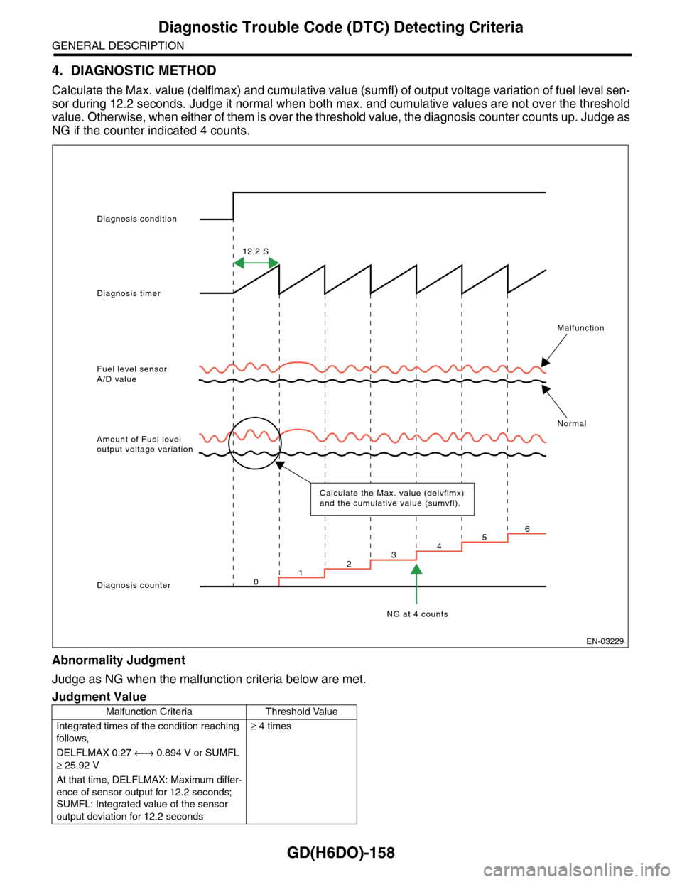
Calculate the Max. value (delflmax) and cumulative value (sumfl) of output voltage variation of fuel level sen-
sor during 12.2 seconds. Judge it normal when both max. and cumulative values are not over the threshold
value. Otherwise, when either of them is over the threshold value, the diagnosis counter counts up. Judge as
NG if the counter indicated 4 counts.
Abnormality Judgment
Judge as NG when the malfunction criteria below are met.
Judgment Value
Malfunction Criteria Threshold Value
Integrated times of the condition reaching
follows,
≥ 4 times
DELFLMAX 0.27 ←→ 0.894 V or SUMFL
≥ 25.92 V
At that time, DELFLMAX: Maximum differ-
ence of sensor output for 12.2 seconds;
SUMFL: Integrated value of the sensor
output deviation for 12.2 seconds
Diagnosis condition
Diagnosis timer
12.2 S
Fuel level sensorA/D value
Malfunction
Normal
Amount of Fuel leveloutput voltage variation
Diagnosis counter
NG at 4 counts
Calculate the Max. value (delvflmx) and the cumulative value (sumvfl).
123456
0
EN-03229
Page 1771 of 2453
GD(H6DO)-159
Diagnostic Trouble Code (DTC) Detecting Criteria
GENERAL DESCRIPTION
The diagnosis counter does not count up when the following conditions are completed within 12.2 seconds.
Time Needed for Diagnosis: 12.2 seconds × 4 times
Malfunction Indicator Light Illumination: Illuminates when malfunctions occur in 2 continuous driving cy-
cles.
Normality Judgment
Judge as OK and clear the NG when the malfunction criteria below are met.
5. DTC CLEAR CONDITION
•When the OK idling cycle is completed 40 times in a row
•When “Clear Memory” is performed
6. MALFUNCTION INDICATOR LIGHT CLEAR CONDITIONS
•When the OK driving cycle is completed 3 times in a row
•When “Clear Memory” is performed
7. FAIL SAFE
None
8. ECM OPERATION AT DTC SETTING
Memorize the freeze frame data. (For test mode $02)
Maximum value – minimum value of
change of tank pressure during 12.2 sec-
onds
≥ 0.05 kPa (0.375
mmHg, 0.02 inHg)
Maximum value – minimum value of bat-
tery voltage during 12.2 seconds
≥ 0.609 V
Judgment Value
Malfunction Criteria Threshold Value
DELFLMAX 0.27 ←→ 0.894 V
SUMFL < 25.92 V
At that time, DELFLMAX: Maximum dif-
ference of sensor output for 12.2 sec-
onds; SUMFL: Integrated value of the
sensor output deviation for 12.2 seconds
Page 1773 of 2453
GD(H6DO)-161
Diagnostic Trouble Code (DTC) Detecting Criteria
GENERAL DESCRIPTION
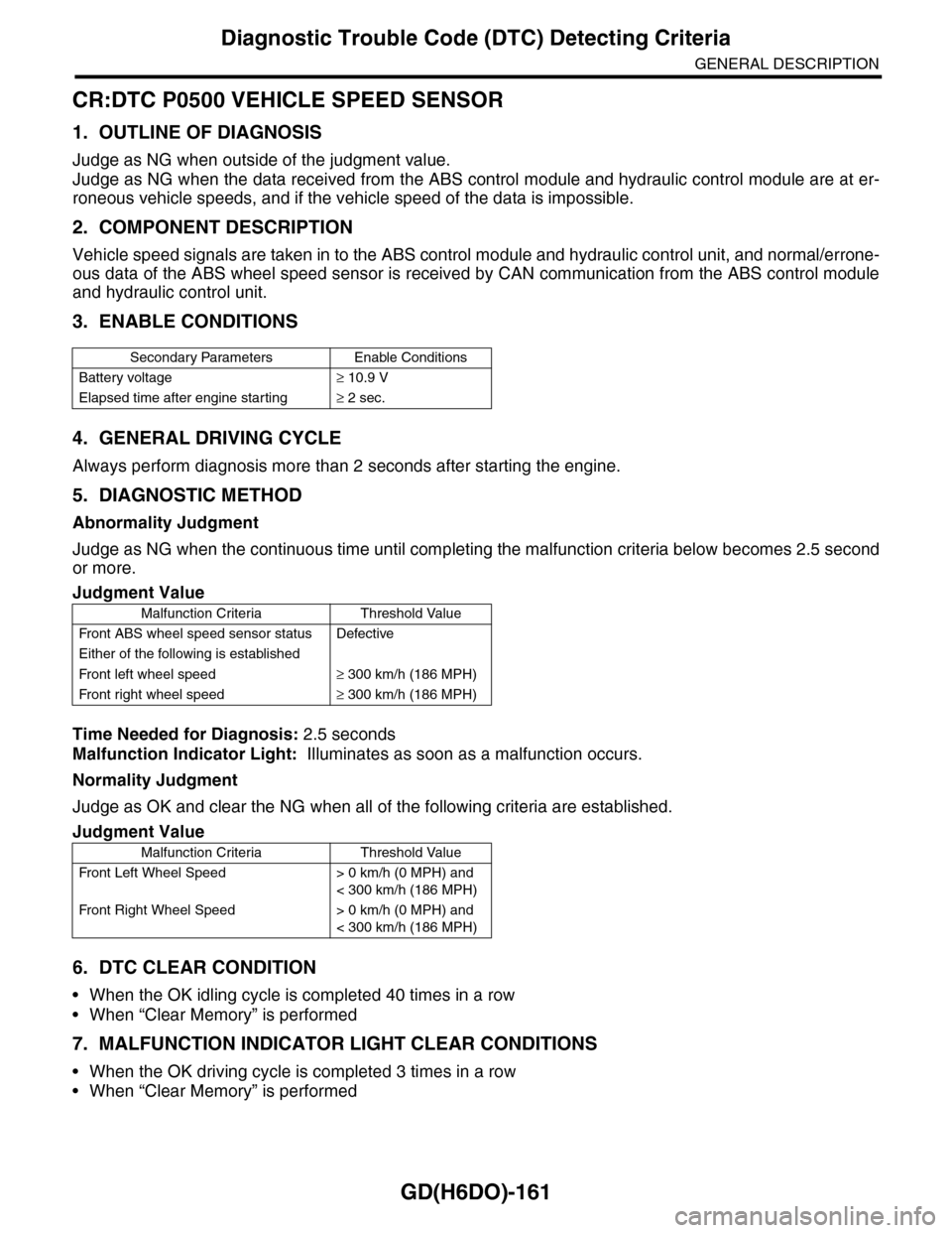
CR:DTC P0500 VEHICLE SPEED SENSOR
1. OUTLINE OF DIAGNOSIS
Judge as NG when outside of the judgment value.
Judge as NG when the data received from the ABS control module and hydraulic control module are at er-
roneous vehicle speeds, and if the vehicle speed of the data is impossible.
2. COMPONENT DESCRIPTION
Vehicle speed signals are taken in to the ABS control module and hydraulic control unit, and normal/errone-
ous data of the ABS wheel speed sensor is received by CAN communication from the ABS control module
and hydraulic control unit.
3. ENABLE CONDITIONS
4. GENERAL DRIVING CYCLE
Always perform diagnosis more than 2 seconds after starting the engine.
5. DIAGNOSTIC METHOD
Abnormality Judgment
Judge as NG when the continuous time until completing the malfunction criteria below becomes 2.5 second
or more.
Time Needed for Diagnosis: 2.5 seconds
Malfunction Indicator Light: Illuminates as soon as a malfunction occurs.
Normality Judgment
Judge as OK and clear the NG when all of the following criteria are established.
6. DTC CLEAR CONDITION
•When the OK idling cycle is completed 40 times in a row
•When “Clear Memory” is performed
7. MALFUNCTION INDICATOR LIGHT CLEAR CONDITIONS
•When the OK driving cycle is completed 3 times in a row
•When “Clear Memory” is performed
Secondary Parameters Enable Conditions
Battery voltage≥ 10.9 V
Elapsed time after engine starting≥ 2 sec.
Judgment Value
Malfunction Criteria Threshold Value
Fr o nt A B S w he e l s pe ed se n so r st at u s D efe ct i ve
Either of the following is established
Fr o nt l ef t whe e l s pe e d≥ 300 km/h (186 MPH)
Fr o nt r i gh t whe e l sp e ed≥ 300 km/h (186 MPH)
Judgment Value
Malfunction Criteria Threshold Value
Fr o nt L ef t Wh e el S pe e d > 0 km /h ( 0 M P H) a n d
< 300 km/h (186 MPH)
Fr o nt Ri gh t Wh e el S pe e d > 0 km /h ( 0 M P H) a n d
< 300 km/h (186 MPH)
Page 1774 of 2453
GD(H6DO)-162
Diagnostic Trouble Code (DTC) Detecting Criteria
GENERAL DESCRIPTION
8. FAIL SAFE
•ABS wheel speed sensor signal process: Vehicle speed = 10 km/h (6 MPH)
•ISC control: ISC feedback amount calculation prohibited
•Radiator fan control: Send the duty signal 50% to the controller.
9. ECM OPERATION AT DTC SETTING
Memorize the freeze frame data. (For test mode $02)
Page 1785 of 2453
GD(H6DO)-173
Diagnostic Trouble Code (DTC) Detecting Criteria
GENERAL DESCRIPTION
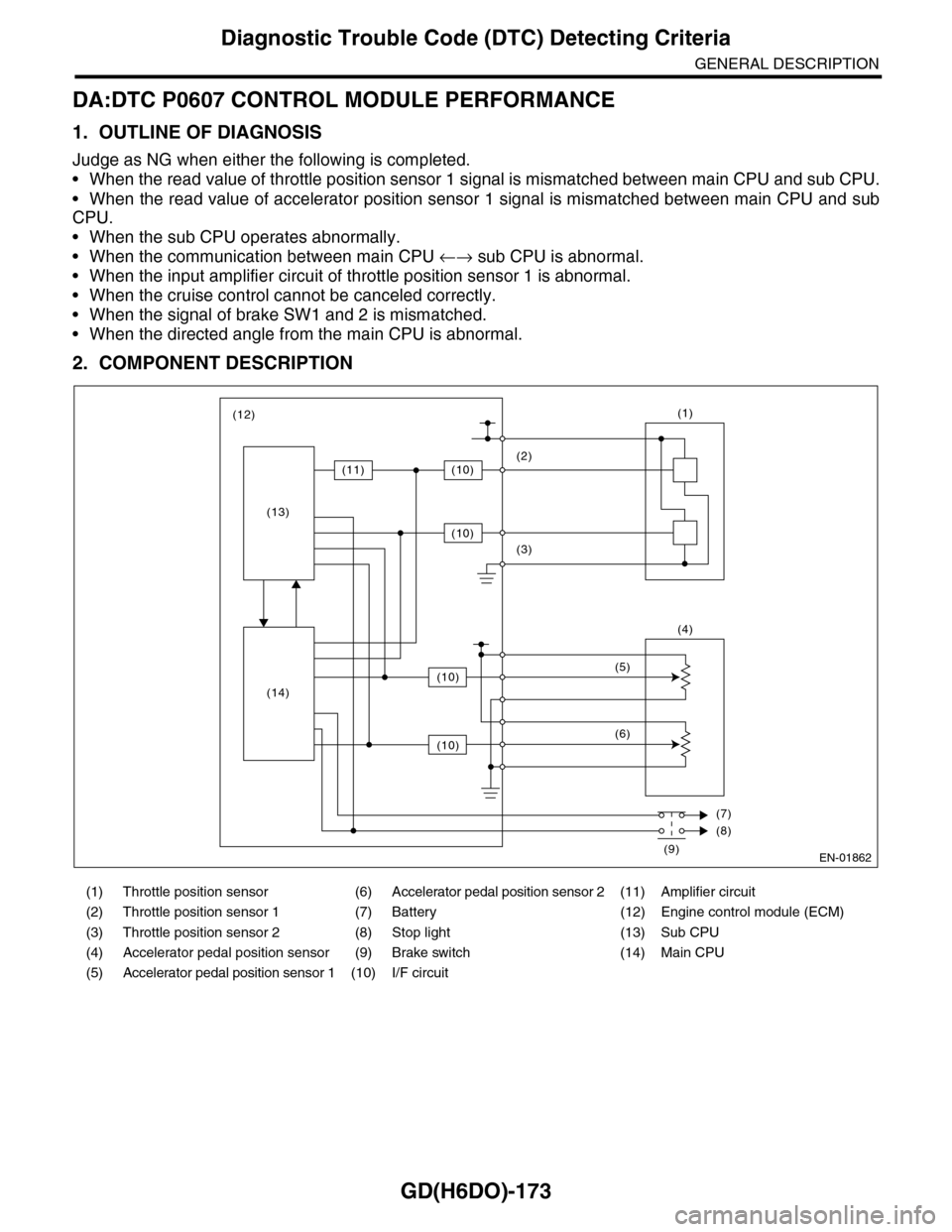
DA:DTC P0607 CONTROL MODULE PERFORMANCE
1. OUTLINE OF DIAGNOSIS
Judge as NG when either the following is completed.
•When the read value of throttle position sensor 1 signal is mismatched between main CPU and sub CPU.
•When the read value of accelerator position sensor 1 signal is mismatched between main CPU and sub
CPU.
•When the sub CPU operates abnormally.
•When the communication between main CPU ←→ sub CPU is abnormal.
•When the input amplifier circuit of throttle position sensor 1 is abnormal.
•When the cruise control cannot be canceled correctly.
•When the signal of brake SW1 and 2 is mismatched.
•When the directed angle from the main CPU is abnormal.
2. COMPONENT DESCRIPTION
(1) Throttle position sensor (6) Accelerator pedal position sensor 2 (11) Amplifier circuit
(2) Throttle position sensor 1 (7) Battery (12) Engine control module (ECM)
(3) Throttle position sensor 2 (8) Stop light (13) Sub CPU
(4) Accelerator pedal position sensor (9) Brake switch (14) Main CPU
(5) Accelerator pedal position sensor 1 (10) I/F circuit
EN-01862
(1)
(4)
(2)
(3)
(5)
(6)
(7)
(8)
(9)
(12)
(11)(10)
(10)
(10)
(10)
(13)
(14)