Page 694 of 2453
SR-10
Sunroof Switch
SUNROOF/T-TOP/CONVERTIBLE TOP (SUNROOF)
6. Sunroof Switch
A: REMOVAL
1) Disconnect the ground cable from battery.
2) Remove the spot map light lens (A) and sunroof
switch mounting screws (B).
3) Disconnect the harness connector, and then re-
move the sunroof switch.
B: INSTALLATION
Install in the reverse order of removal.
C: INSPECTION
Measure the sunroof switch resistance.
Switch position Terminal No. StandardConnector
No.
Open 1 and 3Less than
1 ΩR128
Close 3 and 4Less than
1 Ω
Tilt up 1 and 3Less than
1 ΩR187
Tilt down 3 and 4Less than
1 Ω
LI-00521
LI-00522
Page 699 of 2453
WW-4
General Description
WIPER AND WASHER SYSTEMS
3. WASHER TANK
C: CAUTION
•Connect the connectors and hoses securely during reassembly.
•After reassembly, make sure functional parts operate smoothly.
•Be careful with the airbag system wire harness which passes near electrical parts and switches.
•All airbag system wiring harness and connectors are colored yellow. Do not use a tester equipment on
these circuits.
•Care must be taken when connecting the hoses to pipes so that there are no bends or blockage.
•If even a small amount of silicon oil or grease enters tank and washer fluid passages, an oil film will be
formed on the glass and will cause the wiper to chatter and judder. Make sure that no oil comes into contact
with the system.
(1) Washer nozzle (5) Front washer motorTightening torque: N·m (kgf-m, ft-lb)
(2) Washer hose (6) Rear washer motorT: 6.0 (0.61, 4.4)
(3) Washer tank (7) Grommet
(4) Washer tank cap (8) Washer motor cover
Page 700 of 2453
WW-5
Wiper and Washer System
WIPER AND WASHER SYSTEMS
2. Wiper and Washer System
A: WIRING DIAGRAM
1. WIPER AND WASHER (FRONT)
2. WIPER AND WASHER (REAR)
B: INSPECTION
Symptom Repair order
Wiper and washers do not operate. 1. Wiper fuse (Front: F/B No. 30, Rear : F/B No. 23)
2. Combination switch
3. Wiper motor assembly
4. Wiring harness
5. Wiper relay unit
6. Body integrated unit (rear wiper only)
Wipers do not operate in LO or HI. 1. Combination switch
2. Wiper motor assembly
3. Wiring harness
4. Wiper relay unit
Wipers do not operate in INT. 1. Combination switch
2. Wiper motor assembly
3. Wiring harness
4. Body integrated unit (rear wiper only)
Wa sh e r mo to r do e s n ot o pe ra t e. 1 . Wa sh e r swit c h
2. Washer motor
3. Wiring harness
Wipers do not operate when washer switch is ON. 1. Wiper motor assembly
2. Wiring harness
Wa sh e r fl u id sp ray do e s n ot op e ra te pr o p er l y. 1 . Wa sh e r m ot o r
2. Washer hose and nozzle
Page 703 of 2453

WW-8
Combination Switch (Wiper)
WIPER AND WASHER SYSTEMS
(3) CHECK THE VEHICLE SPEED SIGNAL
HARNESS.
Measure the resistance between the wiper
switch connector and the VDC control module.
Terminals
Wiper switch connector No. 15 — VDC con-
trol module No. 33:
3. REAR WIPER
1) Check with Subaru Select Monitor
Check Yes No
Is the resistance 0 Ω?Replace the
wiper switch.
Repair the har-
ness.
Step Check Yes No
1 CHECK INPUT OF REAR WIPER SWITCH.
Check the input from body integrated unit
using the Subaru Select Monitor.
1) Connect the Subaru Select Monitor to data
link connector.
2) Turn the ignition switch to ON.
3) Select {Integ. unit} from main menu.
4) Select the {Current Data Display & Save}.
5) Check the input of the rear wiper switch.
Is the input normal? Go to step 2.Check the rear
wiper switch.
to WW-6,
INSPECTION,
Combination
Switch (Wiper).>
2CHECK OUTPUT OF BODY INTEGRATED
UNIT.
When the rear wiper switch is operated, check
the output using the Subaru Select Monitor.
1) Turn the ignition switch to ON.
2) Operate the rear wiper switch and set to
each position of ON and INT.
3) At this time, check the body integrated unit
output.
When set to ON, is ON output
continuous? When set to INT,
is ON/OFF output repeated?
(INT OFF time (when vehicle
parked): 12 seconds)
Check the rear
wiper motor.
to WW-19,
INSPECTION,
Rear Wiper
Motor.>
Replace the body
integrated unit.
Body Integrated
Unit.>
Page 704 of 2453

WW-9
Combination Switch (Wiper)
WIPER AND WASHER SYSTEMS
2) Check rear wiper motor circuit
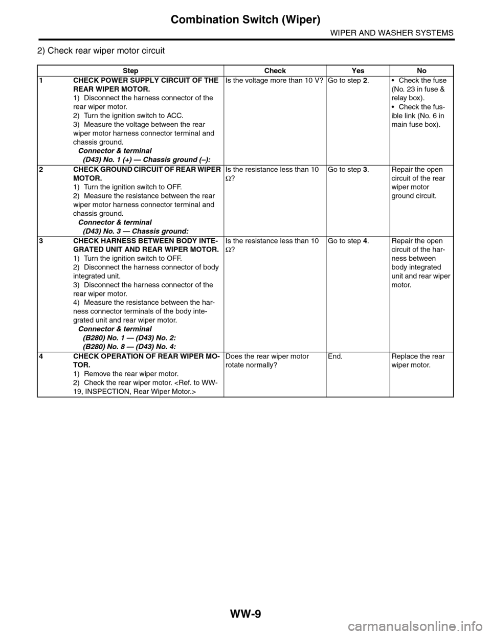
Step Check Yes No
1CHECK POWER SUPPLY CIRCUIT OF THE
REAR WIPER MOTOR.
1) Disconnect the harness connector of the
rear wiper motor.
2) Turn the ignition switch to ACC.
3) Measure the voltage between the rear
wiper motor harness connector terminal and
chassis ground.
Connector & terminal
(D43) No. 1 (+) — Chassis ground (–):
Is the voltage more than 10 V? Go to step 2.•Check the fuse
(No. 23 in fuse &
relay box).
•Check the fus-
ible link (No. 6 in
main fuse box).
2CHECK GROUND CIRCUIT OF REAR WIPER
MOTOR.
1) Turn the ignition switch to OFF.
2) Measure the resistance between the rear
wiper motor harness connector terminal and
chassis ground.
Connector & terminal
(D43) No. 3 — Chassis ground:
Is the resistance less than 10
Ω?
Go to step 3.Repair the open
circuit of the rear
wiper motor
ground circuit.
3CHECK HARNESS BETWEEN BODY INTE-
GRATED UNIT AND REAR WIPER MOTOR.
1) Turn the ignition switch to OFF.
2) Disconnect the harness connector of body
integrated unit.
3) Disconnect the harness connector of the
rear wiper motor.
4) Measure the resistance between the har-
ness connector terminals of the body inte-
grated unit and rear wiper motor.
Connector & terminal
(B280) No. 1 — (D43) No. 2:
(B280) No. 8 — (D43) No. 4:
Is the resistance less than 10
Ω?
Go to step 4.Repair the open
circuit of the har-
ness between
body integrated
unit and rear wiper
motor.
4CHECK OPERATION OF REAR WIPER MO-
TOR.
1) Remove the rear wiper motor.
2) Check the rear wiper motor.
19, INSPECTION, Rear Wiper Motor.>
Does the rear wiper motor
rotate normally?
End. Replace the rear
wiper motor.
Page 714 of 2453

WW-19
Rear Wiper Motor
WIPER AND WASHER SYSTEMS
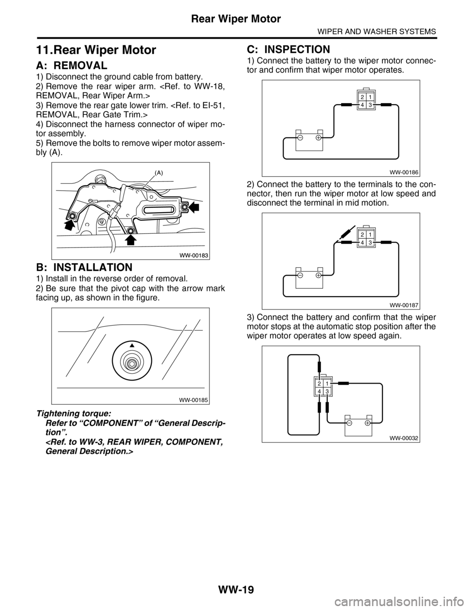
11.Rear Wiper Motor
A: REMOVAL
1) Disconnect the ground cable from battery.
2) Remove the rear wiper arm.
REMOVAL, Rear Wiper Arm.>
3) Remove the rear gate lower trim.
REMOVAL, Rear Gate Trim.>
4) Disconnect the harness connector of wiper mo-
tor assembly.
5) Remove the bolts to remove wiper motor assem-
bly (A).
B: INSTALLATION
1) Install in the reverse order of removal.
2) Be sure that the pivot cap with the arrow mark
facing up, as shown in the figure.
Tightening torque:
Refer to “COMPONENT” of “General Descrip-
tion”.
General Description.>
C: INSPECTION
1) Connect the battery to the wiper motor connec-
tor and confirm that wiper motor operates.
2) Connect the battery to the terminals to the con-
nector, then run the wiper motor at low speed and
disconnect the terminal in mid motion.
3) Connect the battery and confirm that the wiper
motor stops at the automatic stop position after the
wiper motor operates at low speed again.
WW-00185
WW-00186
21
43
WW-00187
21
43
WW-00032
21
43
Page 738 of 2453

BR-24
Master Cylinder
BRAKE
8. Master Cylinder
A: REMOVAL
CAUTION:
Do not allow brake fluid to come in contact with
vehicle body. If it does, wash off with water and
wipe away completely.
1) Drain brake fluid from the reservoir tank com-
pletely.
2) Disconnect the harness connector of the fluid
level gauge.
3) Remove the brake pipe from the master cylinder.
4) Remove the master cylinder mounting nuts, and
remove the master cylinder from the brake booster.
B: INSTALLATION
1) Install in the reverse order of removal.
Tightening torque:
Master cylinder mounting nut
25 N·m (2.5 kgf-m, 18.4 ft-lb)
Brake pipe
19 N·m (1.9 kgf-m, 14.0 ft-lb)
CAUTION:
Be sure to use recommended brake fluid.
2) Bleed air from brake system.
PROCEDURE, Air Bleeding.>
C: REPLACEMENT
1) Remove mud and dirt from the surface of brake
master cylinder.
2) Secure the master cylinder in a vise.
NOTE:
To avoid damaging the master cylinder, place be-
tween aluminum plates or other material when
holding with a vise.
3) Remove the pin which secures the master cylin-
der and reservoir tank, then remove the reservoir
tank and seal.
4) While pushing in the primary piston, remove the
C-ring using pliers.
5) While pushing in the primary piston, remove the
straight pin from the port on the reservoir tank at-
tachment location using a magnet pick-up tool.
6) Extract the primary piston assembly and sec-
ondary piston assembly straight out while taking
care not to scratch the inner surface of the cylin-
ders.
7) Clean the inside of master cylinder with brake
fluid. Check the inside of the cylinder for damage,
deformation and wear. Replace the master cylinder
as assembly if faulty.
8) Apply brake fluid to the inner surface of master
cylinder and piston assembly.
9) Make sure that the inner surface of master cylin-
der and the piston assembly are free of foreign
matter. Install the primary piston assembly and the
secondary piston assembly to master cylinder,
while taking care not to scratch the master cylinder
inner surface.
10) While pushing-in the primary piston, install the
cylinder pin.
BR-00499
(1) Straight pin
BR-00169
(1)
BR-00069
Page 749 of 2453

BR-35
Brake Pipe
BRAKE
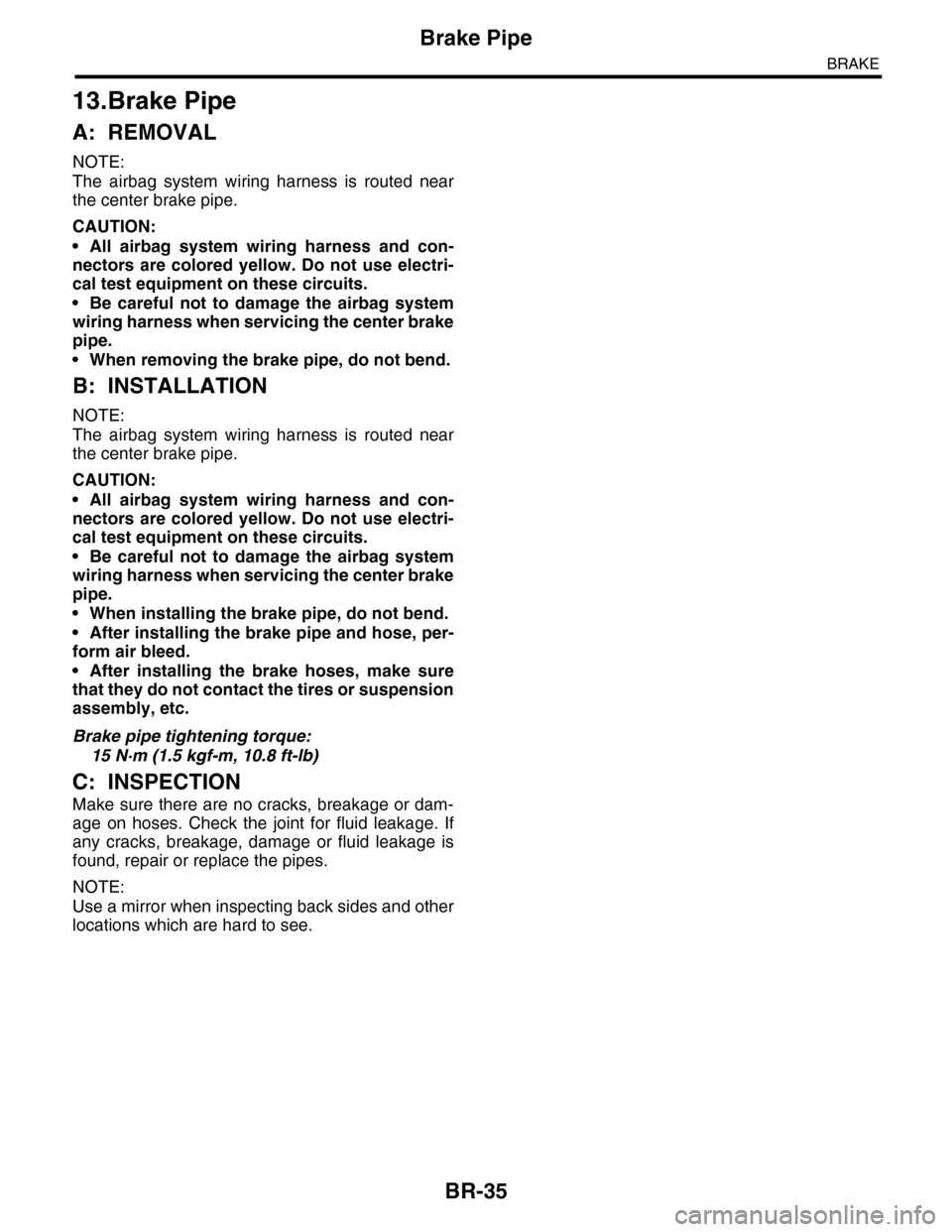
13.Brake Pipe
A: REMOVAL
NOTE:
The airbag system wiring harness is routed near
the center brake pipe.
CAUTION:
•All airbag system wiring harness and con-
nectors are colored yellow. Do not use electri-
cal test equipment on these circuits.
•Be careful not to damage the airbag system
wiring harness when servicing the center brake
pipe.
•When removing the brake pipe, do not bend.
B: INSTALLATION
NOTE:
The airbag system wiring harness is routed near
the center brake pipe.
CAUTION:
•All airbag system wiring harness and con-
nectors are colored yellow. Do not use electri-
cal test equipment on these circuits.
•Be careful not to damage the airbag system
wiring harness when servicing the center brake
pipe.
•When installing the brake pipe, do not bend.
•After installing the brake pipe and hose, per-
form air bleed.
•After installing the brake hoses, make sure
that they do not contact the tires or suspension
assembly, etc.
Brake pipe tightening torque:
15 N·m (1.5 kgf-m, 10.8 ft-lb)
C: INSPECTION
Make sure there are no cracks, breakage or dam-
age on hoses. Check the joint for fluid leakage. If
any cracks, breakage, damage or fluid leakage is
found, repair or replace the pipes.
NOTE:
Use a mirror when inspecting back sides and other
locations which are hard to see.