2009 SUBARU TRIBECA length
[x] Cancel search: lengthPage 896 of 2453

PS-16
Tilt Steering Column
POWER ASSISTED SYSTEM (POWER STEERING)
B: INSTALLATION
1) Insert the end of the steering shaft into the toe
board.
2) With the tilt lever secured, tighten the steering
shaft mounting bolts under instrument panel.
Tightening torque:
25 N·m (2.5 kgf-m, 18.1 ft-lb)
3) Connect all the connectors under the instrument
panel.
4) Connect the airbag system connector at the har-
ness spool.
NOTE:
Make sure to apply double lock.
5) Install the instrument panel lower cover with tilt
lever held in the lowered position.
6) Install the universal joint.
7) Align the center position of the roll connector.
8) Install the steering wheel.
CAUTION:
Insert the roll connector guide pin into the
guide hole on lower end of steering wheel sur-
face to prevent damage.
C: DISASSEMBLY
Remove the two screws securing the upper steer-
ing column covers, and the two screws securing
the combination switch, and then remove related
parts.
D: ASSEMBLY
Insert the combination switch to the upper column
shaft, and install the upper column cover. Then
route the ignition key harness and combination
switch harness between the column cover mount-
ing bosses.
Tightening torque:
1.2 N·m (0.12 kgf-m, 0.9 ft-lb)
CAUTION:
Do not overtorque the screw.
E: INSPECTION
1. BASIC INSPECTION
Measure the overall length of steering column. If
not within specification, replace it.
Overall length L:
Specification
917.5 +1.3 mm –0.3 mm (36.12 +0.051 in –0.020 in )
2. INSPECTION OF AIRBAG SYSTEM
WARNING:
Refer to “Airbag System” for airbag inspection
procedure.
PS-00734
L
Page 908 of 2453

PS-28
Steering Gearbox
POWER ASSISTED SYSTEM (POWER STEERING)
NOTE:
Make sure that the boot is installed without unusual
inflation or deflation.
31) Install a new boot band. Using band clamp pli-
ers, caulk it so that the clearance of caulking por-
tion becomes 2mm (0. 079 in) or less.
32) Fix the boot end with small clip.
33) After installing, check that the boot end is in-
stalled to the groove of the tie–rod.
34) If the tie-rod end has been removed, screw in
lock nut and tie-rod end to the screwed portion of
tie–rod, and tighten the lock nut temporarily in a po-
sition as shown in the figure.
Installed tie-rod length L:
31 mm (1.22 in)
35) Inspect the gearbox as follows:
Holding the “A” tie–rod end, repeat movement from
lock to lock two or three times as quickly as possi-
ble.
Holding the “B” tie–rod end, turn a few times as
slowly as possible.
Finally, make sure that the boot is installed in the
specified position without inflating.
36) Remove the gearbox from ST.
ST1 926200000 STAND
ST2 34199AG000 BOSS D
(A) Boot band
(B) Less than 2 mm (0.079 in)
PS-00194
PS-00499
(A)
(B)
(1) Clip
PS-00053
PS-00097
L
PS-00098
BA
Page 929 of 2453

PS-49
General Diagnostic Table
POWER ASSISTED SYSTEM (POWER STEERING)
10.General Diagnostic Table
A: INSPECTION
*1 If the tires or wheels are wider than standard, the load to the power steering system is increased. Accordingly, in a condition,
for example before fluid warms-up, relief valve may work before reaching maximum turning angle. In this case, steering effort
may be heavy. When the measured hydraulic pressure is normal, there is no abnormal thing. *2 In cold weather, flow resistance will increase due to the cold hydraulic fluid, and steering effort will be heavier. After warming-up en-
gine, turn the steering wheel from stop to stop several times to warm-up fluid. If steering effort reduces normally, function is normal. *3 I n c o l d w e a t h e r o r w i t h i n s u f f i c i e n t w a r m – u p o f t h e e n g i n e , s t e e r i n g e f f o r t m a y b e h e a v y d u e t o e x c e s s i v e d r o p o f i d l e r p m w h en
turning the steering wheel. In this case, start the vehicle with increasing engine speed than usual. If steering effort reduces nor-
mally, function is normal.
Tr o u b l e P o s s i b l e c a u s e C o r r e c t i v e a c t i o n
•Steering effort is heavy in all
ranges.
•Steering effort is heavy at
stand still.
•Steering wheel vibrates
when turning.
1. Pulley belt
•Unequal length of pulley belts
•Contact with oil or grease
•Looseness or damage of the pulley belt
•Poor uniformity of the pulley belt cross section
•Pulley belt touches to pulley bottom
•Poor revolution of pulleys (except oil pump pulley)
•Poor revolution of oil pump pulley
Adjust or replace.
2. Tire and wheel
•Improper tire out of specifications*1
•Improper wheel out of specifications*1
•Tires not properly inflated
Replace or reinflate.
3. Fluid
•Low fluid level
•Air entry in fluid
•Entry of dust in the fluid
•Fluid deterioration
•Inadequate warm–up of fluid *2
Refill, bleed air,
replace or instruct cus-
tomer.
4. Idle speed
•Lower idle speed
•Excessive drop of idle speed at start or when turning the steering
wheel *3
Adjust or instruct cus-
tomer.
5. Measure the hydraulic pressure.
Replace the problem
parts.
6. Measure the steering wheel effort.
•Vehicle leads to one side or
the other.
•Returning force of steering
wheel to center is poor.
•Steering wheel vibrates
when turning.
1. Fluid line
•Folded hose
•Flattened pipe
Correct or replace.
2. Tire and wheel
•Flat tire
•Mixed use of different tires
•Mixed use of different wheels
•Abnormal wear of tire
•Unequal tread remaining
•Unequal pressure of tire
Adjust, fix or replace.
3. Front alignment
•Improper or unequal caster
•Improper or unequal toe–in
•Loose suspension connections
Adjust or retighten.
4. Others
•Damaged joint assembly
•Unbalanced height
•Unbalanced weight
Replace, adjust or
instruct customer.
5. Measure the steering wheel effort.
Page 930 of 2453

PS-50
General Diagnostic Table
POWER ASSISTED SYSTEM (POWER STEERING)
1. NOISE & VIBRATION
CAUTION:
Do not keep the relief valve operated over five seconds at any time or inner parts of the oil pump may
be damaged due to rapid increase of fluid temperature.
NOTE:
•A screeching noise may be heard immediately after the engine start in extremely cold conditions. In this
case, if the noise goes off during warm-up there is no abnormal function in the system. This is due to the fluid
characteristics in extremely cold condition.
•The oil pump normally makes a small whining noise due to its mechanism. Even if a noise is heard when
steering wheel is turned at stand still, there is no abnormal function in the system provided that the noise
eliminates when the vehicle is driving.
•When turning the steering wheel with the brake applied when the vehicle is parked, a screeching noise
may be generated by the brake disc and pads. This is not a fault in the steering system.
•There may be a small vibration around the steering devices when turning the steering wheel at standstill,
even though the component parts are operating properly.
Hydraulic systems are likely to generate this kind of vibration as well as working noise and fluid noise be-
cause of combined conditions, i.e., road surface and tire surface, engine speed and turning speed of steering
wheel, fluid temperature and braking condition.
These conditions do not indicate a problem in the system.
Confirm vibration for an AT model, by applying the parking brake on a concrete surface, shifting into the “D”
range, and turning the steering wheel repeatedly from slow to rapid, step by step.
Tr o u b l e P o s s i b l e c a u s e C o r r e c t i v e a c t i o n
Hiss noise (continuous)
While engine is running.
Relief valve emits operating sound when steering wheel is
completely turned in either direction. (Do not keep this
condition over five seconds.)
Normal
Relief valve emits operating sound when steering wheel is
not turned. This means that the relief valve is defective. Replace the oil pump.
Rattling noise (intermittent)
While engine is running.
Interference with adjacent parts
Check the clearance.
Correct if necessary.
Loosened installation of oil pump, oil tank, pump bracket,
gearbox or crossmemberRetighten.
Loose oil pump pulley or other pulley(s) Retighten.
Looseness of linkage, play of steering, improper tightening
(looseness) of suspension joint or steering columnRetighten or replace.
Sound generates from the inside of gearbox or oil pump.Replace faulty parts in the gear-
box or oil pump.
Knocking
When turning steering wheel in
both directions with small angle
repeatedly at engine ON or OFF.
Excessive backlash
Loosened lock nut for adjusting backlashAdjust and retighten.
Insufficient tightening or play in the tie–rod or tie–rod end Retighten or replace.
Grinding noise (continuous)
While engine is running.
Air in vane pump
Inspect and retighten the fluid
line connection.
Refill the fluid and vent air.
Va n e p u m p s e i z i n g R e p l a c e t h e o i l p u m p.
Oil pump pulley bearing seized Replace the oil pump.
Folded hose, flattened pipe Replace.
Squeal, squeak (intermittent or
continuous)
While engine is running.
Improper adjustment of pulley belt
Damaged or over tensioned pulley belt
Unequal length of pulley belts
Adjust or replace.
(Replace two belts as a set.)
Runout or dirty V–groove surface of oil pump pulley Clean or replace.
Page 950 of 2453

RS-17
General Diagnostic Table
REAR SUSPENSION
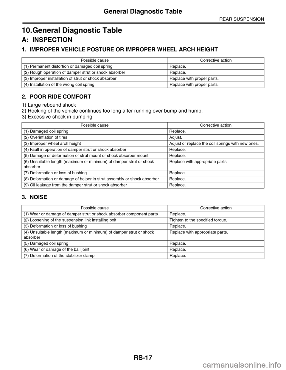
10.General Diagnostic Table
A: INSPECTION
1. IMPROPER VEHICLE POSTURE OR IMPROPER WHEEL ARCH HEIGHT
2. POOR RIDE COMFORT
1) Large rebound shock
2) Rocking of the vehicle continues too long after running over bump and hump.
3) Excessive shock in bumping
3. NOISE
Po ss ibl e c a us e C o r r e ct ive ac ti o n
(1) Permanent distortion or damaged coil spring Replace.
(2) Rough operation of damper strut or shock absorber Replace.
(3) Improper installation of strut or shock absorber Replace with proper parts.
(4) Installation of the wrong coil spring Replace with proper parts.
Po ss ibl e ca us e C or r e ct i ve a ct io n
(1) Damaged coil spring Replace.
(2) Overinflation of tires Adjust.
(3) Improper wheel arch height Adjust or replace the coil springs with new ones.
(4) Fault in operation of damper strut or shock absorber Replace.
(5) Damage or deformation of strut mount or shock absorber mount Replace.
(6) Unsuitable length (maximum or minimum) of damper strut or shock
absorber
Replace with appropriate parts.
(7) Deformation or loss of bushing Replace.
(8) Deformation or damage of helper in strut assembly or shock absorber Replace.
(9) Oil leakage from the damper strut or shock absorber Replace.
Po ss ibl e c a us e C o r r e ct ive ac ti o n
(1) Wear or damage of damper strut or shock absorber component parts Replace.
(2) Loosening of the suspension link installing bolt Tighten to the specified torque.
(3) Deformation or loss of bushing Replace.
(4) Unsuitable length (maximum or minimum) of damper strut or shock
absorber
Replace with appropriate parts.
(5) Damaged coil spring Replace.
(6) Wear or damage of the ball joint Replace.
(7) Deformation of the stabilizer clamp Replace.
Page 1837 of 2453

IG(H6DO)-2
General Description
IGNITION
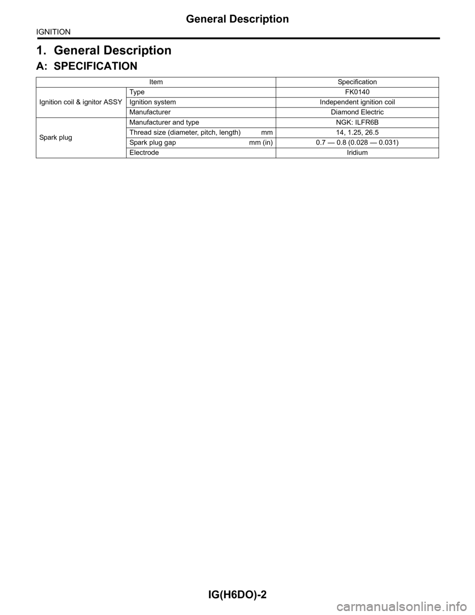
1. General Description
A: SPECIFICATION
Item Specification
Ignition coil & ignitor ASSY
Typ e F K 0 14 0
Ignition system Independent ignition coil
Manufacturer Diamond Electric
Spar k p l ug
Manufacturer and type NGK: ILFR6B
Thread size (diameter, pitch, length) mm 14, 1.25, 26.5
Spark plug gap mm (in) 0.7 — 0.8 (0.028 — 0.031)
Electrode Iridium
Page 1869 of 2453

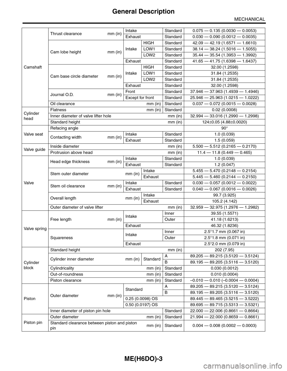
ME(H6DO)-3
General Description
MECHANICAL
Camshaft
Thrust clearance mm (in)Intake Standard 0.075 — 0.135 (0.0030 — 0.0053)
Exhaust Standard 0.030 — 0.090 (0.0012 — 0.0035)
Cam lobe height mm (in)Intake
HIGH Standard 42.09 — 42.19 (1.6571 — 1.6610)
LOW1 Standard 38.14 — 38.24 (1.5016 — 1.5055)
LOW2 Standard 35.44 — 35.54 (1.3953 — 1.3992)
Exhaust Standard 41.65 — 41.75 (1.6398 — 1.6437)
Cam base circle diameter mm (in)Intake
HIGH Standard 32.00 (1.2598)
LOW1 Standard 31.84 (1.2535)
LOW2 Standard 31.84 (1.2535)
Exhaust Standard 32.00 (1.2598)
Journal O.D. mm (in)Fr o nt S ta n da r d 3 7. 9 46 — 3 7 . 96 3 ( 1 . 49 3 9 — 1. 4 9 46 )
Except for front Standard 25.946 — 25.963 (1.0215 — 1.0222)
Oil clearance mm (in) Standard 0.037 — 0.072 (0.0015 — 0.0028)
Cylinder
head
Flatness mm (in) Standard 0.02 (0.0008)
Inner diameter of valve lifter hole mm (in) 32.994 — 33.016 (1.2990 — 1.2998)
Standard height mm (in) 124±0.05 (4.88±0.0020)
Va l ve s e a t
Refacing angle90°
Contacting width mm (in)Intake Standard 1.0 (0.039)
Exhaust Standard 1.5 (0.059)
Va l ve g u i d eInside diameter mm (in) 5.500 — 5.512 (0.2165 — 0.2170)
Protrusion above head mm (in) 11.4 — 11.8 (0.449 — 0.465)
Va l ve
Head edge thickness mm (in)Intake Standard 1.0 (0.039)
Exhaust Standard 1.2 (0.047)
Stem outer diameter mm (in)Intake 5.455 — 5.470 (0.2148 — 0.2154)
Exhaust 5.445 — 5.460 (0.2144 — 0.2150)
Stem oil clearance mm (in)Intake Standard 0.030 — 0.057 (0.0012 — 0.0022)
Exhaust Standard 0.040 — 0.067 (0.0016 — 0.0026)
Overall length mm (in)Intake 99.7 (3.925)
Exhaust 105.2 (4.142)
Outer diameter of valve lifter mm (in) 32.959 — 32.975 (1.2976 — 1.2982)
Va l ve s p r i n g
Free length mm (in)IntakeInner 39.55 (1.5571)
Outer 41.18 (1.6213)
Exhaust 46.32 (1.8236)
SquarenessIntakeInner 2.5°1.7 mm (0.067 in)
Outer 2.5°1.8 mm (0.071 in)
Exhaust 2.5°2.0 mm (0.079 in)
Cylinder
block
Standard height mm (in) 202 (7.95)
Cylinder inner diameter mm (in) StandardA89.205 — 89.215 (3.5120 — 3.5124)
B89.195 — 89.205 (3.5116 — 3.5120)
Cylindricality mm (in) Standard 0.030 (0.0012)
Out-of-roundness mm (in) Standard 0.010 (0.0004)
Piston clearance mm (in) Standard –0.010 — 0.010 (–0.0004 — 0.0004)
PistonOuter diameter mm (in)
StandardA89.205 — 89.215 (3.5120 — 3.5124)
B89.195 — 89.205 (3.5116 — 3.5120)
0.25 (0.0098) OS 89.445 — 89.465 (3.5215 — 3.5222)
0.50 (0.0197) OS 89.695 — 89.715 (3.5313 — 3.5321)
Inner diameter of piston pin hole Standard 22.000 — 22.006 (0.8661 — 0.8664)
Piston pin
Outer diameter mm (in) Standard 21.994 — 22.000 (0.8659 — 0.8661)
Standard clearance between piston and piston
pinmm (in) Standard 0.004 — 0.008 (0.0002 — 0.0003)
Page 1926 of 2453

ME(H6DO)-60
Cylinder Head
MECHANICAL
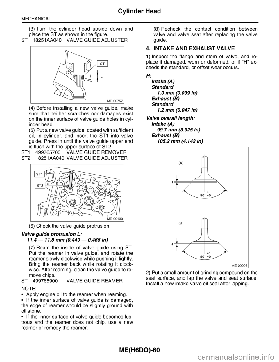
(3) Turn the cylinder head upside down and
place the ST as shown in the figure.
ST 18251AA040 VALVE GUIDE ADJUSTER
(4) Before installing a new valve guide, make
sure that neither scratches nor damages exist
on the inner surface of valve guide holes in cyl-
inder head.
(5) Put a new valve guide, coated with sufficient
oil, in cylinder, and insert the ST1 into valve
guide. Press in until the valve guide upper end
is flush with the upper surface of ST2.
ST1 499765700 VALVE GUIDE REMOVER
ST2 18251AA040 VALVE GUIDE ADJUSTER
(6) Check the valve guide protrusion.
Valve guide protrusion L:
11.4 — 11.8 mm (0.449 — 0.465 in)
(7) Ream the inside of valve guide using ST.
Put the reamer in valve guide, and rotate the
reamer slowly clockwise while pushing it lightly.
Bring the reamer back while rotating it clock-
wise. After reaming, clean the valve guide to re-
move chips.
ST 499765900 VALVE GUIDE REAMER
NOTE:
•Apply engine oil to the reamer when reaming.
•If the inner surface of valve guide is damaged,
the edge of reamer should be slightly ground with
oil stone.
•If the inner surface of valve guide becomes lus-
trous and the reamer does not chip, use a new
reamer or remedy the reamer.
(8) Recheck the contact condition between
valve and valve seat after replacing the valve
guide.
4. INTAKE AND EXHAUST VALVE
1) Inspect the flange and stem of valve, and re-
place if damaged, worn or deformed, or if “H” ex-
ceeds the standard, or offset wear occurs.
H:
Intake (A)
Standard
1.0 mm (0.039 in)
Exhaust (B)
Standard
1.2 mm (0.047 in)
Valve overall length:
Intake (A)
99.7 mm (3.925 in)
Exhaust (B)
105.2 mm (4.142 in)
2) Put a small amount of grinding compound on the
seat surface, and lap the valve and seat surface.
Install a new intake valve oil seal after lapping.
ME-00757
ST
L
ME-00130
ST1
ST2
ME-02096
H
H
(B)
(A)
90 0+1
90 0+1