2009 SUBARU TRIBECA length
[x] Cancel search: lengthPage 12 of 2453
AB-13
Inspection Locations After a Collision
AIRBAG SYSTEM
2. PASSENGER’S AIRBAG MODULE
Check for the following, and replace the damaged
parts with new parts.
•Airbag module and instrument panel are cracked
or deformed.
•Harness and/or connector is cracked, deformed
or open. Harness wire is exposed.
•Mounting bracket is cracked or deformed.
3. SIDE AIRBAG MODULE
Check for the following, and replace the damaged
parts with new parts.
•Front seat, airbag module and mounting bracket
are damaged or deformed.
•Harness and/or connector is cracked, deformed
or open. Harness wire is exposed.
4. CURTAIN AIRBAG MODULE
Check for the following, and replace the damaged
parts with new parts.
•Airbag cover is scratched or broken.
•Harness and/or connector is cracked, deformed
or open. Harness wire is exposed.
•Mounting bracket and securing clip are cracked
or deformed.
5. AIRBAG CONTROL MODULE
Check for the following, and replace the damaged
parts with new parts.
•Control module is cracked or deformed.
•Mounting bracket is cracked or deformed.
•Connector is scratched, cracked or deformed.
•Airbag is deployed.
•Side airbag is deployed.
•Curtain airbag is deployed.
6. FRONT SUB SENSOR
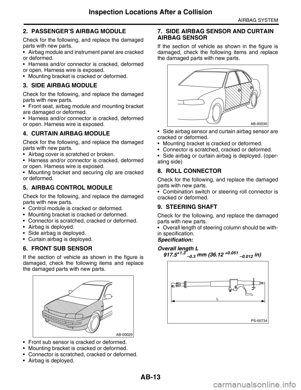
If the section of vehicle as shown in the figure is
damaged, check the following items and replace
the damaged parts with new parts.
•Front sub sensor is cracked or deformed.
•Mounting bracket is cracked or deformed.
•Connector is scratched, cracked or deformed.
•Airbag is deployed.
7. SIDE AIRBAG SENSOR AND CURTAIN
AIRBAG SENSOR
If the section of vehicle as shown in the figure is
damaged, check the following items and replace
the damaged parts with new parts.
•Side airbag sensor and curtain airbag sensor are
cracked or deformed.
•Mounting bracket is cracked or deformed.
•Connector is scratched, cracked or deformed.
•Side airbag or curtain airbag is deployed. (oper-
ating side)
8. ROLL CONNECTOR
Check for the following, and replace the damaged
parts with new parts.
•Combination switch or steering roll connector is
cracked or deformed.
9. STEERING SHAFT
Check for the following, and replace the damaged
parts with new parts.
•Overall length of steering column should be with-
in specification.
Specification:
Overall length L
917.5+1.3 –0.3 mm (36.12 +0.051 –0.012 in)
AB-00029
AB-00030
PS-00734
L
Page 267 of 2453

EI-25
Front Bumper
EXTERIOR/INTERIOR TRIM
3) Deep damage such as a break or hole that requires filling
Much of the peripheral grained surface must be sacrificed for repair. The degree of restoration is not really
worth the expense. (The surface, however, will become almost flush with adjacent areas. )
Recommended repair kit: PP Part Repair Kit (NRM)
Process
No.Process name Job contents
1Bumper removalRemove the bumper as required.
2Removal of partsRemove the parts built into bumper as required.
3Bumper placement
Place the bumper on a paint worktable as
required.
It is recommended to use the paint worktable
conforming to internal shape of bumper.
(1) Bumper
(2) Set bumper section
4Surface prepara-
tion
Remove dust, oil, etc. from areas to be repaired and surrounding areas, using a suitable solvent
(NRM No. 900 Precleno, white gasoline, or alcohol, etc.).
5Cutting
If the damage is a crack or a hole, cut a guide
slit of 20 to 30 mm (0.79 to 1.18 in) in length
along the crack or hole up to the bumper base
surface. Next, use a knife or grinder to carve a
V- s h a p e d g r o o ve i n t h e a r e a f o r r e p a i r.
(1) Paint surface
(2) PP base surface
(3) 20 — 30 mm (0.79 — 1.18 in)
(4) 3 mm (0.12 in)
6Sanding (I) Grind beveled surface with sand paper (#40 — #60) to smooth finish.
7Cleaning Clean the sanded surface with the same solvent as used in Procedure 4.
8Temporary welding
Grind the side just opposite the beveled area with sand paper (#40 — #60) and clean using a
solvent.
Te m p o r a r i l y s p o t - w e l d t h e s i d e , u s i n g P P w e l d i n g r o d a n d h e a t e r g u n .
(1) Welded point (Use heater gun and PP welding rod)
(2) PP base surface
(3) Beveled section
NOTE:•Do not melt welding rod until it flows out. This results in reduced strength.
•Leave the welded spot unattended until it cools completely.
EI-00234(2)
(1)
EI-00235
(4)(2)
(1)(3)
EI-00236
(1)
(2)
(3)
Page 328 of 2453

AC-2
General Description
HVAC SYSTEM (HEATER, VENTILATOR AND A/C)
1. General Description
A: SPECIFICATION
1. HEATER SYSTEM
2. A/C SYSTEM
•Single A/C model (front only)
Item Specification Condition
Heating capacity5.2 kW (4,471 kcal/h, 17,743
BTU/h) or more
•Mode selector switch: HEAT
•Temperature control switch: FULL HOT
•Temperature difference between hot water and inlet
air: 65°C (149°F)
•Hot water flow rate: 360 2 (95.1 US gal, 79.2 Imp
gal)/h
Air flow rate340 m3 (11,301 cu ft)/hHeat mode (FRESH), FULL HOT at 12.5 V
Max air flow rate550 m3 (16,245 cu ft)/h
•Temperature control switch: FULL COLD
•Blower fan speed:
6th position
•Mode selector lever: RECIRC
Heater core size
(height × length × width)
264 × 110 × 27 mm
(10.4 × 4.33 × 1.06 in)—
Blower Motor
Ty p e B r u s h m o t o r 2 2 0 W o r l e s s 1 2 V
Fa n t y pe an d si ze
(diameter × width)
Sirocco fan type
165 ×75 mm (6.51 × 2.95 in)—
Item Specification
Ty p e o f a i r c o n d i t i o n e r R e h e a t a i r - m i x t y p e
Cooling capacity6.2 kW
(5,331 kcal/h, 21,154 BTU/h)
RefrigerantHFC-134a (CH2FCF3)
[0.87±0.03 kg (1.92±0.07 lb)]
Compressor
Ty p eInclined plate (SWASH PLATE), fixed capacity
(10SR17), Temperature fuse
Exhaust 177 cc (10.80 cu in)/rev
Max. permissible speed 6,000 rpm
Magnet clutch
Ty p e D r y, s i n g l e - d i s c t y p e
Powe r c on su mp t i on 35 W
Ty p e o f b e l t V- b e l t 6 P K
Pulley dia. (effective dia.) 115 mm (4.53 in)
Pulley ratio 1.16
Condenser
Ty p e C o r r u g a t e d f i n ( S u b c o o l t y p e )
Core face area0.29 m2 (3.122 sq ft)
Core thickness 16 mm (0.63 in)
Radiation area7.65 m2 (82.35 sq ft)
Receiver drier Effective inner capacity190 cm3 (11.6 cu in)
Expansion valve Type Box time (external pressure equalizing type)
Evaporator
Ty p e S i n g l e t a n k
Dimensions (W × H × T)293.1 × 211 × 38 mm
(11.54 × 8.31 × 1.50 in)
Blower fan
Fan t yp e S i r oc co fa n
Outer diameter× width 165 ×75 mm (6.50 × 2.95 in)
Powe r c on su mp t i on 2 60 W
Page 350 of 2453
AC-24
Refrigerant Leak Check
HVAC SYSTEM (HEATER, VENTILATOR AND A/C)
5. Refrigerant Leak Check
A: INSPECTION
1) At engine speed below 1500rpm, operate the A/
C system for approx. 10 minutes, and confirm that
the high-side pressure shows at least 690 kPa
(7.03 kg/cm2, 100 psi). Then stop the engine to
start the leak test.
2) Starting from the connection between high-pres-
sure pipe and evaporator, check the system for
leaks along the high-pressure side through the
compressor. The following items must be checked
thoroughly.
3) Check the joint and seam between pressure
switch (dual switch) and high-pressure pipe.
4) Check the connections between condenser and
pipes, and welded joints on the condenser.
The leak tester may detect the oil on the condenser
fins as a leak.
5) Check the joint between compressor and hoses.
6) Check the machined area of the compressor and
other joints on the compressor.
7) Check the compressor shaft seal at the area
near the center of compressor clutch pulley.
Some shaft seals show a slight amount of leakage,
about 3 g (0.1 oz) per year. This is not a problem.
8) Starting from the connection between low-pres-
sure pipe and evaporator, check the system for
leakage along the low-pressure side through the
compressor. The following items must be checked
thoroughly.
•Connection between 2 parts
•Connection between pipe and plate
•Connection between pipes
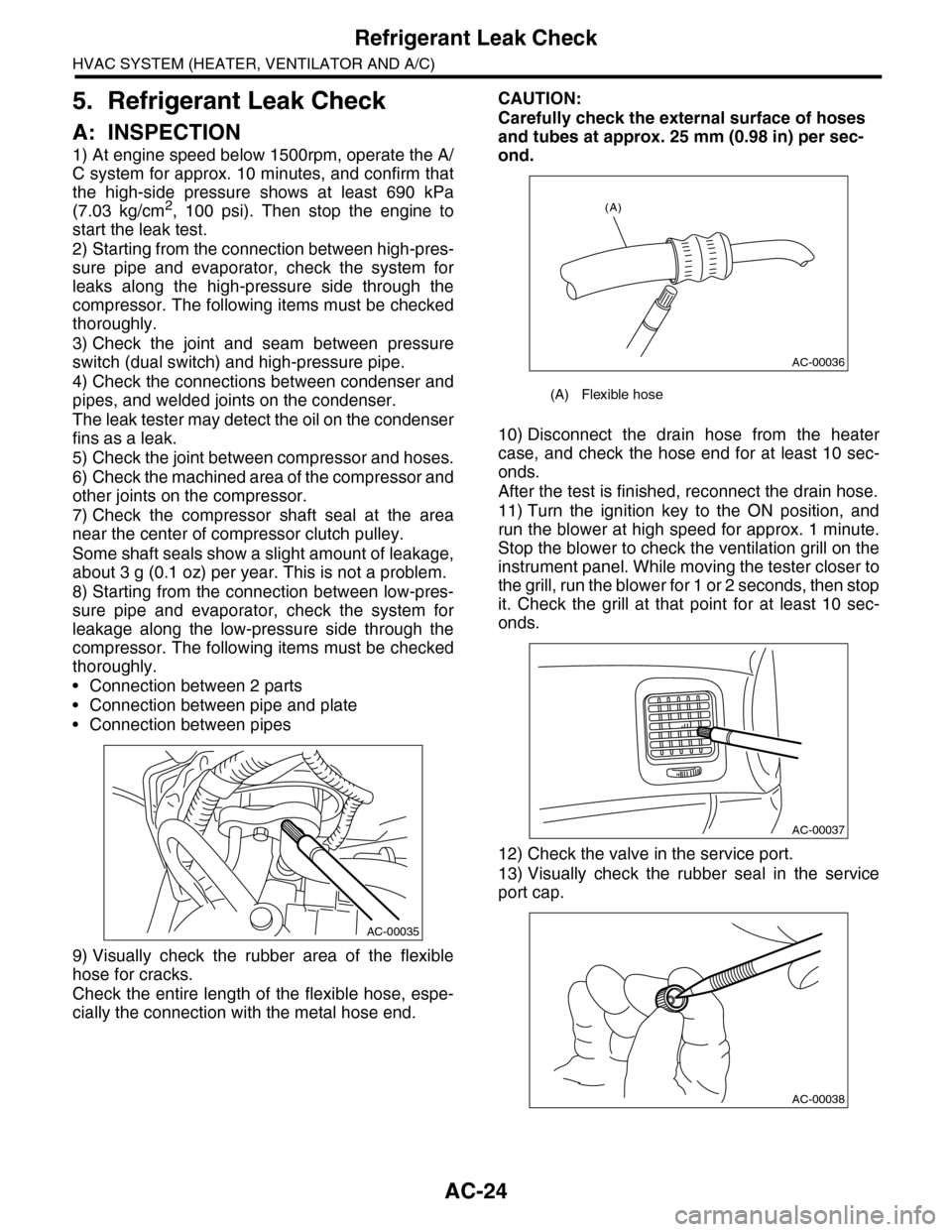
9) Visually check the rubber area of the flexible
hose for cracks.
Check the entire length of the flexible hose, espe-
cially the connection with the metal hose end.
CAUTION:
Carefully check the external surface of hoses
and tubes at approx. 25 mm (0.98 in) per sec-
ond.
10) Disconnect the drain hose from the heater
case, and check the hose end for at least 10 sec-
onds.
After the test is finished, reconnect the drain hose.
11) Turn the ignition key to the ON position, and
run the blower at high speed for approx. 1 minute.
Stop the blower to check the ventilation grill on the
instrument panel. While moving the tester closer to
the grill, run the blower for 1 or 2 seconds, then stop
it. Check the grill at that point for at least 10 sec-
onds.
12) Check the valve in the service port.
13) Visually check the rubber seal in the service
port cap.
AC-00035
(A) Flexible hose
AC-00036
(A)
AC-00037
AC-00038
Page 461 of 2453
LAN(diag)-5
General Description
LAN SYSTEM (DIAGNOSTICS)
3. General Description
A: CAUTION
1. SRS AIRBAG SYSTEM
Airbag system wiring harness is routed near the
body integrated unit and twisted pair line.
CAUTION:
•All airbag system wiring harness and con-
nectors are colored yellow. Do not use the elec-
trical test equipment on these circuits.
•Be careful not to damage the airbag system
wiring harness when servicing the body inte-
grated unit and LAN system.
•Refer to “Airbag System” when disconnect-
ing the air bag system connector.
2. LAN SYSTEM
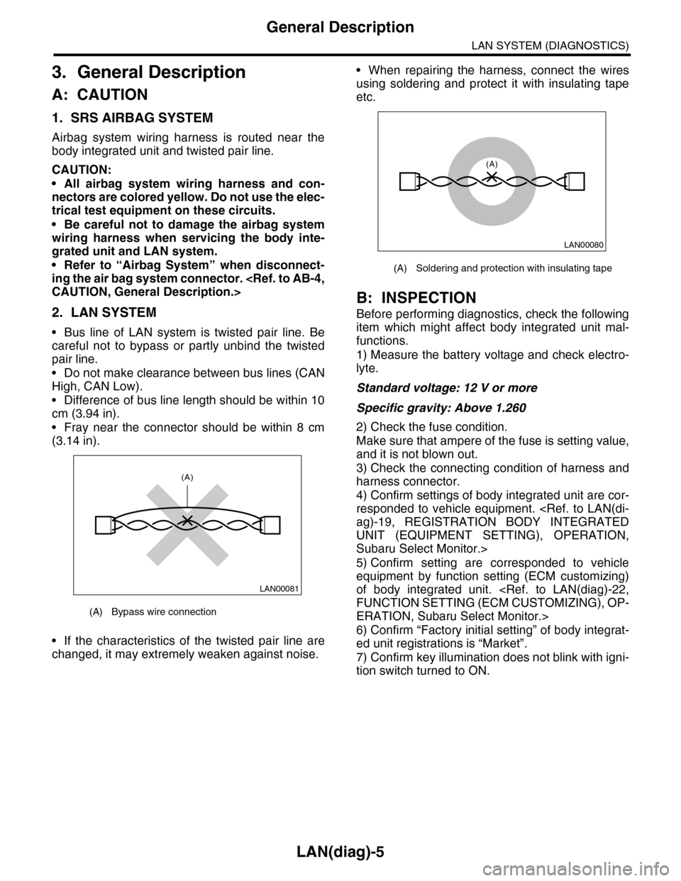
•Bus line of LAN system is twisted pair line. Be
careful not to bypass or partly unbind the twisted
pair line.
•Do not make clearance between bus lines (CAN
High, CAN Low).
•Difference of bus line length should be within 10
cm (3.94 in).
•Fray near the connector should be within 8 cm
(3.14 in).
•If the characteristics of the twisted pair line are
changed, it may extremely weaken against noise.
•When repairing the harness, connect the wires
using soldering and protect it with insulating tape
etc.
B: INSPECTION
Before performing diagnostics, check the following
item which might affect body integrated unit mal-
functions.
1) Measure the battery voltage and check electro-
lyte.
Standard voltage: 12 V or more
Specific gravity: Above 1.260
2) Check the fuse condition.
Make sure that ampere of the fuse is setting value,
and it is not blown out.
3) Check the connecting condition of harness and
harness connector.
4) Confirm settings of body integrated unit are cor-
responded to vehicle equipment.
UNIT (EQUIPMENT SETTING), OPERATION,
Subaru Select Monitor.>
5) Confirm setting are corresponded to vehicle
equipment by function setting (ECM customizing)
of body integrated unit.
ERATION, Subaru Select Monitor.>
6) Confirm “Factory initial setting” of body integrat-
ed unit registrations is “Market”.
7) Confirm key illumination does not blink with igni-
tion switch turned to ON.
(A) Bypass wire connection
LAN00081
(A)
(A) Soldering and protection with insulating tape
LAN00080
(A)
Page 691 of 2453
SR-7
Sunroof Assembly
SUNROOF/T-TOP/CONVERTIBLE TOP (SUNROOF)
4. Sunroof Assembly
A: REMOVAL
1) Disconnect the ground cable from battery.
2) Remove the roof trim.
3) Disconnect the harness connector of sunroof
motor.
4) Remove the glass lid.
5) Remove the drain tube from frame assembly.
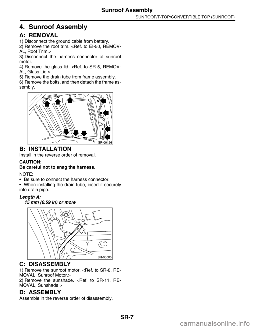
6) Remove the bolts, and then detach the frame as-
sembly.
B: INSTALLATION
Install in the reverse order of removal.
CAUTION:
Be careful not to snag the harness.
NOTE:
•Be sure to connect the harness connector.
•When installing the drain tube, insert it securely
into drain pipe.
Length A:
15 mm (0.59 in) or more
C: DISASSEMBLY
1) Remove the sunroof motor.
2) Remove the sunshade.
D: ASSEMBLY
Assemble in the reverse order of disassembly.
SR-00005
A
Page 716 of 2453
BR-2
General Description
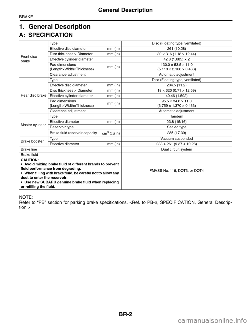
BRAKE
1. General Description
A: SPECIFICATION
NOTE:
Refer to “PB” section for parking brake specifications.
Fr o nt d is c
brake
Ty p e D i s c ( F l o a t i n g t y p e , v e n t i l a t e d )
Effective disc diameter mm (in) 261 (10.28)
Disc thickness × Diameter mm (in) 30 × 316 (1.18 × 12.44)
Effective cylinder diameter 42.8 (1.685) × 2
Pad dimensions
(Length×Width×Thickness)mm (in)130.0 × 53.5 × 11.0
(5.118 × 2.106 × 0.433)
Clearance adjustment Automatic adjustment
Rear disc brake
Ty p e D i s c ( F l o a t i n g t y p e , v e n t i l a t e d )
Effective disc diameter mm (in) 284.5 (11.2)
Disc thickness × Diameter mm (in) 18 × 320 (0.71 × 12.59)
Effective cylinder diameter mm (in) 40.46 (1.592)
Pad dimensions
(Length×Width×Thickness)mm (in)95.5 × 34.8 × 11.0
(3.759 × 1.370 × 0.433)
Clearance adjustment Automatic adjustment
Master cylinder
Ty p e Ta n d e m
Effective diameter mm (in) 23.8 (15/16)
Reservoir type Sealed type
Brake fluid reservoir capacitycm3 (cu in)285 (17.39)
Brake boosterTy p e V a c u u m s u s p e n d e d
Effective diameter mm (in) 238 + 261 (9.37 + 10.28)
Brake lineDual circuit system
Brake fluid
CAUTION:
•Avoid mixing brake fluid of different brands to prevent
fluid performance from degrading.
•When filling with brake fluid, be careful not to allow any
dust to enter the reservoir.
•Use new SUBARU genuine brake fluid when replacing
or refilling the fluid.
FMVSS No. 116, DOT3, or DOT4
Page 740 of 2453
BR-26
Brake Booster
BRAKE
9. Brake Booster
A: REMOVAL
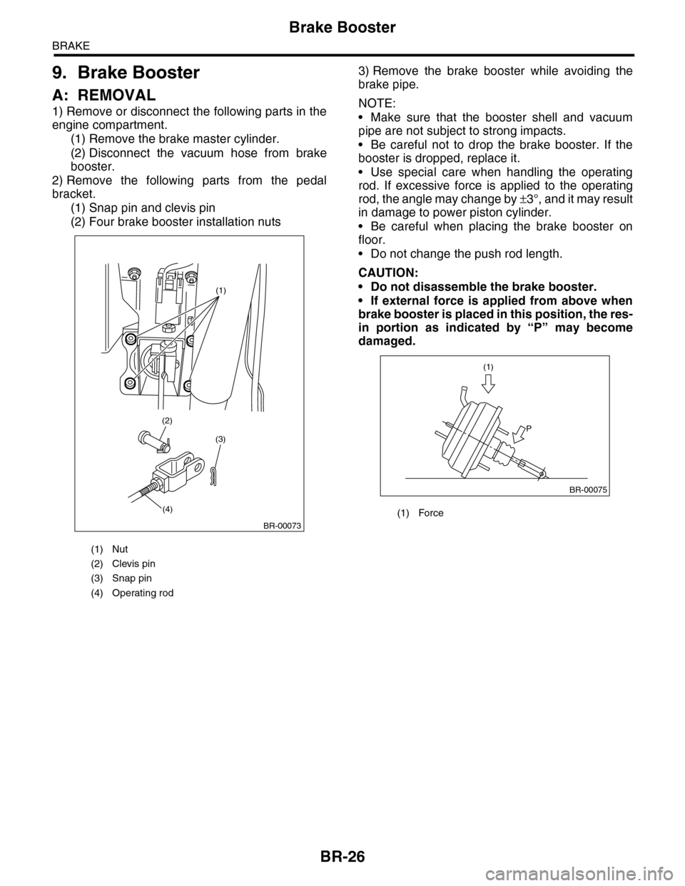
1) Remove or disconnect the following parts in the
engine compartment.
(1) Remove the brake master cylinder.
(2) Disconnect the vacuum hose from brake
booster.
2) Remove the following parts from the pedal
bracket.
(1) Snap pin and clevis pin
(2) Four brake booster installation nuts
3) Remove the brake booster while avoiding the
brake pipe.
NOTE:
•Make sure that the booster shell and vacuum
pipe are not subject to strong impacts.
•Be careful not to drop the brake booster. If the
booster is dropped, replace it.
•Use special care when handling the operating
rod. If excessive force is applied to the operating
rod, the angle may change by ±3°, and it may result
in damage to power piston cylinder.
•Be careful when placing the brake booster on
floor.
•Do not change the push rod length.
CAUTION:
•Do not disassemble the brake booster.
•If external force is applied from above when
brake booster is placed in this position, the res-
in portion as indicated by “P” may become
damaged.
(1) Nut
(2) Clevis pin
(3) Snap pin
(4) Operating rod
(1)
(3)
(4)
(2)
BR-00073
(1) Force
(1)
P
BR-00075