Page 750 of 2453

BR-36
Brake Pedal
BRAKE
14.Brake Pedal
A: REMOVAL
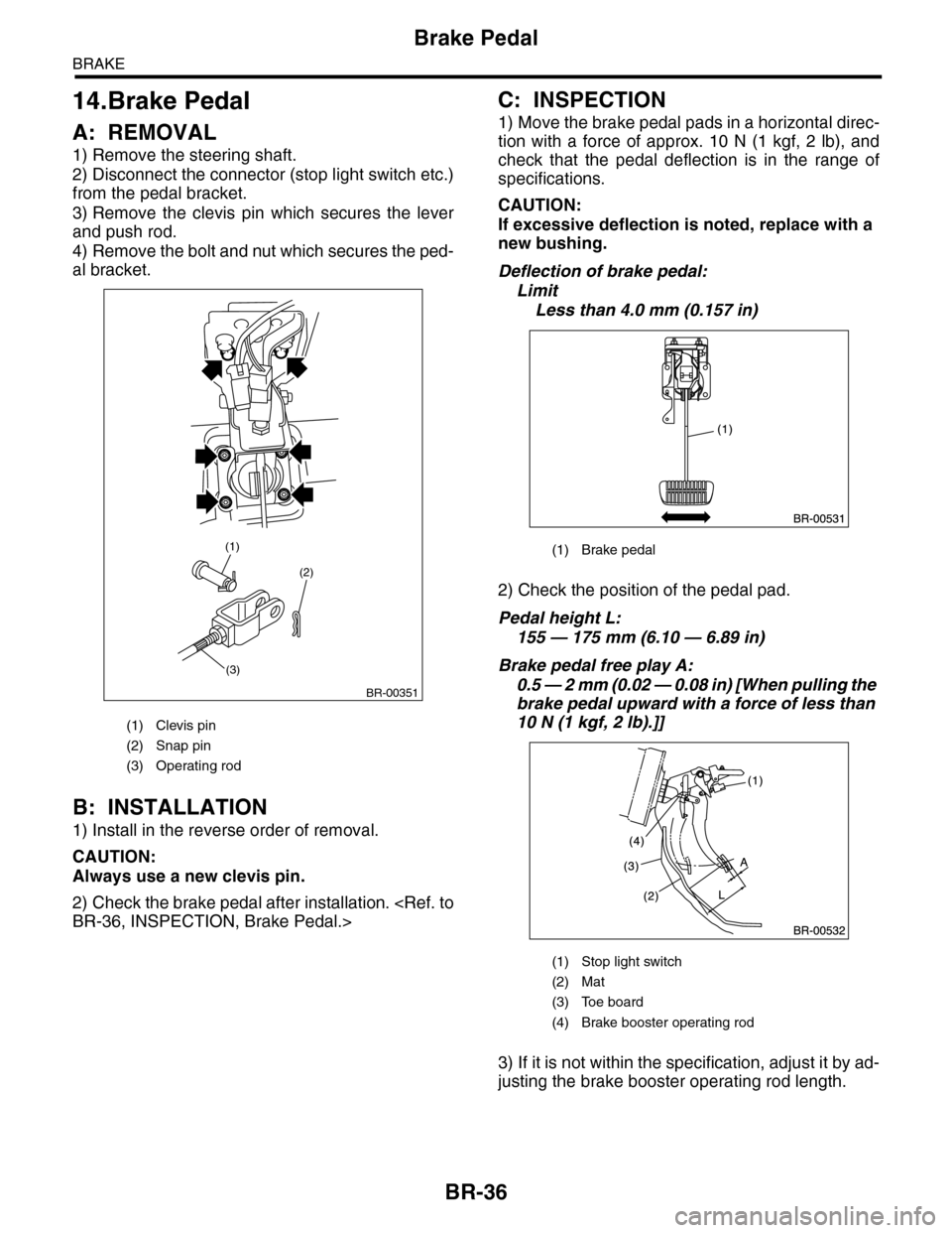
1) Remove the steering shaft.
2) Disconnect the connector (stop light switch etc.)
from the pedal bracket.
3) Remove the clevis pin which secures the lever
and push rod.
4) Remove the bolt and nut which secures the ped-
al bracket.
B: INSTALLATION
1) Install in the reverse order of removal.
CAUTION:
Always use a new clevis pin.
2) Check the brake pedal after installation.
BR-36, INSPECTION, Brake Pedal.>
C: INSPECTION
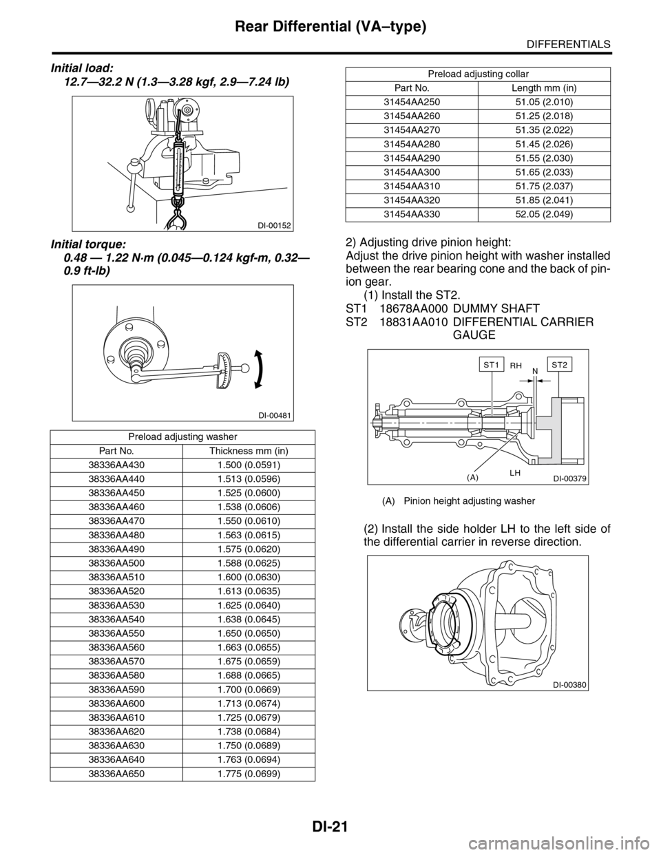
1) Move the brake pedal pads in a horizontal direc-
tion with a force of approx. 10 N (1 kgf, 2 lb), and
check that the pedal deflection is in the range of
specifications.
CAUTION:
If excessive deflection is noted, replace with a
new bushing.
Deflection of brake pedal:
Limit
Less than 4.0 mm (0.157 in)
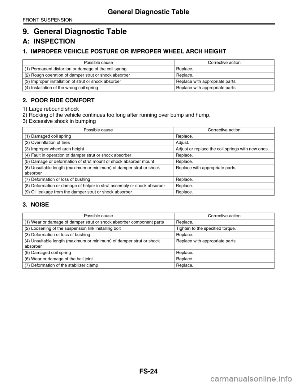
2) Check the position of the pedal pad.
Pedal height L:
155 — 175 mm (6.10 — 6.89 in)
Brake pedal free play A:
0.5 — 2 mm (0.02 — 0.08 in) [When pulling the
brake pedal upward with a force of less than
10 N (1 kgf, 2 lb).]]
3) If it is not within the specification, adjust it by ad-
justing the brake booster operating rod length.
(1) Clevis pin
(2) Snap pin
(3) Operating rod
(2)
(3)
(1)
BR-00351
(1) Brake pedal
(1) Stop light switch
(2) Mat
(3) Toe board
(4) Brake booster operating rod
Page 787 of 2453

DI-3
General Description
DIFFERENTIALS
5. ADJUSTING PARTS
Drive pinion bearing preload
Measure with spring measurement. (Mea-
sured from the companion flange bolt)
N (kgf, lb)
12.7 — 32.2 (1.3 — 3.28, 2.9 — 7.24)
Measure with torque wrench
N·m (kgf–m, ft–lb)0.48 — 1.22 (0.045 — 0.124, 0.32 — 0.9)
Preload adjusting collar
Par t No. Length mm (in)
31454AA250 51.05 (2.010)
31454AA260 51.25 (2.018)
31454AA270 51.35 (2.022)
31454AA280 51.45 (2.026)
31454AA290 51.55 (2.030)
31454AA300 51.65 (2.033)
31454AA310 51.75 (2.037)
31454AA320 51.85 (2.041)
31454AA330 52.05 (2.049)
Preload adjusting washer
Par t No. Thickness mm (in)
38336AA430 1.500 (0.0591)
38336AA440 1.513 (0.0596)
38336AA450 1.525 (0.0600)
38336AA460 1.538 (0.0606)
38336AA470 1.550 (0.0610)
38336AA480 1.563 (0.0615)
38336AA490 1.575 (0.0620)
38336AA500 1.588 (0.0625)
38336AA510 1.600 (0.0630)
38336AA520 1.613 (0.0635)
38336AA530 1.625 (0.0640)
38336AA540 1.638 (0.0645)
38336AA550 1.650 (0.0650)
38336AA560 1.663 (0.0655)
38336AA570 1.675 (0.0659)
38336AA580 1.688 (0.0665)
38336AA590 1.700 (0.0669)
38336AA600 1.713 (0.0674)
38336AA610 1.725 (0.0679)
38336AA620 1.738 (0.0684)
38336AA630 1.750 (0.0689)
38336AA640 1.763 (0.0694)
38336AA650 1.775 (0.0699)
Pinion height adjusting washer
Par t No. Thickness mm (in)
32295AA350 0.150 (0.0059)
32295AA360 0.175 (0.0069)
32295AA370 0.200 (0.0079)
32295AA380 0.225 (0.0089)
32295AA390 0.250 (0.0098)
32295AA400 0.275 (0.0108)
Hypoid driven gear to drive pinion
backlashLimit mm (in) 0.10 — 0.15 (0.0039 — 0.0059)
Page 805 of 2453

DI-21
Rear Differential (VA–type)
DIFFERENTIALS
Initial load:
12.7—32.2 N (1.3—3.28 kgf, 2.9—7.24 lb)
Initial torque:
0.48 — 1.22 N·m (0.045—0.124 kgf-m, 0.32—
0.9 ft-lb)
2) Adjusting drive pinion height:
Adjust the drive pinion height with washer installed
between the rear bearing cone and the back of pin-
ion gear.
(1) Install the ST2.
ST1 18678AA000 DUMMY SHAFT
ST2 18831AA010 DIFFERENTIAL CARRIER
GAUGE
(2) Install the side holder LH to the left side of
the differential carrier in reverse direction.
Preload adjusting washer
Par t No. Thickness mm (in)
38336AA430 1.500 (0.0591)
38336AA440 1.513 (0.0596)
38336AA450 1.525 (0.0600)
38336AA460 1.538 (0.0606)
38336AA470 1.550 (0.0610)
38336AA480 1.563 (0.0615)
38336AA490 1.575 (0.0620)
38336AA500 1.588 (0.0625)
38336AA510 1.600 (0.0630)
38336AA520 1.613 (0.0635)
38336AA530 1.625 (0.0640)
38336AA540 1.638 (0.0645)
38336AA550 1.650 (0.0650)
38336AA560 1.663 (0.0655)
38336AA570 1.675 (0.0659)
38336AA580 1.688 (0.0665)
38336AA590 1.700 (0.0669)
38336AA600 1.713 (0.0674)
38336AA610 1.725 (0.0679)
38336AA620 1.738 (0.0684)
38336AA630 1.750 (0.0689)
38336AA640 1.763 (0.0694)
38336AA650 1.775 (0.0699)
DI-00152
DI-00481
Preload adjusting collar
Par t No. Length mm (in)
31454AA250 51.05 (2.010)
31454AA260 51.25 (2.018)
31454AA270 51.35 (2.022)
31454AA280 51.45 (2.026)
31454AA290 51.55 (2.030)
31454AA300 51.65 (2.033)
31454AA310 51.75 (2.037)
31454AA320 51.85 (2.041)
31454AA330 52.05 (2.049)
(A) Pinion height adjusting washer
RH
LH
N
(A)
ST2ST1
DI-00379
DI-00380
Page 819 of 2453
DS-2
General Description
DRIVE SHAFT SYSTEM
1. General Description
A: SPECIFICATION
1. PROPELLER SHAFT
Propeller shaft typeEDJ
Propeller shaft length: L mm (in) 1,399 (55.08)
Fr o nt p r op el l er s ha f t J oi n t -t o - jo i nt l en g th : L1mm (in) 645 (25.39)
Rear propeller shaft Joint-to-Joint length: L2mm (in) 754 (29.69)
Outer diameter of tube: mm (in)D163.5 (2.50)
D257.5 (2.26)
D1 D2
L
L1 L2
DS-00350
Page 820 of 2453
DS-3
General Description
DRIVE SHAFT SYSTEM
2. FRONT DRIVE SHAFT ASSEMBLY
3. REAR DRIVE SHAFT ASSEMBLY
Ty p e o f d r i v e s h a f t A x l e d i a m e t e rφ D mm (in) Axle length L mm (in)
EBJ+PTJ 26 (1.0) 388.5 (15.30)
(A) Axle diameter (B) Axle length
Ty p e o f d r i v e s h a f t A x l e d i a m e t e rφ D mm (in) Axle length L mm (in)
EBJ+DOJ 24 (0.94) 386.8 (15.23)
(A) Axle diameter (B) Axle length
Page 863 of 2453

FS-15
Front Ball Joint
FRONT SUSPENSION
5. Front Ball Joint
A: REMOVAL
1) Lift-up the vehicle, and remove the front wheels.
2) Remove the both sides of stabilizer bracket.
3) Pull out the pin from ball stud, remove the castle
nut, and extract the ball stud from front arm.
4) Remove the bolt installing ball joint to housing.
5) Extract the ball joint from housing.
B: INSTALLATION
1) Insert the ball joint into housing.
Tightening torque (Bolt):
50 N·m (5.1 kgf-m, 36.9 ft-lb)
CAUTION:
Do not apply grease to the tapered portion of
ball stud.
2) Install the ball joint into front arm.
Tightening torque (castle nut):
Front arm
45 N·m (4.6 kgf-m, 33.2 ft-lb)
3) Retighten the castle nut further up to 60° until the
hole in the ball stud is aligned with a slot in castle
nut. Then, insert a new cotter pin and bend it
around the castle nut.
4) Install the stabilizer bracket.
Tightening torque:
25 N·m (2.5 kgf-m, 18.1 ft-lb)
5) Install the front wheels.
C: INSPECTION
1) Measure the play of the ball joint using the fol-
lowing procedures. Replace with a new part if the
play exceeds specification.
(1) With 980 N (100 kgf, 220 lb) loaded in direc-
tion shown in the figure, measure the length
21.
(2) With 980 N (100 kgf, 220lb) loaded in direc-
tion shown in the figure, measure the length
22.
(3) Determine free play using the following for-
mula.
S = 22 – 21(4) Replace with a new part if the play exceeds
specification.
FRONT BALL JOINT
Specification for replacement S:
Less than 0.3 mm (0.012 in)
2) If the play is within specification, visually check
the dust cover.
3) Remove the ball joint and cover, and check for
wear, damage or cracks. If any damage is found,
replace the corresponding part.
4) If the dust cover is damaged, replace with a new
ball joint.
FS-00202
FS-00115
FS-00035
FS-00036
Page 872 of 2453

FS-24
General Diagnostic Table
FRONT SUSPENSION
9. General Diagnostic Table
A: INSPECTION
1. IMPROPER VEHICLE POSTURE OR IMPROPER WHEEL ARCH HEIGHT
2. POOR RIDE COMFORT
1) Large rebound shock
2) Rocking of the vehicle continues too long after running over bump and hump.
3) Excessive shock in bumping
3. NOISE
Po ss ibl e c a us e C o r r e ct ive ac ti o n
(1) Permanent distortion or damage of the coil spring Replace.
(2) Rough operation of damper strut or shock absorber Replace.
(3) Improper installation of strut or shock absorber Replace with appropriate parts.
(4) Installation of the wrong coil spring Replace with appropriate parts.
Po ss ibl e ca us e C or r e ct i ve a ct io n
(1) Damaged coil spring Replace.
(2) Overinflation of tires Adjust.
(3) Improper wheel arch height Adjust or replace the coil springs with new ones.
(4) Fault in operation of damper strut or shock absorber Replace.
(5) Damage or deformation of strut mount or shock absorber mount Replace.
(6) Unsuitable length (maximum or minimum) of damper strut or shock
absorber
Replace with appropriate parts.
(7) Deformation or loss of bushing Replace.
(8) Deformation or damage of helper in strut assembly or shock absorber Replace.
(9) Oil leakage from the damper strut or shock absorber Replace.
Po ss ibl e c a us e C o r r e ct ive ac ti o n
(1) Wear or damage of damper strut or shock absorber component parts Replace.
(2) Loosening of the suspension link installing bolt Tighten to the specified torque.
(3) Deformation or loss of bushing Replace.
(4) Unsuitable length (maximum or minimum) of damper strut or shock
absorber
Replace with appropriate parts.
(5) Damaged coil spring Replace.
(6) Wear or damage of the ball joint Replace.
(7) Deformation of the stabilizer clamp Replace.
Page 873 of 2453
PB-2
General Description
PARKING BRAKE
1. General Description
A: SPECIFICATION
B: COMPONENT
1. PARKING BRAKE (REAR DISC BRAKE)
Ty p e M e c h a n i c a l , d r u m i n d i s c r e a r b r a k e s
Effective drum diameter mm (in) 210 (8.27)
Lining dimensions
(Length×Width×Thickness)mm (in)238.2 × 30.0 × 4.0
(9.378 × 1.181 × 0.157)
Clearance adjustment Manual adjustment
Pe da l s t ro ke n o tc he s /N ( k gf, lb ) 5 — 6 / 3 00 ( 30 . 6, 6 7)
(1) Back plate (8) Strut (15) Shoe hold pin
(2) Retainer (9) Primary return spring (16) Self locking nut (with WAX)
(3) Spring washer (10) Secondary return spring
(4) Lever (11) Adjusting springTightening torque: N·m (kgf-m, ft-lb)
(5) Parking brake shoe (Primary) (12) AdjusterT1: 8 (0.8, 5.9)
(6) Parking brake shoe (Secondary) (13) Brake shoe cupT2: 75 (7.6, 55.33)
(7) Strut spring (14) Brake shoe spring
PB-00083
(5)
(14)
(13)
(12)(9)
(11)
(10)
(8)
(7)
(6)
(4)(3)(2)
(1)
(15)
(16)
T1
T2