Page 1927 of 2453
ME(H6DO)-61
Cylinder Head
MECHANICAL
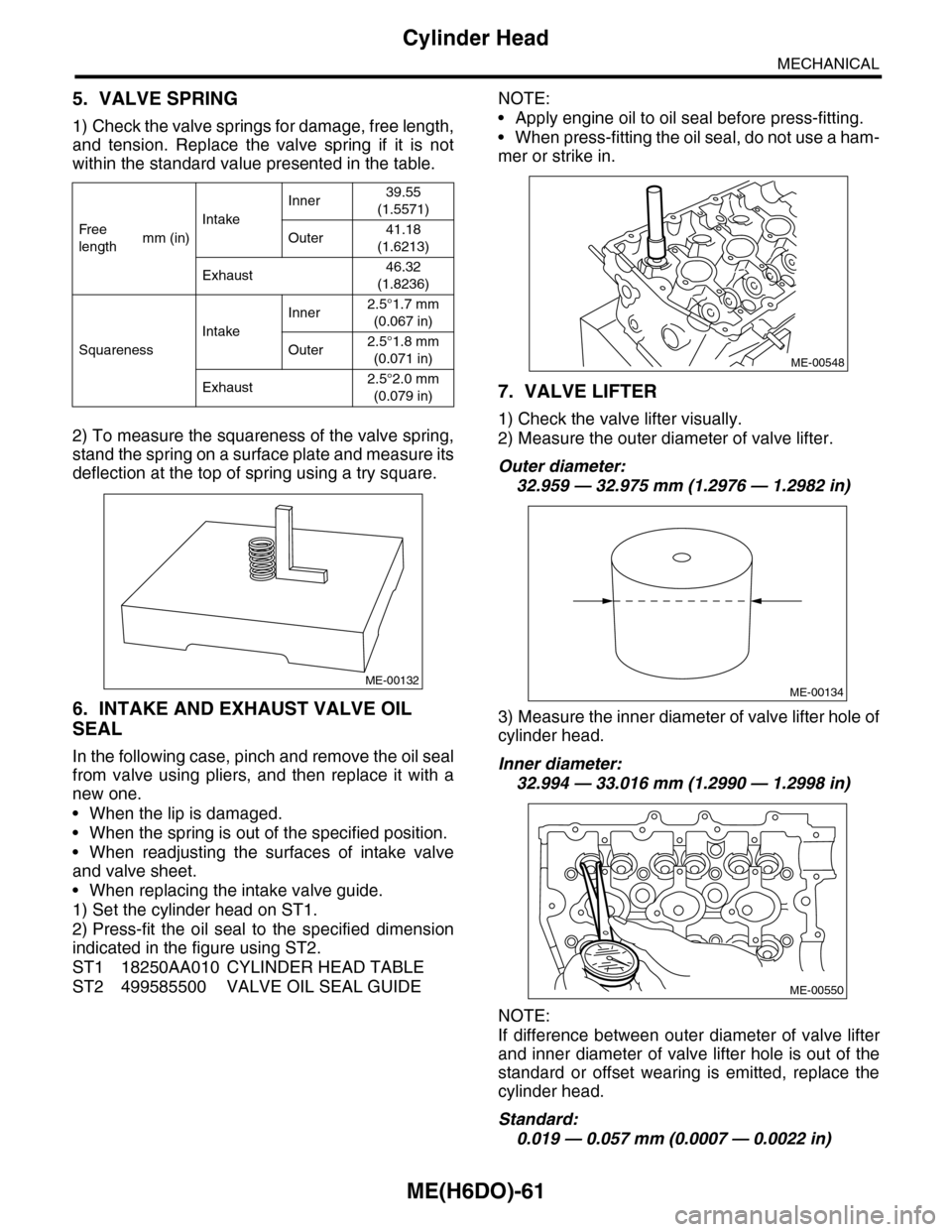
5. VALVE SPRING
1) Check the valve springs for damage, free length,
and tension. Replace the valve spring if it is not
within the standard value presented in the table.
2) To measure the squareness of the valve spring,
stand the spring on a surface plate and measure its
deflection at the top of spring using a try square.
6. INTAKE AND EXHAUST VALVE OIL
SEAL
In the following case, pinch and remove the oil seal
from valve using pliers, and then replace it with a
new one.
•When the lip is damaged.
•When the spring is out of the specified position.
•When readjusting the surfaces of intake valve
and valve sheet.
•When replacing the intake valve guide.
1) Set the cylinder head on ST1.
2) Press-fit the oil seal to the specified dimension
indicated in the figure using ST2.
ST1 18250AA010 CYLINDER HEAD TABLE
ST2 499585500 VALVE OIL SEAL GUIDE
NOTE:
•Apply engine oil to oil seal before press-fitting.
•When press-fitting the oil seal, do not use a ham-
mer or strike in.
7. VALVE LIFTER
1) Check the valve lifter visually.
2) Measure the outer diameter of valve lifter.
Outer diameter:
32.959 — 32.975 mm (1.2976 — 1.2982 in)
3) Measure the inner diameter of valve lifter hole of
cylinder head.
Inner diameter:
32.994 — 33.016 mm (1.2990 — 1.2998 in)
NOTE:
If difference between outer diameter of valve lifter
and inner diameter of valve lifter hole is out of the
standard or offset wearing is emitted, replace the
cylinder head.
Standard:
0.019 — 0.057 mm (0.0007 — 0.0022 in)
Fr e e
lengthmm (in)
Intake
Inner39.55
(1.5571)
Outer41.18
(1.6213)
Exhaust46.32
(1.8236)
Squareness
Intake
Inner2.5°1.7 mm
(0.067 in)
Outer2.5°1.8 mm
(0.071 in)
Exhaust2.5°2.0 mm
(0.079 in)
ME-00132
ME-00548
ME-00134
ME-00550
Page 1973 of 2453
SC(H6DO)-15
Starter
STARTING/CHARGING SYSTEMS
E: INSPECTION
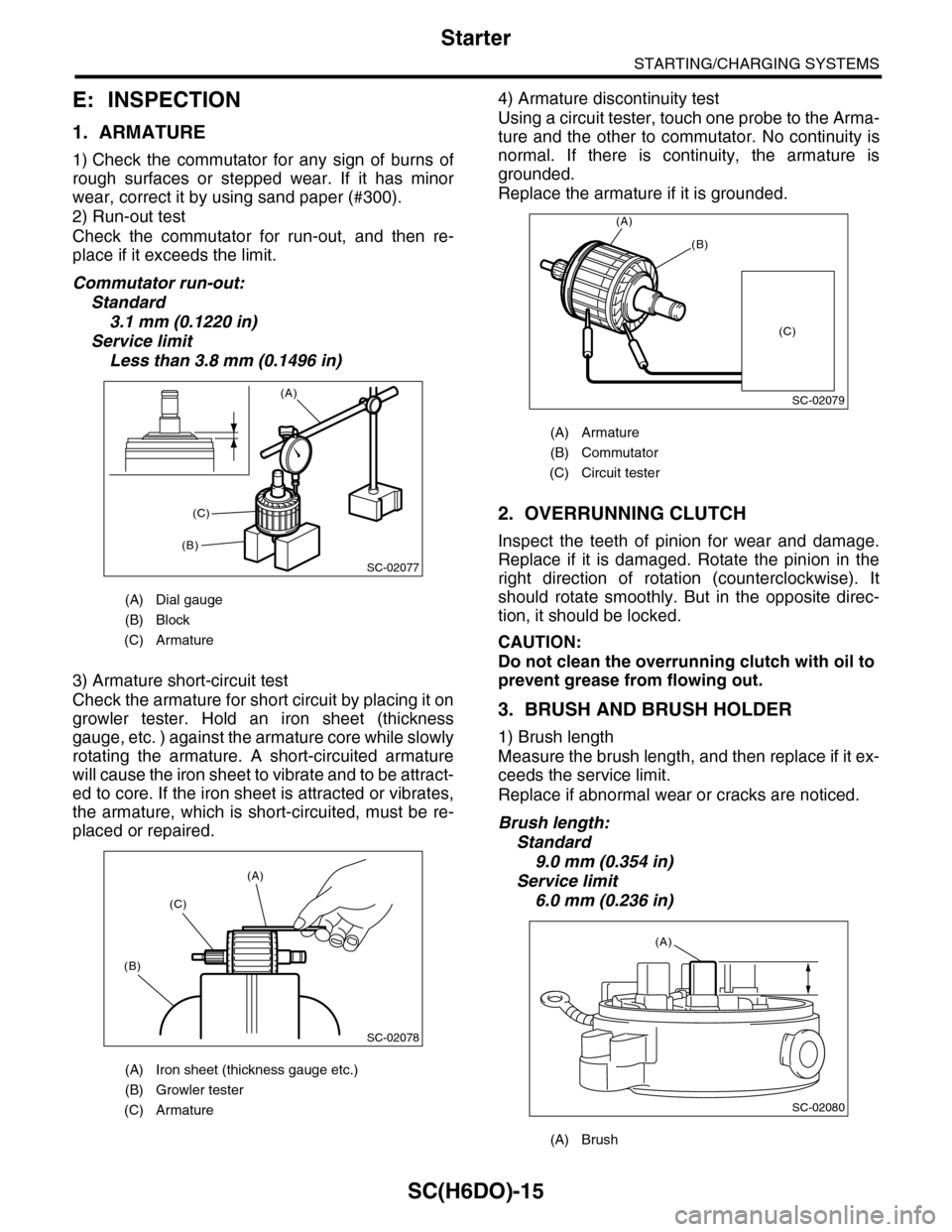
1. ARMATURE
1) Check the commutator for any sign of burns of
rough surfaces or stepped wear. If it has minor
wear, correct it by using sand paper (#300).
2) Run-out test
Check the commutator for run-out, and then re-
place if it exceeds the limit.
Commutator run-out:
Standard
3.1 mm (0.1220 in)
Service limit
Less than 3.8 mm (0.1496 in)
3) Armature short-circuit test
Check the armature for short circuit by placing it on
growler tester. Hold an iron sheet (thickness
gauge, etc. ) against the armature core while slowly
rotating the armature. A short-circuited armature
will cause the iron sheet to vibrate and to be attract-
ed to core. If the iron sheet is attracted or vibrates,
the armature, which is short-circuited, must be re-
placed or repaired.
4) Armature discontinuity test
Using a circuit tester, touch one probe to the Arma-
ture and the other to commutator. No continuity is
normal. If there is continuity, the armature is
grounded.
Replace the armature if it is grounded.
2. OVERRUNNING CLUTCH
Inspect the teeth of pinion for wear and damage.
Replace if it is damaged. Rotate the pinion in the
right direction of rotation (counterclockwise). It
should rotate smoothly. But in the opposite direc-
tion, it should be locked.
CAUTION:
Do not clean the overrunning clutch with oil to
prevent grease from flowing out.
3. BRUSH AND BRUSH HOLDER
1) Brush length
Measure the brush length, and then replace if it ex-
ceeds the service limit.
Replace if abnormal wear or cracks are noticed.
Brush length:
Standard
9.0 mm (0.354 in)
Service limit
6.0 mm (0.236 in)
(A) Dial gauge
(B) Block
(C) Armature
(A) Iron sheet (thickness gauge etc.)
(B) Growler tester
(C) Armature
SC-02077
(A)
(B)
(C)
SC-02078
(A)
(C)
(B)
(A) Armature
(B) Commutator
(C) Circuit tester
(A) Brush
SC-02079
(A)
(B)
(C)
SC-02080
(A)
Page 1982 of 2453
SC(H6DO)-24
Generator
STARTING/CHARGING SYSTEMS
4. BRUSH
1) Measure the length of each brush. If wear ex-
ceeds the service limit, replace the brush. Each
brush has the service limit mark (A) on it.
Brush length:
Service limit (1)
5.0 mm (0.197 in)
Standard (2)
18.5 mm (0.728 in)
2) Checking brush spring for proper pressure
Using a spring pressure indicator, push the brush
into the brush holder until its tip protrudes 2 mm
(0.08 in). Then measure the pressure of brush
spring. If the pressure is less than 2.2 N (224 g, 7
91 oz), replace the brush spring with a new one.
The new spring must have a pressure of 4.8 to 6.0
N (489 to 612 g, 17.26 to 21.58 oz).
5. BEARING (FRONT SIDE)
Check the front ball bearing. If the resistance is felt
while rotating, or abnormal noise is heard, replace
the ball bearing
SC-00162
(A)
(1)
(2)
SC-00093
Page 2053 of 2453
5AT-37
Automatic Transmission Assembly
AUTOMATIC TRANSMISSION
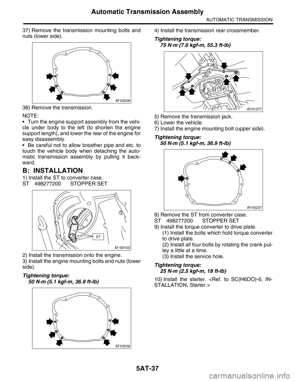
37) Remove the transmission mounting bolts and
nuts (lower side).
38) Remove the transmission.
NOTE:
•Turn the engine support assembly from the vehi-
cle under body to the left (to shorten the engine
support length), and lower the rear of the engine for
easy disassembly.
•Be careful not to allow breather pipe and etc. to
touch the vehicle body when detaching the auto-
matic transmission assembly by pulling it back-
ward.
B: INSTALLATION
1) Install the ST to converter case.
ST 498277200 STOPPER SET
2) Install the transmission onto the engine.
3) Install the engine mounting bolts and nuts (lower
side).
Tightening torque:
50 N·m (5.1 kgf-m, 36.9 ft-lb)
4) Install the transmission rear crossmember.
Tightening torque:
75 N·m (7.6 kgf-m, 55.3 ft-lb)
5) Remove the transmission jack.
6) Lower the vehicle.
7) Install the engine mounting bolt (upper side).
Tightening torque:
50 N·m (5.1 kgf-m, 36.9 ft-lb)
8) Remove the ST from converter case.
ST 498277200 STOPPER SET
9) Install the torque converter to drive plate.
(1) Install the bolts which hold torque converter
to drive plate.
(2) Install all four bolts by rotating the crank pul-
ley a little at a time.
(3) Install the service hole.
Tightening torque:
25 N·m (2.5 kgf-m, 18 ft-lb)
10) Install the starter.
STALLATION, Starter.>
AT-03238
AT-00103
ST
AT-03238
AT-01377
AT-03237
Page 2071 of 2453
5AT-55
ATF Filter
AUTOMATIC TRANSMISSION
18.ATF Filter
A: REMOVAL
1) Remove the front bumper.
MOVAL, Front Bumper.>
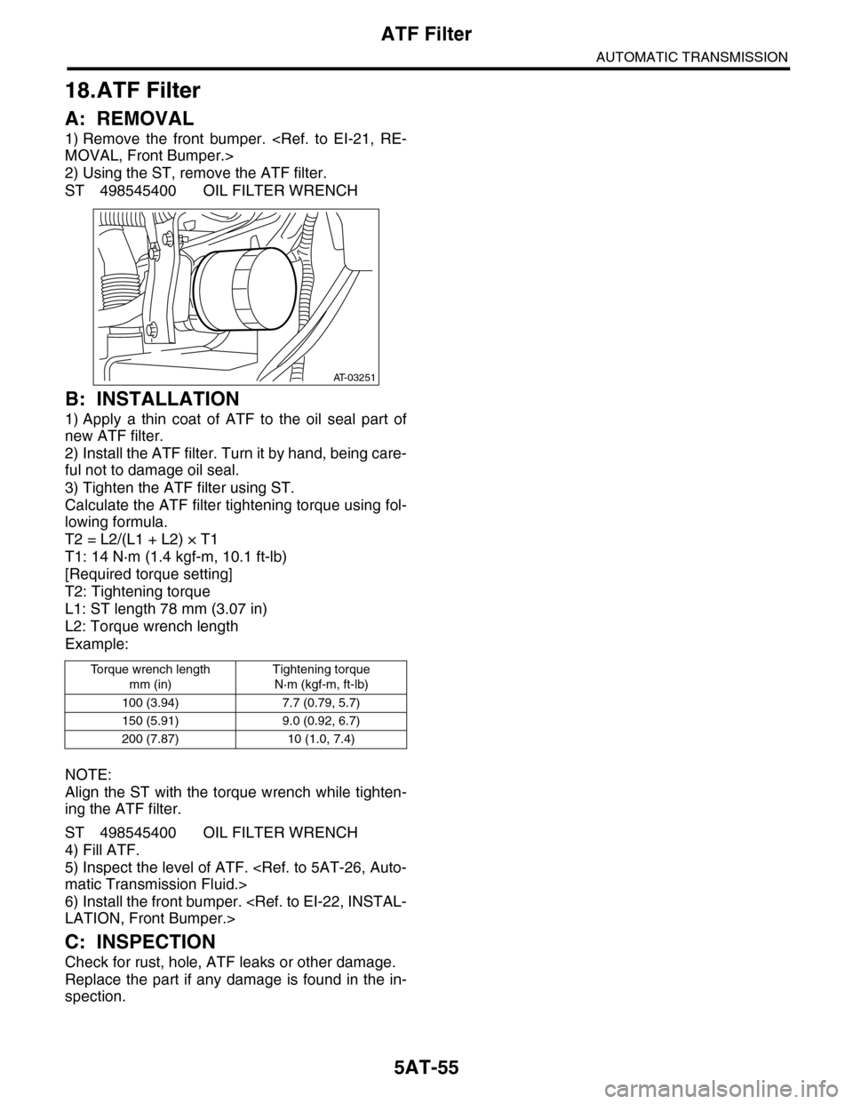
2) Using the ST, remove the ATF filter.
ST 498545400 OIL FILTER WRENCH
B: INSTALLATION
1) Apply a thin coat of ATF to the oil seal part of
new ATF filter.
2) Install the ATF filter. Turn it by hand, being care-
ful not to damage oil seal.
3) Tighten the ATF filter using ST.
Calculate the ATF filter tightening torque using fol-
lowing formula.
T2 = L2/(L1 + L2) × T1
T1: 14 N·m (1.4 kgf-m, 10.1 ft-lb)
[Required torque setting]
T2: Tightening torque
L1: ST length 78 mm (3.07 in)
L2: Torque wrench length
Example:
NOTE:
Align the ST with the torque wrench while tighten-
ing the ATF filter.
ST 498545400 OIL FILTER WRENCH
4) Fill ATF.
5) Inspect the level of ATF.
matic Transmission Fluid.>
6) Install the front bumper.
LATION, Front Bumper.>
C: INSPECTION
Check for rust, hole, ATF leaks or other damage.
Replace the part if any damage is found in the in-
spection.
To r q u e w r e n c h l e n g t h
mm (in)
Tightening torque
N·m (kgf-m, ft-lb)
100 (3.94) 7.7 (0.79, 5.7)
150 (5.91) 9.0 (0.92, 6.7)
200 (7.87) 10 (1.0, 7.4)
AT-03251
Page 2098 of 2453
5AT-82
Drive Pinion Shaft Assembly
AUTOMATIC TRANSMISSION
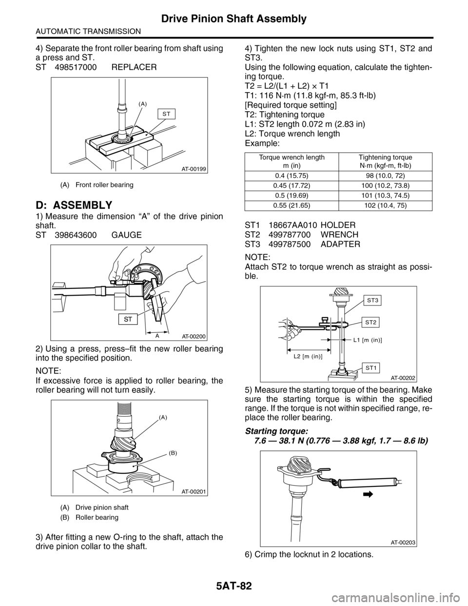
4) Separate the front roller bearing from shaft using
a press and ST.
ST 498517000 REPLACER
D: ASSEMBLY
1) Measure the dimension “A” of the drive pinion
shaft.
ST 398643600 GAUGE
2) Using a press, press–fit the new roller bearing
into the specified position.
NOTE:
If excessive force is applied to roller bearing, the
roller bearing will not turn easily.
3) After fitting a new O-ring to the shaft, attach the
drive pinion collar to the shaft.
4) Tighten the new lock nuts using ST1, ST2 and
ST3.
Using the following equation, calculate the tighten-
ing torque.
T2 = L2/(L1 + L2) × T1
T1: 116 N·m (11.8 kgf-m, 85.3 ft-lb)
[Required torque setting]
T2: Tightening torque
L1: ST2 length 0.072 m (2.83 in)
L2: Torque wrench length
Example:
ST1 18667AA010 HOLDER
ST2 499787700 WRENCH
ST3 499787500 ADAPTER
NOTE:
Attach ST2 to torque wrench as straight as possi-
ble.
5) Measure the starting torque of the bearing. Make
sure the starting torque is within the specified
range. If the torque is not within specified range, re-
place the roller bearing.
Starting torque:
7.6 — 38.1 N (0.776 — 3.88 kgf, 1.7 — 8.6 lb)
6) Crimp the locknut in 2 locations.
(A) Front roller bearing
(A) Drive pinion shaft
(B) Roller bearing
AT-00199
(A)
ST
AAT-00200
AT-00201
(B)
(A)
To r q u e w r e n c h l e n g t h
m (in)
Tightening torque
N·m (kgf-m, ft-lb)
0.4 (15.75) 98 (10.0, 72)
0.45 (17.72) 100 (10.2, 73.8)
0.5 (19.69) 101 (10.3, 74.5)
0.55 (21.65) 102 (10.4, 75)
ST1
AT-00202
L1 [m (in)]
L2 [m (in)]
ST2
ST3
AT-00203