2009 SUBARU TRIBECA light
[x] Cancel search: lightPage 751 of 2453

BR-37
Stop Light Switch
BRAKE
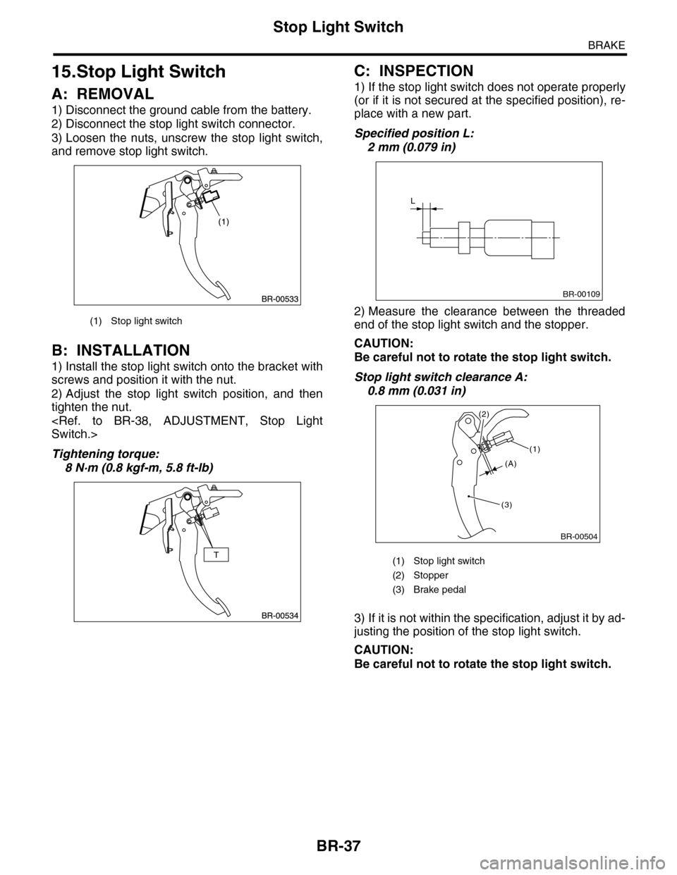
15.Stop Light Switch
A: REMOVAL
1) Disconnect the ground cable from the battery.
2) Disconnect the stop light switch connector.
3) Loosen the nuts, unscrew the stop light switch,
and remove stop light switch.
B: INSTALLATION
1) Install the stop light switch onto the bracket with
screws and position it with the nut.
2) Adjust the stop light switch position, and then
tighten the nut.
Tightening torque:
8 N·m (0.8 kgf-m, 5.8 ft-lb)
C: INSPECTION
1) If the stop light switch does not operate properly
(or if it is not secured at the specified position), re-
place with a new part.
Specified position L:
2 mm (0.079 in)
2) Measure the clearance between the threaded
end of the stop light switch and the stopper.
CAUTION:
Be careful not to rotate the stop light switch.
Stop light switch clearance A:
0.8 mm (0.031 in)
3) If it is not within the specification, adjust it by ad-
justing the position of the stop light switch.
CAUTION:
Be careful not to rotate the stop light switch.
(1) Stop light switch
(1) Stop light switch
(2) Stopper
(3) Brake pedal
L
BR-00109
BR-00504
(1)
(3)
(2)
(A)
Page 752 of 2453

BR-38
Stop Light Switch
BRAKE
D: ADJUSTMENT
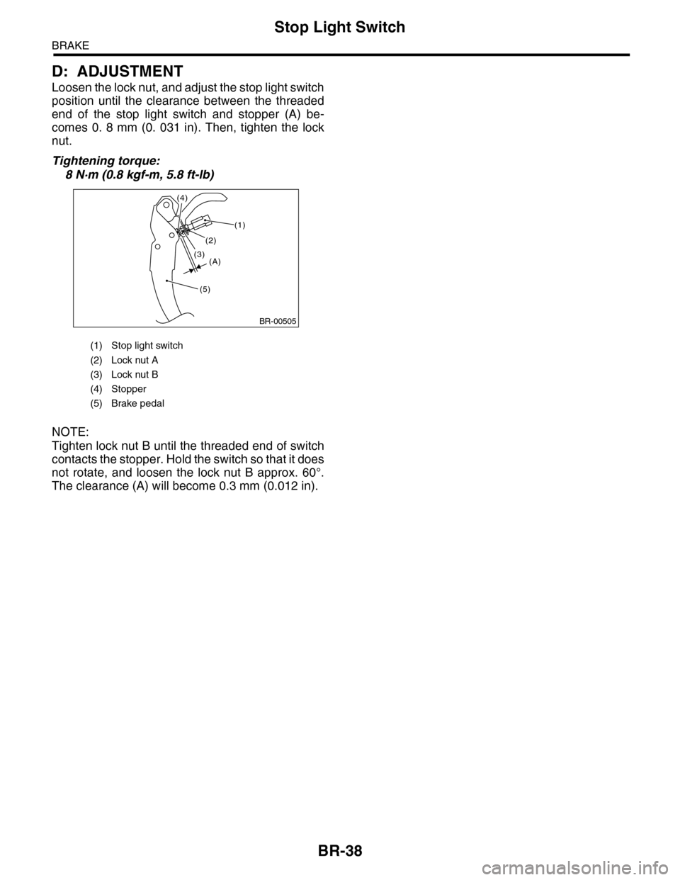
Loosen the lock nut, and adjust the stop light switch
position until the clearance between the threaded
end of the stop light switch and stopper (A) be-
comes 0. 8 mm (0. 031 in). Then, tighten the lock
nut.
Tightening torque:
8 N·m (0.8 kgf-m, 5.8 ft-lb)
NOTE:
Tighten lock nut B until the threaded end of switch
contacts the stopper. Hold the switch so that it does
not rotate, and loosen the lock nut B approx. 60°.
The clearance (A) will become 0.3 mm (0.012 in).
(1) Stop light switch
(2) Lock nut A
(3) Lock nut B
(4) Stopper
(5) Brake pedal
BR-00505
(1)
(5)
(4)
(A)(3)
(2)
Page 809 of 2453

DI-25
Rear Differential (VA–type)
DIFFERENTIALS
15) Perform the backlash adjustment between the
hypoid driven gear and drive pinion, and preload
adjustment of differential side bearing.
(1) Turn the drive pinion with ST for better fitting
of differential side bearing.
ST 498427200 FLANGE WRENCH
(2) Screw in the side holder LH until light con-
tact is made with ST.
ST 18630AA010 WRENCH
(3) Back off the holder on the hypoid driven
gear side by approx.1 and 1/2 teeth, and tighten
the other side holder by approx. 2 teeth (amount
that the hypoid driven gear is turned back (1
and 1/2) + 1/2 teeth).
[Back off amount of side (hypoid driven gear
side) holder + 1/2 tooth.] This + 1/2 tooth gives
preload.
(4) Temporarily tighten the lock plate.
NOTE:
Turn over the lock plate to shift the holder by 1/2
tooth.
(5) Measure the hypoid driven gear-to-drive
pinion backlash. Set the magnet base on differ-
ential carrier. Align the contact point of dial
gauge with tooth face of hypoid driven gear, and
move hypoid driven gear while holding drive
pinion still. Read the value indicated on dial
gauge.
NOTE:
If measured value of backlash is not within the
specified range, repeat the procedures for pinion
driven gear set backlash adjustment and the differ-
ential side bearing preload adjustment.
Backlash:
0.10 — 0.15 mm (0.0039 — 0.0059 in)
16) Put alignment marks on both the differential
carrier and holder. Remove the holder side at a
time.
Replace them in the original position after inserting
an O-ring and applying grease to the threaded por-
tion.
DI-00385
ST
ST
DI-00399
DI-00364
(A) Alignment mark
(B) Holder
DI-00172
DI-00386
(B)
(A)
Page 810 of 2453

DI-26
Rear Differential (VA–type)
DIFFERENTIALS
17) Tighten the bolt of lock plate to specified
torque.
Tightening torque:
25 N·m (2.5 kgf-m, 18.1 ft-lb)
18) Recheck the hypoid driven gear to pinion back-
lash.
Backlash:
0.10 — 0.15 mm (0.0039 — 0.0059 in)
19) Checking and adjusting the tooth contact of hy-
poid driven gear
(1) Apply an even coat of red lead on both sides
of three or four teeth on the hypoid driven gear.
Check the contact pattern after rotating the hy-
poid driven gear several revolutions back and
forth until a definite contact pattern appears on
the hypoid driven gear.
(2) When the contact pattern is not correct, re-
adjust.
NOTE:
Be sure to wipe off the red lead completely after the
adjustment is completed.
•Correct tooth contact
Check item: Tooth contact pattern is slightly
shifted towards the toe side under no-load rota-
tion. (When driving it will move toward the heel
side.)
•Face contact
Check item: Backlash is too large.
Contact pattern
Corrective action: Increase thickness of drive pin-
ion height adjusting washer in order to bring drive
pinion close to hypoid driven gear.
DI-00364
DI-00172
(A) Toe side
(B) Heel side
MT-01401
(A)
(B)
AT-00208
AT-00212
Page 812 of 2453

DI-28
Rear Differential (VA–type)
DIFFERENTIALS
23) Affix with the attachment clip so that the white
marking of the hose is within the range of Z (87°).
E: INSPECTION
Wash all the disassembled parts clean, and exam-
ine them for wear, damage or other defects. Repair
or replace the defective parts as necessary.
1) Hypoid driven gear and drive pinion
•If there is evidently an abnormal tooth contact,
find out the cause and adjust until the teeth contact
correctly. Replace the gear if there is an excessive
worn or an incapable adjustment.
•If crack, cutout or seizure is found, replace the
parts as a set. Slight damage of some teeth can be
corrected by oil stone or the like.
2) Side gear and pinion mate gear
•Replace the differential case assembly if cracks,
scoring or other defects are evident on tooth sur-
face.
3) Bearing
Replace if seizure, peeling, wear, rust, dragging
during rotation, noise or other defect is evident.
4) Oil seal
Replace if deformed or damaged, and at every dis-
assembling.
5) Differential carrier
Replace if the bearing bores are worn or damaged.
6) Differential case
Replace if its sliding surfaces are worn or cracked.
7) Companion flange
Replace if the oil seal lip contact surface shows
cracking.
1. HYPOID DRIVEN GEAR BACKLASH
Using a dial gauge, check the backlash of hypoid
driven gear.
Hypoid driven gear backlash:
0.10 — 0.15 mm (0.0039 — 0.0059 in)
If the hypoid driven gear backlash is not within the
specification, adjust the side bearing preload or re-
pair if necessary.
2. TOOTH CONTACT BETWEEN HYPOID
DRIVEN GEAR AND DRIVE PINION
Inspect the tooth contact between the hypoid driv-
en gear and drive pinion.
3. COMPANION FLANGE
1) If rust or dirt is attached to the companion flange,
remove them.
2) Set a dial gauge at a companion flange surface
(mating surface of propeller shaft and companion
flange), and then measure the companion flange
runout.
Limit of runout:
0.08 mm (0.003 in)
(1) 0 — 1 mm (0 — 0.04 in)
(2) Marking
DI-00478
B
B
A
A
Z
(1)
(2)
DI-00099
DI-00360
Page 843 of 2453

DS-26
Front Drive Shaft
DRIVE SHAFT SYSTEM
9) Remove the snap ring and trunnion.
CAUTION:
Be sure to wrap shaft splines with vinyl tape to
protect the boot from scratches.
10) Remove the PTJ boot.
NOTE:
The BJ is a non-disassembly part, so the axle dis-
assembly stops here.
D: ASSEMBLY
NOTE:
Use specified grease.
PTJ side:
NKG302 (Part No. 28395AG02A)
1) Place the PTJ boot at the center of shaft.
2) Align alignment marks and install the trunnion on
the shaft.
3) Install the snap ring to shaft.
CAUTION:
Confirm that the snap ring is completely fitted
in shaft groove.
4) Fill 100 to 110 g (3.53 to 3.88 oz) of specified
grease into the interior of PTJ outer race.
5) Apply a thin coat of specified grease to the roller
kit and trunnion.
6) Align alignment marks on roller kit and trunnion
and install the roller kit.
CAUTION:
Be careful with the roller kit position.
7) Align the alignment marks of the shaft and outer
race, and install the outer race.
8) Install the snap ring in the groove on PTJ outer
race.
CAUTION:
Pull the shaft lightly and assure that the snap
ring is completely fitted in the groove.
9) Apply an even coat of the specified grease 30 to
40 g (1.06 to 1.41 oz) to the entire inner surface of
boot.
10) Install the PTJ boot taking care not to twist it.
CAUTION:
•The large end of PTJ boot and the boot
groove shall be cleaned completely so as to be
free from grease and other substances.
•When installing PTJ boot, position outer race
of PTJ at center of its travel.
DS-00111
DS-00110
DS-00109
DS-00106
Page 848 of 2453

DS-31
Rear Drive Shaft
DRIVE SHAFT SYSTEM
10) Install the snap ring in the groove on the DOJ
outer race.
NOTE:
•Assure that the balls, cage and inner race are
completely fitted in the outer race of DOJ.
•Use care not to place the matched position of
snap ring in the ball groove of outer race.
•Pull the shaft lightly and assure that the circlip is
completely fitted in the groove.
11) Apply an even coat of the specified grease [20
to 30 g (0. 71 to 1. 06 oz)] to the entire inner surface
of boot. Also apply grease to the shaft.
12) Install the DOJ boot taking care not to twist it.
NOTE:
•The inside of the larger end of DOJ boot and the
boot groove shall be cleaned so as to be free from
grease and other substances.
•When installing the DOJ boot, position the outer
race of DOJ at center of the stroke.
13) Put a new band through the clip and wind twice
in the band groove of the boot.
14) Pinch the end of band with pliers. Hold the clip
and tighten securely.
NOTE:
When tightening boot, use care so that the air with-
in the boot is appropriate.
15) Tighten the band using the ST.
ST 925091000 BAND TIGHTENING TOOL
NOTE:
Tighten the band until it cannot be moved by hand.
16) Tap the clip with the punch provided at the end
of the ST.
ST 925091000 BAND TIGHTENING TOOL
NOTE:
Tap to an extent that the boot underneath is not
damaged.
17) Cut off the band with an allowance of about 10
mm (0.39 in) left from the clip and bend this allow-
ance over the clip.
NOTE:
Be careful so that the end of the band is in close
contact with clip.
18) Install the EBJ boot using the same procedures
as for the DOJ boot.
19) Extend and retract the DOJ repeatedly to pro-
vide an equal coating of grease.
E: INSPECTION
Check the removed parts for damage, wear, corro-
sion etc. Repair or replace if defective.
•DOJ (Double Offset Joint)
Check for seizure, corrosion, damage, wear and
excessive play.
•EBJ (high-efficiency compact ball fixed joint)
Check for seizure, corrosion, damage, wear and
excessive play.
•Shaft
Check for excessive bending, twisting, damage
and wear.
•Boot
Check for wear, warping, breakage and scratches.
•Grease
Check for discoloration and fluidity.
DS-00125
DS-00132
DS-00133
Page 879 of 2453

PB-8
Parking Brake Assembly (Rear Disc Brake)
PARKING BRAKE
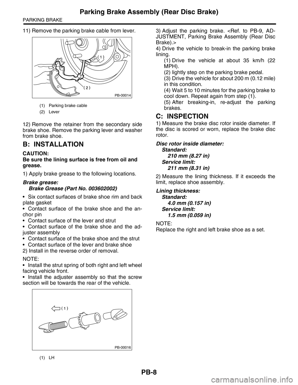
11) Remove the parking brake cable from lever.
12) Remove the retainer from the secondary side
brake shoe. Remove the parking lever and washer
from brake shoe.
B: INSTALLATION
CAUTION:
Be sure the lining surface is free from oil and
grease.
1) Apply brake grease to the following locations.
Brake grease:
Brake Grease (Part No. 003602002)
•Six contact surfaces of brake shoe rim and back
plate gasket
•Contact surface of the brake shoe and the an-
chor pin
•Contact surface of the lever and strut
•Contact surface of the brake shoe and the ad-
juster assembly
•Contact surface of the brake shoe and the strut
•Contact surface of the lever and brake shoe
2) Install in the reverse order of removal.
NOTE:
•Install the strut spring of both right and left wheel
facing vehicle front.
•Install the adjuster assembly so that the screw
section will be towards the rear of the vehicle.
3) Adjust the parking brake.
Brake).>
4) Drive the vehicle to break-in the parking brake
lining.
(1) Drive the vehicle at about 35 km/h (22
MPH).
(2) lightly step on the parking brake pedal.
(3) Drive the vehicle for about 200 m (0.12 mile)
in this condition.
(4) Wait 5 to 10 minutes for the parking brake to
cool down. Repeat again from step (1).
(5) After breaking-in, re-adjust the parking
brakes.
C: INSPECTION
1) Measure the brake disc rotor inside diameter. If
the disc is scored or worn, replace the brake disc
rotor.
Disc rotor inside diameter:
Standard:
210 mm (8.27 in)
Service limit:
211 mm (8.31 in)
2) Measure the lining thickness. If it exceeds the
limit, replace shoe assembly.
Lining thickness:
Standard:
4.0 mm (0.157 in)
Service limit:
1.5 mm (0.059 in)
NOTE:
Replace the right and left brake shoe as a set.
(1) Parking brake cable
(2) Lever
(1) LH
PB-00014
PB-00016