Page 684 of 2453
SL-55
Immobilizer Antenna
SECURITY AND LOCKS
26.Immobilizer Antenna
A: REMOVAL
1) Disconnect the ground cable from battery.
2) Remove the screws, and detach the upper col-
umn cover and lower column cover.
3) Remove the instrument panel lower cover.
to EI-36, REMOVAL, Instrument Panel Lower Cov-
er.>
4) Disconnect the immobilizer antenna connector
(A) and ignition switch lighting connector (B).
5) Loosen the screw and release the lock (D) at op-
posite side using flat-tip screwdriver (1), and then
detach the immobilizer antenna (C).
CAUTION:
Do not apply excessive force to remove the im-
mobilizer antenna and lock. Otherwise they
may be broken because those parts are the
products made of a plastic.
B: INSTALLATION
Install in the reverse order of removal.
SL-00258
(D)
(1)
SL-00315
(A)
(C)
(B)
Page 690 of 2453
SR-6
Glass Lid
SUNROOF/T-TOP/CONVERTIBLE TOP (SUNROOF)
D: FORCED DRIVE
If glass lid dose not operate or is not supplied with
power, move the glass lid using the hexagon
wrench *.
*: L shape universal purpose hexagon wrench
bolt width 4 mm (0.16 in)
1) Remove the spot map light.
MOVAL, Spot Map Light.>
2) Remove the sunroof opening trim.
3) Remove the sun visor clip.
4) Insert the hexagon wrench securely until it
touches the motor shaft edge.
CAUTION:
Make sure not to bend or wrinkle the roof trim
during work.
5) Turn the hexagon wrench, and move the glass
lid.
•Turning right, the glass lid open.
•Turning left, the glass lid close.
EI-00501
Page 692 of 2453

SR-8
Sunroof Motor
SUNROOF/T-TOP/CONVERTIBLE TOP (SUNROOF)
5. Sunroof Motor
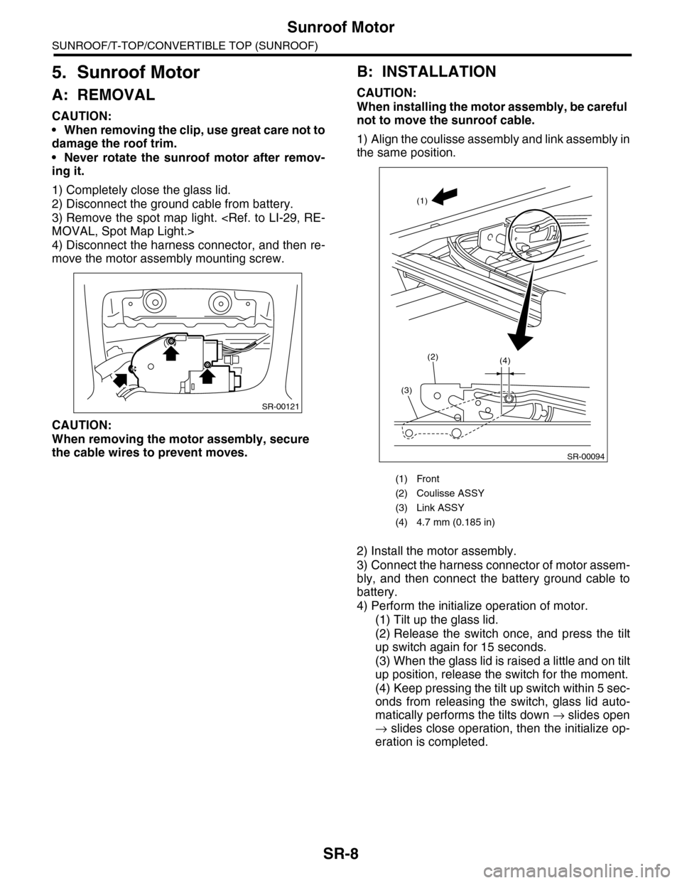
A: REMOVAL
CAUTION:
•When removing the clip, use great care not to
damage the roof trim.
•Never rotate the sunroof motor after remov-
ing it.
1) Completely close the glass lid.
2) Disconnect the ground cable from battery.
3) Remove the spot map light.
MOVAL, Spot Map Light.>
4) Disconnect the harness connector, and then re-
move the motor assembly mounting screw.
CAUTION:
When removing the motor assembly, secure
the cable wires to prevent moves.
B: INSTALLATION
CAUTION:
When installing the motor assembly, be careful
not to move the sunroof cable.
1) Align the coulisse assembly and link assembly in
the same position.
2) Install the motor assembly.
3) Connect the harness connector of motor assem-
bly, and then connect the battery ground cable to
battery.
4) Perform the initialize operation of motor.
(1) Tilt up the glass lid.
(2) Release the switch once, and press the tilt
up switch again for 15 seconds.
(3) When the glass lid is raised a little and on tilt
up position, release the switch for the moment.
(4) Keep pressing the tilt up switch within 5 sec-
onds from releasing the switch, glass lid auto-
matically performs the tilts down → slides open
→ slides close operation, then the initialize op-
eration is completed.
SR-00121
(1) Front
(2) Coulisse ASSY
(3) Link ASSY
(4) 4.7 mm (0.185 in)
SR-00094
(1)
(3)
(2)(4)
Page 694 of 2453
SR-10
Sunroof Switch
SUNROOF/T-TOP/CONVERTIBLE TOP (SUNROOF)
6. Sunroof Switch
A: REMOVAL
1) Disconnect the ground cable from battery.
2) Remove the spot map light lens (A) and sunroof
switch mounting screws (B).
3) Disconnect the harness connector, and then re-
move the sunroof switch.
B: INSTALLATION
Install in the reverse order of removal.
C: INSPECTION
Measure the sunroof switch resistance.
Switch position Terminal No. StandardConnector
No.
Open 1 and 3Less than
1 ΩR128
Close 3 and 4Less than
1 Ω
Tilt up 1 and 3Less than
1 ΩR187
Tilt down 3 and 4Less than
1 Ω
LI-00521
LI-00522
Page 705 of 2453

WW-10
Wiper Blade
WIPER AND WASHER SYSTEMS
4. Wiper Blade
A: REMOVAL
CAUTION:
When replacing the wiper blade, if standing up
the wiper arm, be sure to stand up the driver’s
side wiper arm first, and then passenger’s side
wiper arm next. Also, when putting the wiper
arms back, be sure to start with passenger’s
side first, then driver’s side next. Doing this in
the reverse order may result in the driver’s side
wiper blade hitting the passenger’s side wiper
arm and causing damage.
1. FRONT
While pushing the locking clip to the direction of the
arrow, pull out and remove the blade from the arm.
2. REAR
Turn the blade in the direction of arrow (A) and re-
move it from arm.
B: INSTALLATION
1) Install in the reverse order of removal.
2) Confirm that the clip is locked securely.
C: DISASSEMBLY
1. FRONT
Pull side (A) of the wiper rubber stopper and re-
move the rubber from the blade assembly.
2. REAR
Pull the wiper rubber top slightly from stopper (A)
and pull out completely.
WW-00354
(A) Turn the wiper blade.
(1) Wiper arm
(2) Wiper blade
(3) Wiper blade attachment section
(1)
(2)
(3)(A)WW-00207
WW-00009
WW-00143
(A)
Page 723 of 2453
BR-9
General Description
BRAKE
7. BRAKE PEDAL
(1) Brake pedal ASSY Tightening torque: N·m (kgf-m, ft-lb)
(2) Stop light switch T1: 8 (0.8, 5.8)
(3) Brake pedal pad T2: 18 (1.8, 13.0)
BR-00338
T2
T1
T2T1
(1)
(2)
(3)
Page 741 of 2453

BR-27
Brake Booster
BRAKE
B: INSTALLATION
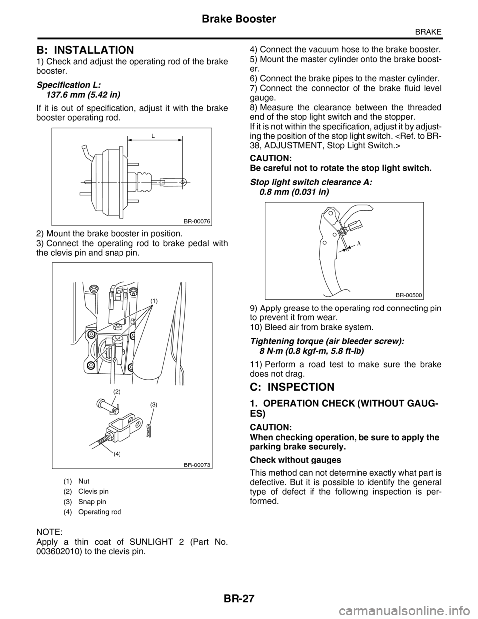
1) Check and adjust the operating rod of the brake
booster.
Specification L:
137.6 mm (5.42 in)
If it is out of specification, adjust it with the brake
booster operating rod.
2) Mount the brake booster in position.
3) Connect the operating rod to brake pedal with
the clevis pin and snap pin.
NOTE:
Apply a thin coat of SUNLIGHT 2 (Part No.
003602010) to the clevis pin.
4) Connect the vacuum hose to the brake booster.
5) Mount the master cylinder onto the brake boost-
er.
6) Connect the brake pipes to the master cylinder.
7) Connect the connector of the brake fluid level
gauge.
8) Measure the clearance between the threaded
end of the stop light switch and the stopper.
If it is not within the specification, adjust it by adjust-
ing the position of the stop light switch.
38, ADJUSTMENT, Stop Light Switch.>
CAUTION:
Be careful not to rotate the stop light switch.
Stop light switch clearance A:
0.8 mm (0.031 in)
9) Apply grease to the operating rod connecting pin
to prevent it from wear.
10) Bleed air from brake system.
Tightening torque (air bleeder screw):
8 N·m (0.8 kgf-m, 5.8 ft-lb)
11) Perform a road test to make sure the brake
does not drag.
C: INSPECTION
1. OPERATION CHECK (WITHOUT GAUG-
ES)
CAUTION:
When checking operation, be sure to apply the
parking brake securely.
Check without gauges
This method can not determine exactly what part is
defective. But it is possible to identify the general
type of defect if the following inspection is per-
formed.
(1) Nut
(2) Clevis pin
(3) Snap pin
(4) Operating rod
L
BR-00076
(1)
(3)
(4)
(2)
BR-00073
BR-00500
A
Page 750 of 2453

BR-36
Brake Pedal
BRAKE
14.Brake Pedal
A: REMOVAL
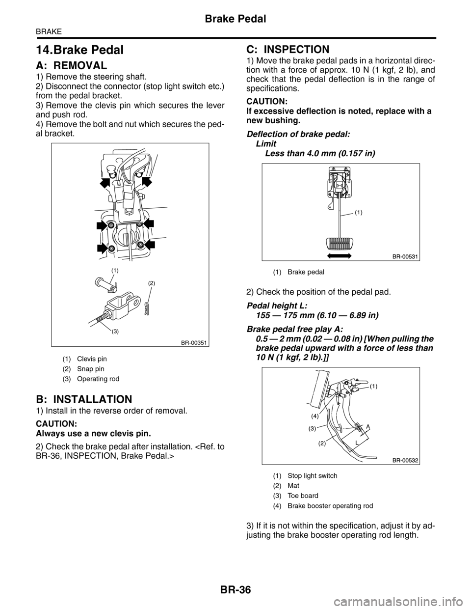
1) Remove the steering shaft.
2) Disconnect the connector (stop light switch etc.)
from the pedal bracket.
3) Remove the clevis pin which secures the lever
and push rod.
4) Remove the bolt and nut which secures the ped-
al bracket.
B: INSTALLATION
1) Install in the reverse order of removal.
CAUTION:
Always use a new clevis pin.
2) Check the brake pedal after installation.
BR-36, INSPECTION, Brake Pedal.>
C: INSPECTION
1) Move the brake pedal pads in a horizontal direc-
tion with a force of approx. 10 N (1 kgf, 2 lb), and
check that the pedal deflection is in the range of
specifications.
CAUTION:
If excessive deflection is noted, replace with a
new bushing.
Deflection of brake pedal:
Limit
Less than 4.0 mm (0.157 in)
2) Check the position of the pedal pad.
Pedal height L:
155 — 175 mm (6.10 — 6.89 in)
Brake pedal free play A:
0.5 — 2 mm (0.02 — 0.08 in) [When pulling the
brake pedal upward with a force of less than
10 N (1 kgf, 2 lb).]]
3) If it is not within the specification, adjust it by ad-
justing the brake booster operating rod length.
(1) Clevis pin
(2) Snap pin
(3) Operating rod
(2)
(3)
(1)
BR-00351
(1) Brake pedal
(1) Stop light switch
(2) Mat
(3) Toe board
(4) Brake booster operating rod