2009 NISSAN LATIO oil type
[x] Cancel search: oil typePage 3133 of 4331
Trouble Diagnosis Introduction "
(Type 1) or
EC-1089, " Trouble Diagnosis Introduction " (Type 2).
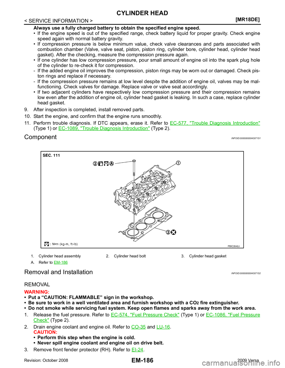
Component INFOID:0000000004307151
Removal and Installation INFOID:0000000004307152
REMOVAL
WARNING:
• Put a “CAUTION: FLAMMABLE” sign in the workshop.
• Be sure to work in a well ventilate d area and furnish workshop with a CO
2 fire extinguisher.
• Do not smoke while servicing fuel system. Keep open flames and sparks away from the work area.
1. Release the fuel pressure. Refer to EC-574, " Fuel Pressure Check " (Type 1) or
EC-1086, " Fuel Pressure
Check " (Type 2).
2. Drain engine coolant and engine oil. Refer to CO-35 and
LU-16 .
CAUTION:
• Perform this step when the engine is cold.
• Never spill engine coolant an d engine oil on drive belt.
3. Remove front fender protector (RH). Refer to EI-24 .
1. Cylinder head assembly 2. Cylinder head bolt 3. Cylinder head gasket
A. Refer to EM-186
Page 3143 of 4331
Garage Jack and
Safety Stand and 2-Pole Lift " .
REMOVAL
Remove the engine and the transaxle assembly from t he vehicle downward. Separate the engine and the tran-
saxle.
1. Remove engine undercover.
2. Drain engine coolant from radiator. Refer to CO-35, " Changing Engine Coolant " .
CAUTION:
• Perform this step when the engine is cold.
• Do not spill engine coolant on drive belt.
3. Remove front fender protector (RH and LH). Refer to EI-24 .
4. Remove exhaust front tube. Refer to EX-9 .
5. Remove drive shafts (LH and RH) from steering knuckle. Refer to FAX-9 .
6. Remove transaxle joint bolts which pierce at oil pan (upper) lower rear side. Refer to AT-232 (A/T models),
CVT-182 or
CVT-354 (CVT models) or
MT-58 (M/T models).
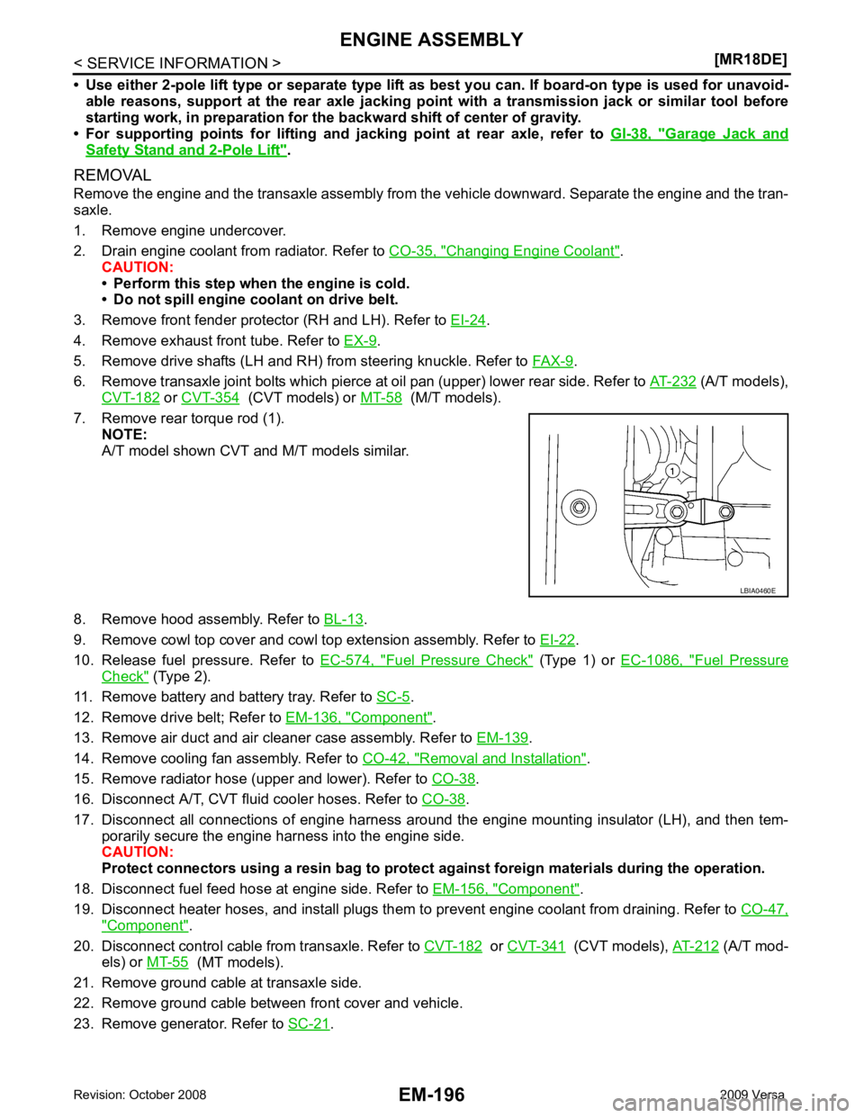
7. Remove rear torque rod (1). NOTE:
A/T model shown CVT and M/T models similar.
8. Remove hood assembly. Refer to BL-13 .
9. Remove cowl top cover and cowl top extension assembly. Refer to EI-22 .
10. Release fuel pressure. Refer to EC-574, " Fuel Pressure Check " (Type 1) or
EC-1086, " Fuel Pressure
Check " (Type 2).
11. Remove battery and battery tray. Refer to SC-5 .
12. Remove drive belt; Refer to EM-136, " Component " .
13. Remove air duct and air cleaner case assembly. Refer to EM-139 .
14. Remove cooling fan assembly. Refer to CO-42, " Removal and Installation " .
15. Remove radiator hose (upper and lower). Refer to CO-38 .
16. Disconnect A/T, CVT fluid cooler hoses. Refer to CO-38 .
17. Disconnect all connections of engine harness around the engine mounting insulator (LH), and then tem- porarily secure the engine harness into the engine side.
CAUTION:
Protect connectors using a resin bag to protect against foreign materials during the operation.
18. Disconnect fuel feed hose at engine side. Refer to EM-156, " Component " .
19. Disconnect heater hoses, and install plugs them to prevent engine coolant from draining. Refer to CO-47," Component " .
20. Disconnect control cable from transaxle. Refer to CVT-182 or
CVT-341 (CVT models),
AT-212 (A/T mod-
els) or MT-55 (MT models).
21. Remove ground cable at transaxle side.
22. Remove ground cable between front cover and vehicle.
23. Remove generator. Refer to SC-21 .
Page 3174 of 4331
EM
NP
O
SERVICE DATA AND SPECIFICATIONS (SDS)
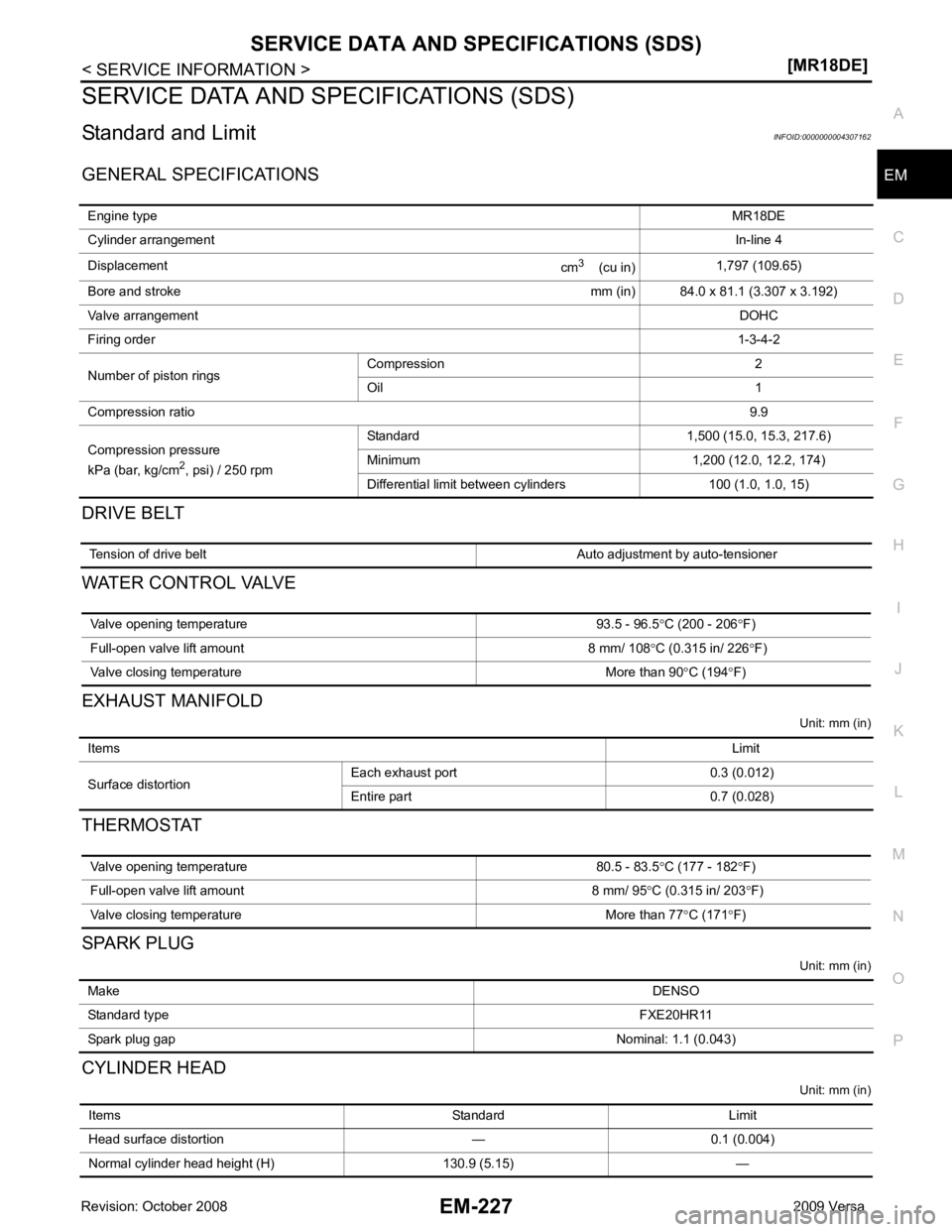
Standard and Limit INFOID:0000000004307162
GENERAL SPECIFICATIONS
DRIVE BELT
WATER CONTROL VALVE
EXHAUST MANIFOLD Unit: mm (in)
THERMOSTAT
SPARK PLUG Unit: mm (in)
CYLINDER HEAD Unit: mm (in)
Engine type
MR18DE
Cylinder arrangement In-line 4
Displacement cm3
(cu in) 1,797 (109.65)
Bore and stroke mm (in) 84.0 x 81.1 (3.307 x 3.192)
Valve arrangement DOHC
Firing order 1-3-4-2
Number of piston rings Compression 2
Oil 1
Compression ratio 9.9
Compression pressure
kPa (bar, kg/cm 2
, psi) / 250 rpm Standard 1,500 (15.0, 15.3, 217.6)
Minimum 1,200 (12.0, 12.2, 174)
Differential limit between cylinders 100 (1.0, 1.0, 15) Tension of drive belt Auto adjustment by auto-tensioner
Valve opening temperature 93.5 - 96.5
°C (200 - 206 °F)
Full-open valve lift amount 8 mm/ 108 °C (0.315 in/ 226 °F)
Valve closing temperature More than 90 °C (194 °F) Items
Limit
Surface distortion Each exhaust port 0.3 (0.012)
Entire part 0.7 (0.028) Valve opening temperature 80.5 - 83.5
°C (177 - 182 °F)
Full-open valve lift amount 8 mm/ 95 °C (0.315 in/ 203 °F)
Valve closing temperature More than 77 °C (171 °F) Make
DENSO
Standard type FXE20HR11
Spark plug gap Nominal: 1.1 (0.043)Items Standard Limit
Head surface distortion — 0.1 (0.004)
Normal cylinder head height (H) 130.9 (5.15) —
Page 3241 of 4331

FSU
N
O P
FRONT SUSPENSION ASSEMBLY
On-Vehicle Inspection and Service INFOID:0000000004305863
Make sure the mounting conditions (looseness, back lash) of each component and component conditions
(wear, damage) are normal.
INSPECTION OF LOWER BALL JOINT END PLAY 1. Set front wheels in a straight-ahead position. Do not depress brake pedal.
2. Place an iron bar or similar tool bet ween transverse link and steering knuckle.
3. Measure axial end play by prying it up and down.
CAUTION:
Be careful not to damage ball joint boot. Do not damage the installation position by applying
excessive force.
STRUT INSPECTION Check for oil leakage, damage and replace as necessary.
Wheel Alignment Inspection INFOID:0000000004305864
PRELIMINARY INSPECTION WARNING:
Always adjust the alignment with the vehicle on a flat surface.
NOTE:
If alignment is out of specification, inspect and r eplace any damaged or worn rear suspension parts before
making any adjustments.
1. Check and adjust the wheel alignment with the vehicle under unladen conditions. “Unladen conditions”
means that the fuel, coolant, and lubricant are full; and that the spare tire, jack, hand tools and mats are in
their designated positions.
2. Check the tires for incorrect air pressure and excessive wear.
3. Check the wheels for run out and damage. Refer to WT-6, " Inspection " .
4. Check the wheel bearing axial end play. Refer to FAX-6, " On-Vehicle Inspection and Service " .
5. Check the shock absorbers for leaks or damage.
6. Check each mounting point of the suspension components for any excessive looseness or damage.
7. Check each link, arm, and the suspension member for any damage.
8. Check the vehicle height. Refer to FSU-19, " Wheelarch Height (Unladen*) " .
GENERAL INFORMATION AND RECOMMENDATIONS 1. A Four-Wheel Thrust Alignment should be performed. • This type of alignment is re commended for any NISSAN vehicle.
• The four-wheel “thrust” process helps ensure that the vehicle is properly aligned and the steering wheel
is centered.
• The alignment machine itself should be ca pable of accepting any NISSAN vehicle.
• The alignment machine should be checked to ensure that it is level.
2. Make sure the alignment machine is properly calibrated. • Your alignment machine should be regularly calib rated in order to give correct information.
• Check with the manufacturer of your specific a lignment machine for their recommended Service/Cali-
bration Schedule.
THE ALIGNMENT PROCESS IMPORTANT: Use only the alignment specifications listed in this Service Manual. Refer to FSU-17, " Wheel
Alignment (Unladen*) " .
1. When displaying the alignment settings, many alignm ent machines use “indicators”: (Green/red, plus or
minus, Go/No Go). Do NOT use these indicators.
• The alignment specifications programmed into your alignment machine that operate these indicators
may not be correct. Axial end play : 0 mm (0 in)
Page 3286 of 4331
GI
N
O P
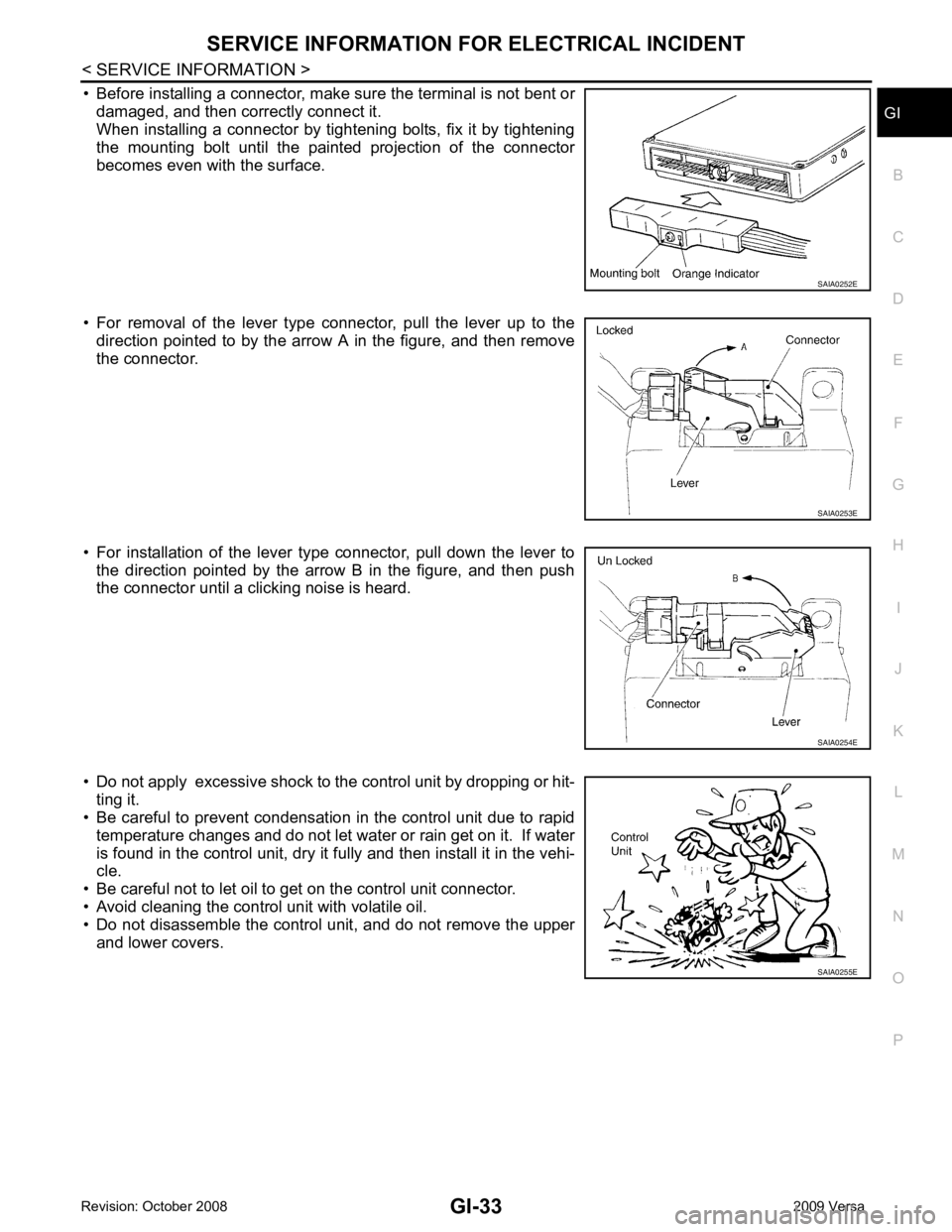
• Before installing a connector, make sure the terminal is not bent or
damaged, and then correctly connect it.
When installing a connector by tightening bolts, fix it by tightening
the mounting bolt until the painted projection of the connector
becomes even with the surface.
• For removal of the lever type connector, pull the lever up to the direction pointed to by the arrow A in the figure, and then remove
the connector.
• For installation of the lever type connector, pull down the lever to the direction pointed by the arrow B in the figure, and then push
the connector until a clicking noise is heard.
• Do not apply excessive shock to the control unit by dropping or hit- ting it.
• Be careful to prevent condensation in the control unit due to rapid
temperature changes and do not let water or rain get on it. If water
is found in the control unit, dry it fully and then install it in the vehi-
cle.
• Be careful not to let oil to get on the control unit connector.
• Avoid cleaning the control unit with volatile oil.
• Do not disassemble the control unit, and do not remove the upper
and lower covers.
Page 3652 of 4331
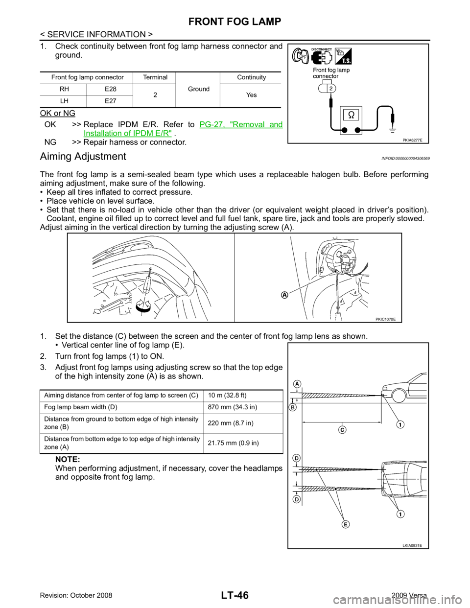
OK >> Replace IPDM E/R. Refer to
PG-27, " Removal and
Installation of IPDM E/R " .
NG >> Repair harness or connector.
Aiming Adjustment INFOID:0000000004306569
The front fog lamp is a semi-sealed beam type which uses a replaceable halogen bulb. Before performing
aiming adjustment, make sure of the following.
• Keep all tires inflated to correct pressure.
• Place vehicle on level surface.
• Set that there is no-load in vehicle other than the driv er (or equivalent weight placed in driver’s position).
Coolant, engine oil filled up to correct level and full fuel tank, spare tire, jack and tools are properly stowed.
Adjust aiming in the vertical direct ion by turning the adjusting screw (A).
1. Set the distance (C) between the screen and the center of front fog lamp lens as shown. • Vertical center line of fog lamp (E).
2. Turn front fog lamps (1) to ON.
3. Adjust front fog lamps using adjusting screw so that the top edge of the high intensity zone (A) is as shown.
NOTE:
When performing adjustment, if necessary, cover the headlamps
and opposite front fog lamp.
Front fog lamp connector Terminal
Ground Continuity
RH E28 2 Yes
LH E27
Page 3721 of 4331
LT
N
O P
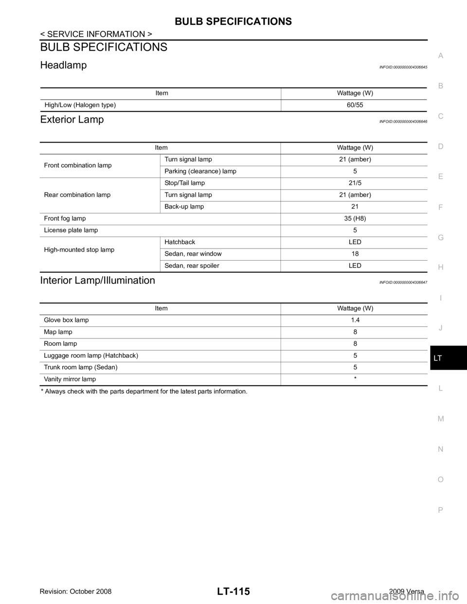
BULB SPECIFICATIONS
Headlamp INFOID:0000000004306645
Exterior Lamp INFOID:0000000004306646
Interior Lamp/Illumination INFOID:0000000004306647
* Always check with the parts department for the latest parts information. Item Wattage (W)
High/Low (Halogen type) 60/55Item Wattage (W)
Front combination lamp Turn signal lamp 21 (amber)
Parking (clearance) lamp 5
Rear combination lamp Stop/Tail lamp 21/5
Turn signal lamp 21 (amber)
Back-up lamp 21
Front fog lamp 35 (H8)
License plate lamp 5
High-mounted stop lamp Hatchback LED
Sedan, rear window 18
Sedan, rear spoiler LED Item Wattage (W)
Glove box lamp 1.4
Map lamp 8
Room lamp 8
Luggage room lamp (Hatchback) 5
Trunk room lamp (Sedan) 5
Vanity mirror lamp *
Page 3752 of 4331
MA
N
O P
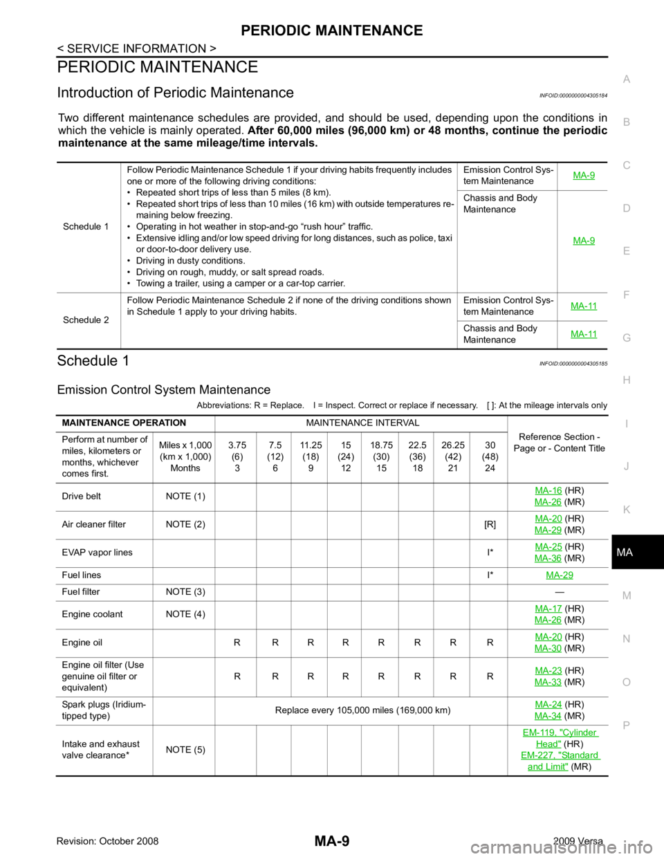
PERIODIC MAINTENANCE
Introduction of Periodic Maintenance INFOID:0000000004305184
Two different maintenance schedules are provi ded, and should be used, depending upon the conditions in
which the vehicle is mainly operated. After 60,000 miles (96,000 km) or 48 months, continue the periodic
maintenance at the same mileage/time intervals.
Schedule 1 INFOID:0000000004305185
Emission Control System Maintenance Abbreviations: R = Replace. I = Inspect. Correct or r eplace if necessary. [ ]: At the mileage intervals only
Schedule 1
Follow Periodic Maintenance Schedule 1 if your driving habits frequently includes
one or more of the following driving conditions:
• Repeated short trips of less than 5 miles (8 km).
• Repeated short trips of less than 10 miles (16 km) with outside temperatures re- maining below freezing.
• Operating in hot weather in stop-and-go “rush hour” traffic.
• Extensive idling and/or low speed driving for long distances, such as police, taxi or door-to-door delivery use.
• Driving in dusty conditions.
• Driving on rough, muddy, or salt spread roads.
• Towing a trailer, using a camper or a car-top carrier. Emission Control Sys-
tem Maintenance MA-9 Chassis and Body
Maintenance
MA-9Schedule 2
Follow Periodic Maintenance Schedule 2 if none of the driving conditions shown
in Schedule 1 apply to your driving habits. Emission Control Sys-
tem Maintenance MA-11 Chassis and Body
Maintenance MA-11 (HR)
MA-26 (MR)
Air cleaner filter NOTE (2) [R]MA-20 (HR)
MA-29 (MR)
EVAP vapor lines I*MA-25 (HR)
MA-36 (MR)
Fuel lines I*MA-29 Fuel filter NOTE (3)
—
Engine coolant NOTE (4) MA-17 (HR)
MA-26 (MR)
Engine oil R R R R R R R R MA-20 (HR)
MA-30 (MR)
Engine oil filter (Use
genuine oil filter or
equivalent) R R R R R R R R
MA-23 (HR)
MA-33 (MR)
Spark plugs (Iridium-
tipped type) Replace every 105,000 miles (169,000 km)
MA-24 (HR)
MA-34 (MR)
Intake and exhaust
valve clearance* NOTE (5) EM-119, " Cylinder
Head " (HR)
EM-227, " Standard
and Limit " (MR)