Page 3896 of 4331

MTC
N
O P
PREPARATION
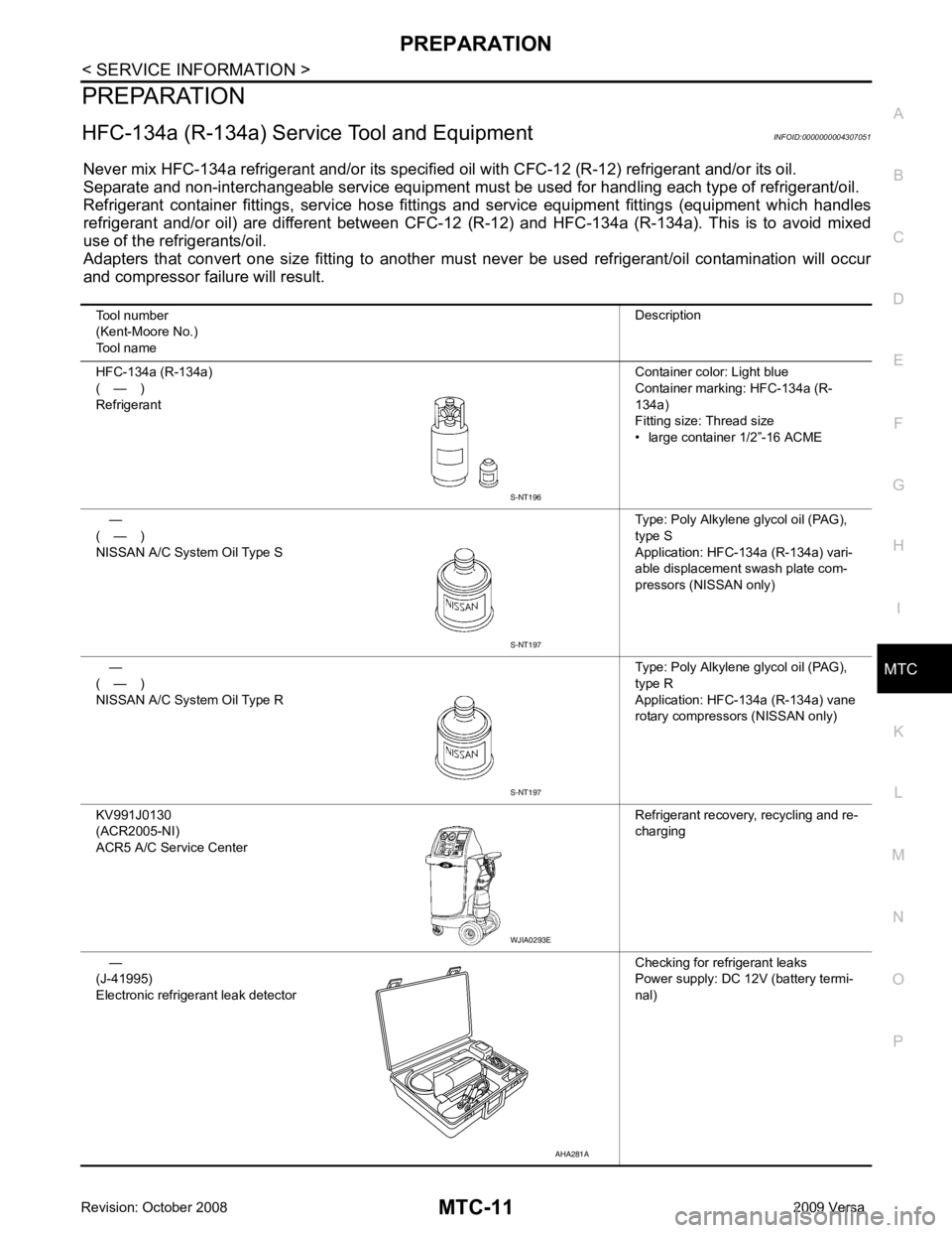
HFC-134a (R-134a) Servic e Tool and Equipment INFOID:0000000004307051
Never mix HFC-134a refrigerant and/or its specified oil with CFC-12 (R-12) refrigerant and/or its oil.
Separate and non-interchangeable service equipment must be used for handling each type of refrigerant/oil.
Refrigerant container fittings, service hose fittings and service equipment fittings (equipment which handles
refrigerant and/or oil) are different between CFC-12 (R-12) and HFC-134a (R-134a). This is to avoid mixed
use of the refrigerants/oil.
Adapters that convert one size fitting to another must never be used refrigerant/oil contamination will occur
and compressor failure will result.
Tool number
(Kent-Moore No.)
Tool name Description
HFC-134a (R-134a)
( — )
Refrigerant Container color: Light blue
Container marking: HFC-134a (R-
134a)
Fitting size: Thread size
• large container 1/2”-16 ACME
—
( — )
NISSAN A/C System Oil Type S Type: Poly Alkylene glycol oil (PAG),
type S
Application: HFC-134a (R-134a) vari-
able displacement swash plate com-
pressors (NISSAN only)
—
( — )
NISSAN A/C System Oil Type R Type: Poly Alkylene glycol oil (PAG),
type R
Application: HFC-134a (R-134a) vane
rotary compressors (NISSAN only)
KV991J0130
(ACR2005-NI)
ACR5 A/C Se rvice Center Refrigerant recovery, recycling and re-
charging
—
(J-41995)
Electronic refrigerant leak detector Checking for refrigerant leaks
Power supply: DC 12V (battery termi-
nal) S-NT197
WJIA0293E
AHA281A
Page 3902 of 4331

MTC
N
O P
OIL
Maintenance of Oil Qu antity in Compressor INFOID:0000000004307056
The oil in the compressor circulates through the system with the refrigerant. Add oil to compressor when
replacing any component or after a lar ge refrigerant leakage occurred. It is important to maintain the specified
amount.
If oil quantity is not maintained properly , the following malfunctions may result:
• Lack of oil: May lead to a seized compressor.
• Excessive oil: Inadequate cooling (thermal exchange interference)
OIL
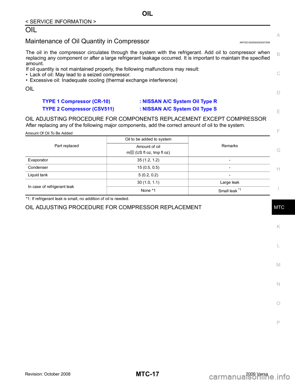
OIL ADJUSTING PROCEDURE FOR COMPONENTS REPLACEMENT EXCEPT COMPRESSOR After replacing any of the following major component s, add the correct amount of oil to the system.
Amount Of Oil To Be Added
*1: If refrigerant leak is small, no addition of oil is needed.
OIL ADJUSTING PROCEDURE FOR COMPRESSOR REPLACEMENT TYPE 1 Compressor (CR-10) : NISSAN A/C System Oil Type R
TYPE 2 Compressor (CSV511) : NI SSAN A/C System Oil Type S
Part replaced Oil to be added to system
Remarks
Amount of oil
m (US fl oz, Imp fl oz)
Evaporator 35 (1.2, 1.2) -
Condenser 15 (0.5, 0.5) -
Liquid tank 5 (0.2, 0.2) -
In case of refrigerant leak 30 (1.0, 1.1) Large leak
None *1 Small leak *1
Page 3942 of 4331
MTC
N
O P
THERMO CONTROL AMPLIFIER
Removal and Installation INFOID:0000000004307078
NOTE:
Only MR18DE - TYPE 2 systems are equipped with a thermo control amplifier.
REMOVAL 1. Remove evaporator. Refer to MTC-85, " Removal and Installation of Evaporator " .
CAUTION:
Cap or wrap the joint of the pipe with suitable ma terial such as vinyl tape to avoid the entry of air.
2. Mark the mounting position of the thermo control amp. and then remove thermo control amp. (1) from evaporator (2).
INSTALLATION Installation is in the reverse order of removal.
CAUTION:
• Replace O-rings for A/C piping with new on es, and apply compressor oil when installing.
• Install the thermo control amp. at the mark made during removal of the thermo control amp.
• When recharging refrigerant, check for leaks.
Page 3944 of 4331

MTC
N
O P
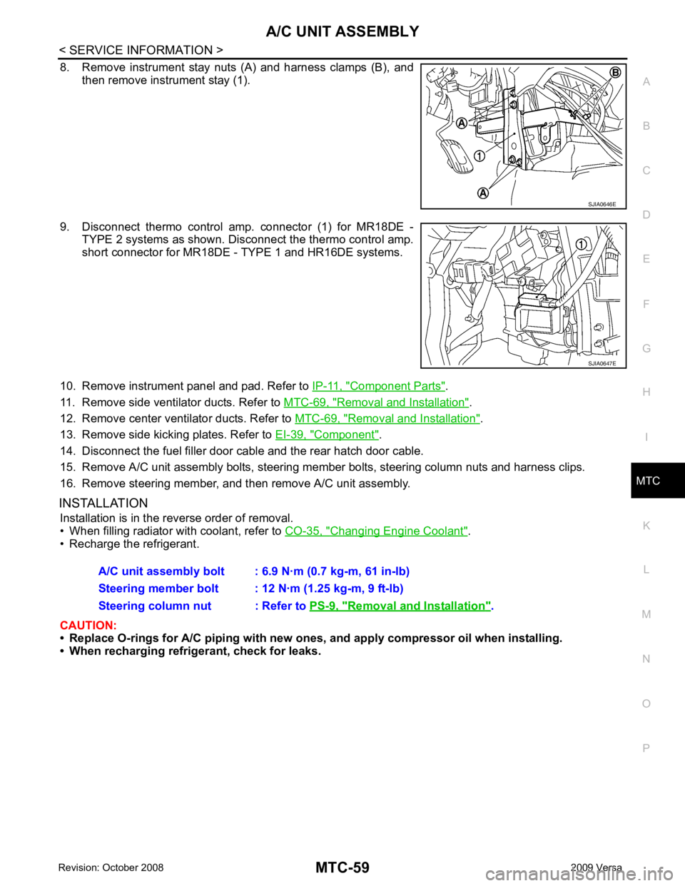
8. Remove instrument stay nuts (A) and harness clamps (B), and
then remove instrument stay (1).
9. Disconnect thermo control amp. connector (1) for MR18DE - TYPE 2 systems as shown. Disconnect the thermo control amp.
short connector for MR18DE - TYPE 1 and HR16DE systems.
10. Remove instrument panel and pad. Refer to IP-11, " Component Parts " .
11. Remove side ventilator ducts. Refer to MTC-69, " Removal and Installation " .
12. Remove center ventilator ducts. Refer to MTC-69, " Removal and Installation " .
13. Remove side kicking plates. Refer to EI-39, " Component " .
14. Disconnect the fuel filler door cable and the rear hatch door cable.
15. Remove A/C unit assembly bolts, steering member bolts, steering column nuts and harness clips.
16. Remove steering member, and then remove A/C unit assembly.
INSTALLATION Installation is in the reverse order of removal.
• When filling radiator with coolant, refer to CO-35, " Changing Engine Coolant " .
• Recharge the refrigerant.
CAUTION:
• Replace O-rings for A/C piping with new on es, and apply compressor oil when installing.
• When recharging refrigerant, check for leaks. Removal and Installation " .
Page 3975 of 4331
Application MR18DE - TYPE
1 and HR16DE MR18DE - TYPE 2
Compressor model Calsonic Kansei make CR-10 Calsonic Kansei make CSV511
Type NISSAN A/C System Oil Type R NISSAN A/C System Oil Type S
Capacity
m (US fl oz,
lmp fl oz) Total in system 120 (4.1, 4.2) 100 (3.4, 3.5)
Compressor (service
part) charging
amount Refer to
MTC-17, " Maintenance of Oil Quanti-
ty in Compressor " .
Refer to
MTC-17, " Maintenance of Oil
Quantity in Compressor " .
Type
HFC-134a (R-134a)
Capacity
kg (lb) 0.45
± 0.05 (0.99 ± 0.11)