2009 NISSAN LATIO oil type
[x] Cancel search: oil typePage 2990 of 4331
EM
NP
O
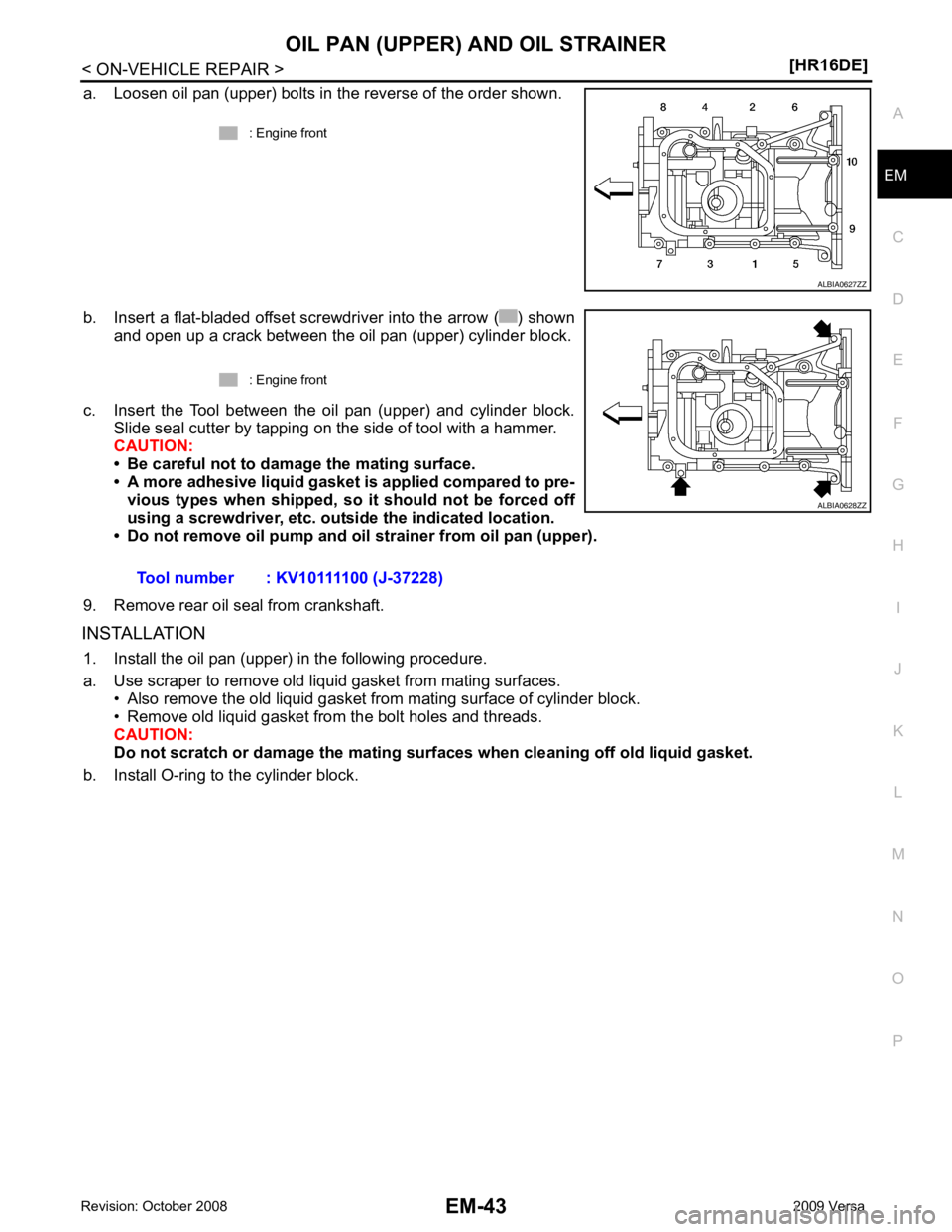
a. Loosen oil pan (upper) bolts in the reverse of the order shown.
b. Insert a flat-bladed offset screwdriver into the arrow ( ) shown and open up a crack between the oil pan (upper) cylinder block.
c. Insert the Tool between the oil pan (upper) and cylinder block. Slide seal cutter by tapping on the side of tool with a hammer.
CAUTION:
• Be careful not to damage the mating surface.
• A more adhesive liquid gasket is applied compared to pre-
vious types when shipped, so it should not be forced off
using a screwdriver, etc. ou tside the indicated location.
• Do not remove oil pump and oil strainer from oil pan (upper).
9. Remove rear oil seal from crankshaft.
INSTALLATION 1. Install the oil pan (upper) in the following procedure.
a. Use scraper to remove old liquid gasket from mating surfaces. • Also remove the old liquid gasket from mating surface of cylinder block.
• Remove old liquid gasket from the bolt holes and threads.
CAUTION:
Do not scratch or damage the mating su rfaces when cleaning off old liquid gasket.
b. Install O-ring to the cylinder block. : Engine front
Page 3040 of 4331
EM
NP
O
DISASSEMBLY AND ASSEMBLY
ENGINE STAND SETTING
Setting INFOID:0000000004784310
NOTE:
Explained here is how to disassemble with engine stand supporting transmission surface. When using differ-
ent type of engine stand, note with difference in steps and etc.
1. Remove the engine and the transaxle assembly from the vehicle, and separate the transaxle from the
engine. Refer to EM-88, " Exploded View " .
2. Remove clutch cover and clutch disc (if equipped). Refer to CL-15, " Removal and Installation " .
3. Remove flywheel or driveplate. • Secure flywheel or driveplate with Tool, and remove bolts.
CAUTION:
• Never disassemble flywheel.
• Never place flywheel or driveplate with signal plate facing down.
• When handling signal plate, take car e not to damage or scratch it.
• Handle signal plate in a manner that prevents it from becoming magnetized.
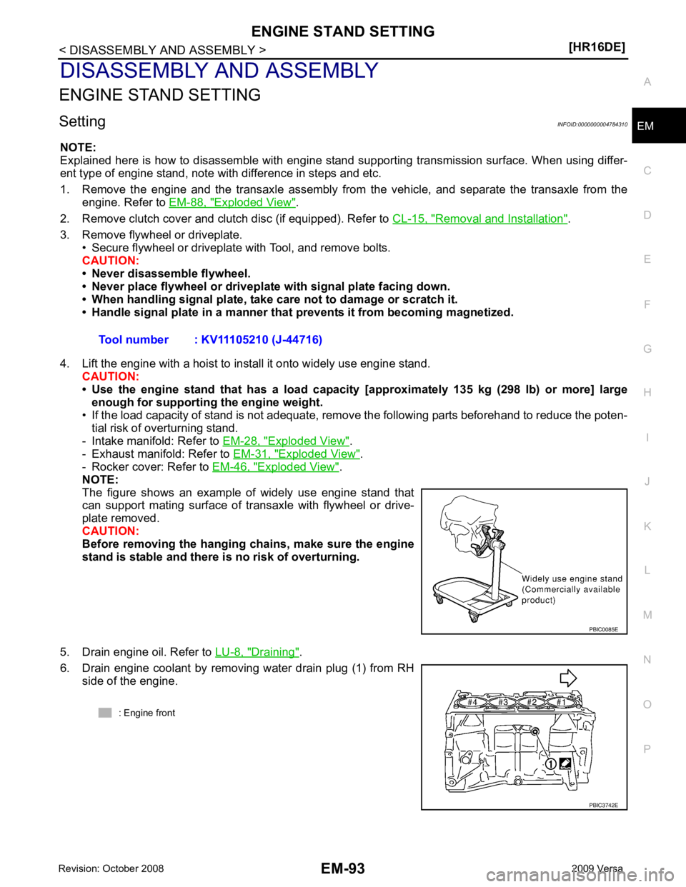
4. Lift the engine with a hoist to install it onto widely use engine stand. CAUTION:
• Use the engine stand that has a load capacity [approximately 135 kg (298 lb) or more] large
enough for supporting the engine weight.
• If the load capacity of stand is not adequate, remove the following parts beforehand to reduce the poten-
tial risk of overturning stand.
- Intake manifold: Refer to EM-28, " Exploded View " .
- Exhaust manifold: Refer to EM-31, " Exploded View " .
- Rocker cover: Refer to EM-46, " Exploded View " .
NOTE:
The figure shows an example of widely use engine stand that
can support mating surface of transaxle with flywheel or drive-
plate removed.
CAUTION:
Before removing the hanging chains, make sure the engine
stand is stable and there is no risk of overturning.
5. Drain engine oil. Refer to LU-8, " Draining " .
6. Drain engine coolant by removing water drain plug (1) from RH side of the engine. Tool number : KV11105210 (J-44716)
Page 3064 of 4331
EM
NP
O
*: When engine is cold.
Spark Plug INFOID:0000000004784324
SPARK PLUG (PLATINUM-TIPPED TYPE) Unit: mm (in)
Exhaust Manifold INFOID:0000000004784325
EXHAUST MANIFOLD Unit: mm (in)
Camshaft INFOID:0000000004784326
CAMSHAFT Unit: mm (in)
Location
Tension adjustment * Unit: N (kg, lb) Frequency adjustment * Unit: Hz
Used belt New beltUsed belt
New belt
Limit After adjusted Limit After adjusted
Drive belt With A/C models 500 (51.0, 112)
876 - 964
(89.4 - 98.3,
197 - 217) 1064 - 1152
(108.5 - 117.5,
239 - 259) 173 229 - 239 253.5 - 261.5
Without A/C models 500 (51.0, 112) 876 - 964
(89.4 - 98.3, 197 - 217) 1064 - 1152
(108.5 - 117.5, 239 - 259) 194 257.5 - 267.5 283 - 293Make
Denso
Standard type FXE20HE-11
Gap (Nominal) 1.1 (0.043)Items Limit
Surface distortion Exhaust manifold 0.3 (0.012) Items
Standard Limit
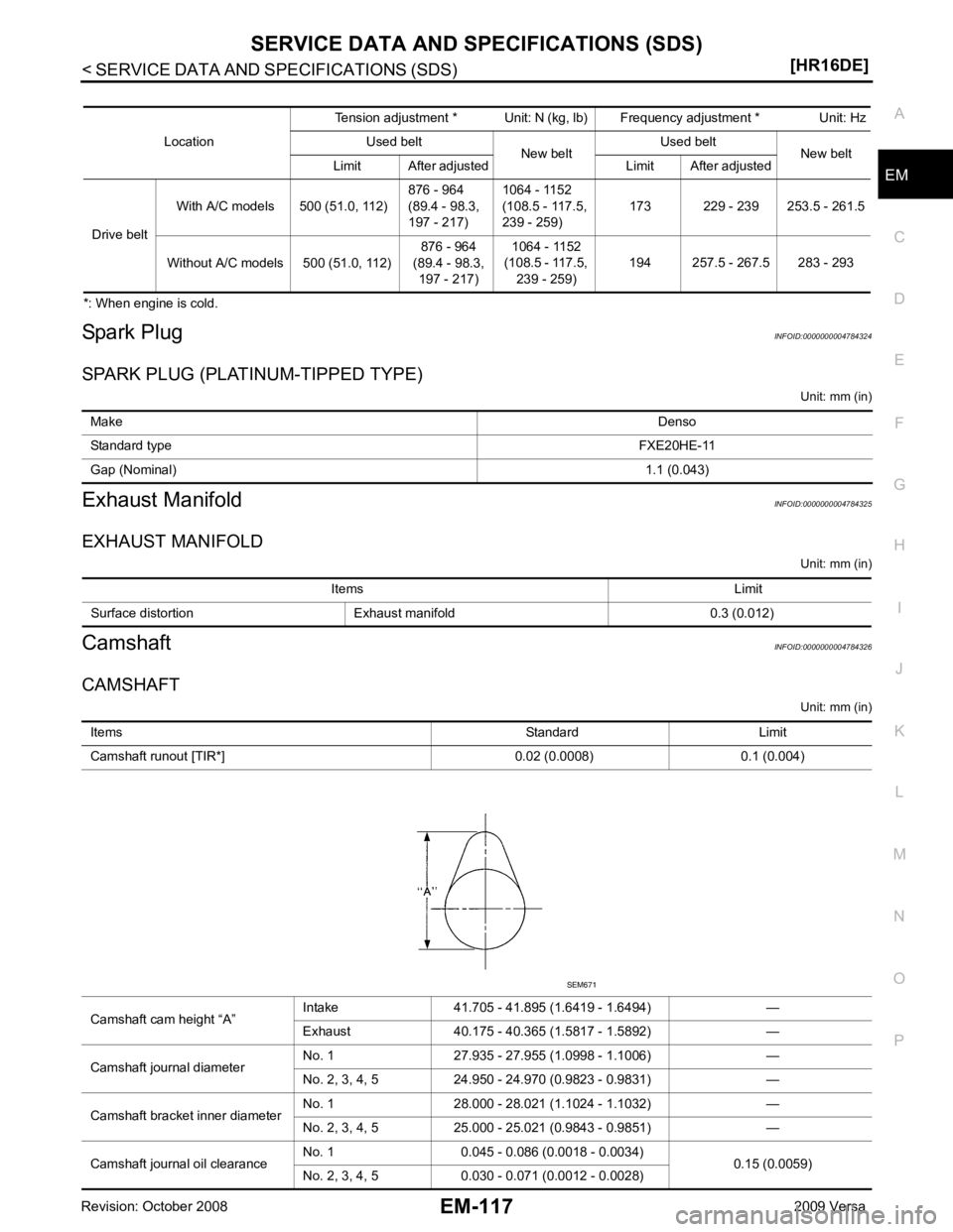
Camshaft runout [TIR*] 0.02 (0.0008) 0.1 (0.004)
Camshaft cam height “A” Intake 41.705 - 41.895 (1.6419 - 1.6494) —
Exhaust 40.175 - 40.365 (1.5817 - 1.5892) —
Camshaft journal diameter No. 1 27.935 - 27.955 (1.0998 - 1.1006) —
No. 2, 3, 4, 5 24.950 - 24.970 (0.9823 - 0.9831) —
Camshaft bracket inner diameter No. 1 28.000 - 28.021 (1.1024 - 1.1032) —
No. 2, 3, 4, 5 25.000 - 25.021 (0.9843 - 0.9851) —
Camshaft journal oil clearance No. 1 0.045 - 0.086 (0.0018 - 0.0034)
0.15 (0.0059)
No. 2, 3, 4, 5 0.030 - 0.071 (0.0012 - 0.0028)
Page 3082 of 4331
EM
NP
O
Use the Chart Below to Help You
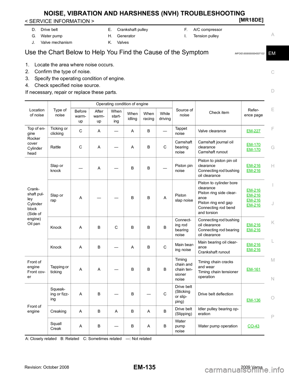
Find the Cause of the Symptom INFOID:0000000004307122
1. Locate the area where noise occurs.
2. Confirm the type of noise.
3. Specify the operating condition of engine.
4. Check specified noise source.
If necessary, repair or replace these parts.
A: Closely related B: Related C: Sometimes related —: Not related D. Drive belt E. Crankshaft pulley F. A/C compressor
G. Water pump H. Generator I. Tension pulley
J. Valve mechanism K. Valves
Location of noise Type of
noise Operating condition of engine
Source of noise Check item
Refer-
ence page
Before
warm-
up After
warm-
up When
start-
ing When
idling When
racing While
driving
Top of en-
gine
Rocker
cover
Cylinder
head Ticking or
clicking C A — A B —
Tappet
noise Valve clearance
EM-227 Rattle C A — A B C
Camshaft
bearing
noise Camshaft journal oil
clearance
Camshaft runout EM-170 EM-170
Crank-
shaft pul-
ley
Cylinder
block
(Side of
engine)
Oil pan Slap or
knock — A — B B —
Piston pin
noise Piston to piston pin oil
clearance
Connecting rod bushing
oil clearance EM-216 EM-216
Slap or
rap A — — B B A
Piston
slap noise Piston to cylinder bore
clearance
Piston ring side clear-
ance
Piston ring end gap
Connecting rod bend
and torsion EM-216 EM-216
EM-216
EM-216
Knock A B C B B B
Connect-
ing rod
bearing
noise Connecting rod bushing
oil clearance
Connecting rod bearing
oil clearance EM-216 EM-216
Knock A B — A B C
Main bear-
ing noise Main bearing oil clear-
ance
Crankshaft runout EM-216 EM-216
Front of
engine
Front cov-
er Tapping or
ticking A A — B B B Timing
chain and
chain ten-
sioner
noise Timing chain cracks
and wear
Timing chain tensioner
operation EM-161Front of
engine Squeak-
ing or fizz-
ing A B — B — C Drive belt
(Sticking
or slip-
ping) Drive belt deflection
EM-136 Creaking A B A B A B
Drive belt
(Slipping) Idler pulley bearing op-
eration
Squall
Creak A B — B A B Water
pump
noise Water pump operation
CO-43
Page 3096 of 4331
EM
NP
O
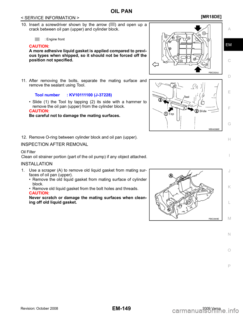
10. Insert a screwdriver shown by the arrow ( ) and open up a
crack between oil pan (upper) and cylinder block.
CAUTION:
A more adhesive liquid gasket is applied compared to previ-
ous types when shipped, so it should not be forced off the
position not specified.
11. After removing the bolts, separate the mating surface and remove the sealant using Tool.
• Slide (1) the Tool by tapping (2) its side with a hammer to remove the oil pan (upper) from the cylinder block.
CAUTION:
Be careful not to damage the mating surfaces.
12. Remove O-ring between cylinder block and oil pan (upper).
INSPECTION AFTER REMOVAL
Oil Filter Clean oil strainer portion (part of the oil pump) if any object attached.
INSTALLATION 1. Use a scraper (A) to remove old liquid gasket from mating sur- faces of oil pan (upper).
• Remove the old liquid gasket from mating surface of cylinder
block.
• Remove old liquid gasket from the bolt holes and threads.
CAUTION:
Never scratch or damage the mating surfaces when clean-
ing off old liquid gasket. : Engine front
Page 3109 of 4331
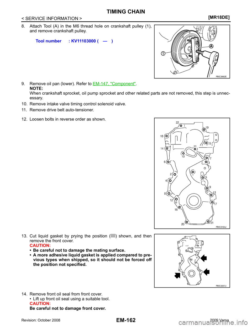
Component " .
NOTE:
When crankshaft sprocket, oil pump sprocket and other related parts are not removed, this step is unnec-
essary.
10. Remove intake valve timing control solenoid valve.
11. Remove drive belt auto-tensioner.
12. Loosen bolts in reverse order as shown.
13. Cut liquid gasket by prying the position ( ) shown, and then remove the front cover.
CAUTION:
• Be careful not to damage the mating surface.
• A more adhesive liquid gasket is applied compared to pre- vious types when shipped, so it should not be forced off
the position not specified.
14. Remove front oil seal from front cover. • Lift up front oil seal using a suitable tool.
CAUTION:
Be careful not to damage front cover. Tool number : KV11103000 ( — )
PBIC3164J
PBIC3357J
Page 3124 of 4331
![NISSAN LATIO 2009 Service Repair Manual CAMSHAFT
EM-177
< SERVICE INFORMATION >
[MR18DE] C
D E
F
G H
I
J
K L
M A EM
NP
O
10. Install camshaft sprocket (EXH) (2).
NOTE:
Secure the hexagonal part (A) of camshaft (EXH) using wrench
to tighten NISSAN LATIO 2009 Service Repair Manual CAMSHAFT
EM-177
< SERVICE INFORMATION >
[MR18DE] C
D E
F
G H
I
J
K L
M A EM
NP
O
10. Install camshaft sprocket (EXH) (2).
NOTE:
Secure the hexagonal part (A) of camshaft (EXH) using wrench
to tighten](/manual-img/5/57359/w960_57359-3123.png)
CAMSHAFT
EM-177
< SERVICE INFORMATION >
[MR18DE] C
D E
F
G H
I
J
K L
M A EM
NP
O
10. Install camshaft sprocket (EXH) (2).
NOTE:
Secure the hexagonal part (A) of camshaft (EXH) using wrench
to tighten bolt.
11. Install timing chain and related parts. Refer to EM-160 .
12. Inspect and adjust valve clearance. Refer to EM-178, " Valve Clearance " .
13. Installation of the remaining components is in the reverse order of removal.
INSPECTION AFTER INSTALLATION The following are procedures for chec king fluids leak, lubricates leak.
• Before starting engine, check oil/fluid levels incl uding engine coolant and engine oil. If less than required
quantity, fill to the specified level. Refer to GI-42, " Recommended Chemical Product and Sealant " .
• Use procedure below to check for fuel leakage.
- Turn ignition switch “ON” (with engine stopped). With fuel pressure applied to fuel piping, check for fuel leak-
age at connection points.
- Start engine. With engine speed increased, check again for fuel leakage at connection points.
• Run engine to check for unusual noise and vibration. NOTE:
If hydraulic pressure inside timing chain tensioner drops after removal/installation, slack in the guide may
generate a pounding noise during and just after engine start. However, this is normal. Noise will stop after
hydraulic pressure rises.
• Warm up engine thoroughly to make sure there is no leak age of fuel, or any oil/fluids including engine oil and
engine coolant.
• Bleed air from lines and hoses of applicable lines, such as in cooling system.
• After cooling down engine, again check oil/fluid levels including engine oil and engine coolant. Refill to the
specified level, if necessary.
Summary of the inspection items:
* Transmission/transaxle/CVT fluid, power steering fluid, brake fluid, etc.
Inspection of Camshaft Sprocket (INT) Oil Groove
CAUTION:
• Perform this inspection only when DTC P0011 is detected in self-diagnostic results of CONSULT-III
and it is directed according to inspect ion procedure of EC section. Refer to EC-638, " Diagnosis Pro-
cedure " (Type 1) or
EC-1153, " Diagnosis Procedure " (Type 2).
• Check when engine is cold so as to pr event burns from the splashing engine oil.
1. Check engine oil level. Refer to LU-16, " Inspection " .
2. Perform the following procedure so as to prevent the engine from being unintentionally started while checking.
a. Remove intake manifold. Refer to EM-141, " Component " .
b. Disconnect ignition coil and in jector harness connectors.
3. Remove intake valve timing control solenoid valve. Refer to EM-160, " Component " .
1 : Camshaft sprocket (INT)
Camshaft sprocket
bolt (EXH) : 88.2 N·m (9.0 kg-m, 65 ft-lb) PBIC3454J
Item Before starting engine Engine running After engine stopped
Engine coolant Level Leakage Level
Engine oil Level Leakage Level
Other oils and fluid* Level Leakage Level
Fuel Leakage Leakage Leakage
Exhaust gases — Leakage —
Page 3132 of 4331
EM
NP
O
CYLINDER HEAD
On-Vehicle Service INFOID:0000000004307150
CHECKING COMPRESSION PRESSURE 1. Warm up engine thoroughly. Then, stop it.
2. Release fuel pressure. Refer to EC-574, " Fuel Pressure Check " (Type 1) or
EC-1086, " Fuel Pressure
Check " (Type 2).
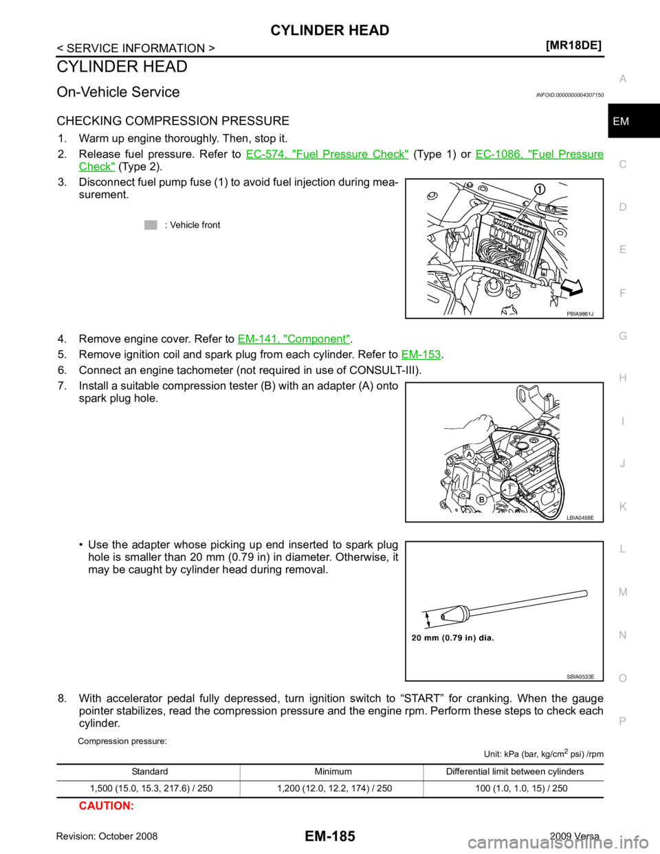
3. Disconnect fuel pump fuse (1) to avoid fuel injection during mea- surement.
4. Remove engine cover. Refer to EM-141, " Component " .
5. Remove ignition coil and spark plug from each cylinder. Refer to EM-153 .
6. Connect an engine tachometer (not required in use of CONSULT-III).
7. Install a suitable compression tester (B) with an adapter (A) onto spark plug hole.
• Use the adapter whose picking up end inserted to spark plug hole is smaller than 20 mm (0.79 in) in diameter. Otherwise, it
may be caught by cylinder head during removal.
8. With accelerator pedal fully depressed, turn ignition switch to “START” for cranking. When the gauge pointer stabilizes, read the compression pressure and the engine rpm. Perform these steps to check each
cylinder.
Compression pressure: Unit: kPa (bar, kg/cm2
psi) /rpm
CAUTION: : Vehicle front
LBIA0459E
SBIA0533E