2009 NISSAN LATIO oil type
[x] Cancel search: oil typePage 3753 of 4331
![NISSAN LATIO 2009 Service Repair Manual (HR)
MA-26 (MR)
Air cleaner filter NOTE
(2) [R]
MA-20 (HR)
MA-29 (MR)
EVAP vapor lines I*MA-25 (HR)
MA-36 (MR)
Fuel lines I*MA-29 Fuel filter
NOTE
(3) —
Engine coolant NOTE
(4) R*
MA-17 (H NISSAN LATIO 2009 Service Repair Manual (HR)
MA-26 (MR)
Air cleaner filter NOTE
(2) [R]
MA-20 (HR)
MA-29 (MR)
EVAP vapor lines I*MA-25 (HR)
MA-36 (MR)
Fuel lines I*MA-29 Fuel filter
NOTE
(3) —
Engine coolant NOTE
(4) R*
MA-17 (H](/manual-img/5/57359/w960_57359-3752.png)
(HR)
MA-26 (MR)
Air cleaner filter NOTE
(2) [R]
MA-20 (HR)
MA-29 (MR)
EVAP vapor lines I*MA-25 (HR)
MA-36 (MR)
Fuel lines I*MA-29 Fuel filter
NOTE
(3) —
Engine coolant NOTE
(4) R*
MA-17 (HR)
MA-26 (MR)
Engine oil R R R R R R R R MA-20 (HR)
MA-30 (MR)
Engine oil filter (Use
genuine oil filter or
equivalent) R R R R R R R R
MA-23 (HR)
MA-33 (MR)
Spark plugs (Iridium-
tipped type) Replace every 105,000 miles (169,000 km) MA-24 (HR)
MA-34 (MR)
Intake and exhaust
valve clearance* NOTE
(5) EM-119, " Cylinder Head "
(HR)
EM-227, " Standard and
Limit " (MR)
Brake pads, rotors,
drums & linings I I I I MA-47 MA-47
Manual transaxle oil or
automatic transaxle
fluid NOTE (1) I I MA-43
(RS5F91R) MA-44
(RS6F94R)
MA-44 (A/T)
Page 3755 of 4331
![NISSAN LATIO 2009 Service Repair Manual (HR)
MA-26 (MR)
Air cleaner filter [R] [R] MA-20 (HR)
MA-29 (MR)
EVAP vapor lines I* I* MA-25 (HR)
MA-36 (MR)
Fuel lines I* I* MA-29Fuel filter NOTE (2)
—
Engine coolant NOTE (3) R*MA-17 (HR) NISSAN LATIO 2009 Service Repair Manual (HR)
MA-26 (MR)
Air cleaner filter [R] [R] MA-20 (HR)
MA-29 (MR)
EVAP vapor lines I* I* MA-25 (HR)
MA-36 (MR)
Fuel lines I* I* MA-29Fuel filter NOTE (2)
—
Engine coolant NOTE (3) R*MA-17 (HR)](/manual-img/5/57359/w960_57359-3754.png)
(HR)
MA-26 (MR)
Air cleaner filter [R] [R] MA-20 (HR)
MA-29 (MR)
EVAP vapor lines I* I* MA-25 (HR)
MA-36 (MR)
Fuel lines I* I* MA-29Fuel filter NOTE (2)
—
Engine coolant NOTE (3) R*MA-17 (HR)
MA-26 (MR)
Engine oil R R R R R R R R MA-20 (HR)
MA-30 (MR)
Engine oil filter (Use genuine
oil filter or equivalent.) R R R R R R R R MA-23 (HR)
MA-33 (MR)
Spark plugs (Iridium-tipped
type) Replace every 105,000 miles (169,000 km) MA-24 (HR)
MA-34 (MR)
Intake and exhaust valve
clearance* NOTE (4) EM-119, " Cyl-
inder Head "
(HR)
EM-227, " Stan-
dard and Limit "
(MR) Brake pads, rotors, drums & lin-
ings I I I IMA-47 MA-47
Manual transaxle oil or automatic
transaxle fluid I I I IMA-43
(RS5F91R) MA-44
(RS6F94R)
MA-44 (A/T)
CVT fluid NOTE (1) I I I I MA-38
(RE0F08A) MA-39
(RE0F08B)
Page 3758 of 4331
MA
N
O P
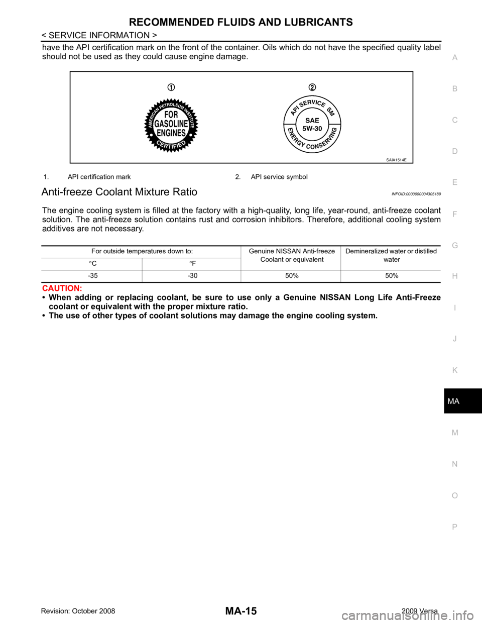
have the API certification mark on the front of the c
ontainer. Oils which do not have the specified quality label
should not be used as they could cause engine damage.
Anti-freeze Coolant Mixture Ratio INFOID:0000000004305189
The engine cooling system is filled at the factory wit h a high-quality, long life, year-round, anti-freeze coolant
solution. The anti-freeze solution contains rust and corr osion inhibitors. Therefore, additional cooling system
additives are not necessary.
CAUTION:
• When adding or replacing coolant, be sure to use only a Genuine NISSAN Long Life Anti-Freeze
coolant or equivalent with the proper mixture ratio.
• The use of other types of coolant soluti ons may damage the engine cooling system.
Page 3837 of 4331
MT
N
O P
SERVICE DATA AND SPECIFICATIONS (SDS)
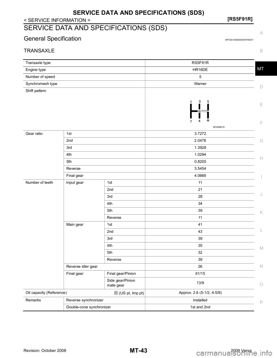
General Specification INFOID:0000000004784251
TRANSAXLE Transaxle type RS5F91R
Engine type HR16DE
Number of speed 5
Synchromesh type Warner
Shift pattern
Gear ratio 1st 3.7272
2nd 2.0476
3rd 1.3928
4th 1.0294
5th 0.8205
Reverse 3.5454
Final gear 4.0666
Number of teeth Input gear 1st 11 2nd 21
3rd 28
4th 34
5th 39
Reverse 11
Main gear 1st 41 2nd 43
3rd 39
4th 35
5th 32
Reverse 39
Reverse idler gear 26
Final gear Final gear/Pinion 61/15 Side gear/Pinion
mate gear 13/9
Oil capacity (Reference) (US pt, Imp pt)Approx. 2.6 (5-1/2, 4-5/8)
Remarks Reverse synchronizer Installed Double-cone synchronizer 1st and 2nd
Page 3838 of 4331
![NISSAN LATIO 2009 Service Repair Manual MT-44< SERVICE INFORMATION >
[RS6F94R]
PRECAUTIONS
SERVICE INFORMATION
PRECAUTIONS
Precaution for Supplemental Restraint Syst em (SRS) "AIR BAG" and "SEAT BELT
PRE-TENSIONER" INFOID:0000000004305264
NISSAN LATIO 2009 Service Repair Manual MT-44< SERVICE INFORMATION >
[RS6F94R]
PRECAUTIONS
SERVICE INFORMATION
PRECAUTIONS
Precaution for Supplemental Restraint Syst em (SRS) "AIR BAG" and "SEAT BELT
PRE-TENSIONER" INFOID:0000000004305264](/manual-img/5/57359/w960_57359-3837.png)
MT-44< SERVICE INFORMATION >
[RS6F94R]
PRECAUTIONS
SERVICE INFORMATION
PRECAUTIONS
Precaution for Supplemental Restraint Syst em (SRS) "AIR BAG" and "SEAT BELT
PRE-TENSIONER" INFOID:0000000004305264
The Supplemental Restraint System such as “A IR BAG” and “SEAT BELT PRE-TENSIONER”, used along
with a front seat belt, helps to reduce the risk or severi ty of injury to the driver and front passenger for certain
types of collision. This system includes seat belt switch inputs and dual stage front air bag modules. The SRS
system uses the seat belt switches to determine the front air bag deployment, and may only deploy one front
air bag, depending on the severity of a collision and w hether the front occupants are belted or unbelted.
Information necessary to service the system safely is included in the SRS and SB section of this Service Man-
ual.
WARNING:
• To avoid rendering the SRS inopera tive, which could increase the risk of personal injury or death in
the event of a collision which would result in air bag inflation, all maintenance must be performed by
an authorized NISS AN/INFINITI dealer.
• Improper maintenance, including in correct removal and installation of the SRS, can lead to personal
injury caused by unintent ional activation of the system. For re moval of Spiral Cable and Air Bag
Module, see the SRS section.
• Do not use electrical test equipmen t on any circuit related to the SRS unless instructed to in this
Service Manual. SRS wiring harn esses can be identified by yellow and/or orange harnesses or har-
ness connectors.
Precaution for Procedure without Cowl Top Cover INFOID:0000000004305265
When performing the procedure after removing cowl top cover, cover
the lower end of windshield with urethane, etc.
Precaution INFOID:0000000004305266
• If transaxle assembly is removed from the vehi cle, always replace CSC (Concentric Slave Cylinder).
Installed CSC returns to the original position when removing transaxle assembly. Dust on clutch disc sliding
parts may damage CSC seal, and may cause clutch fluid leakage.
• Do not reuse transaxle oil.
• Drain, fill and check transaxle oil with the vehicle on level surface.
• During removal or installation, keep inside of transaxle clear of dust or dirt.
• Check for the correct installation orientation prior to removal or disassembly. If matching marks are required,
be certain they do not interfere with the f unction of the parts they are applied to.
• In principle, tighten bolts or nuts gradually in several steps working diagonally from inside to outside. If tight-
ening sequence is specified, follow it.
• Be careful not to damage the sliding surfaces and mating surfaces of parts. PIIB3706J
Page 3885 of 4331
MT
N
O P
SERVICE DATA AND SPECIFICATIONS (SDS)
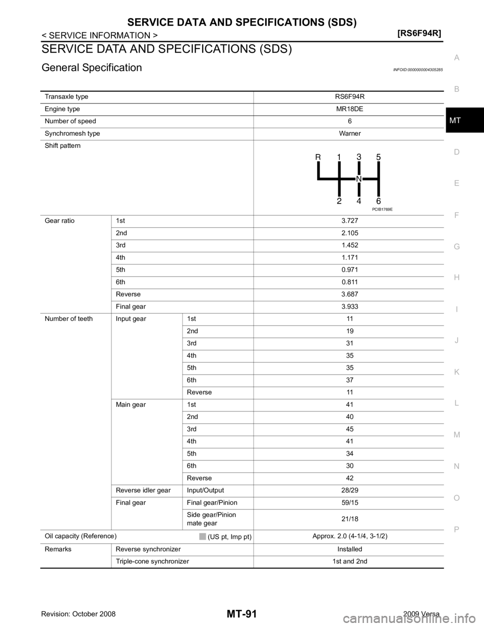
General Specification INFOID:0000000004305285
Transaxle type RS6F94R
Engine type MR18DE
Number of speed 6
Synchromesh type Warner
Shift pattern
Gear ratio 1st 3.727
2nd 2.105
3rd 1.452
4th 1.171
5th 0.971
6th 0.811
Reverse 3.687
Final gear 3.933
Number of teeth Input gear 1st 11 2nd 19
3rd 31
4th 35
5th 35
6th 37
Reverse 11
Main gear 1st 41 2nd 40
3rd 45
4th 41
5th 34
6th 30
Reverse 42
Reverse idler gear Input/Output 28/29
Final gear Final gear/Pinion 59/15 Side gear/Pinion
mate gear 21/18
Oil capacity (Reference) (US pt, Imp pt)Approx. 2.0 (4-1/4, 3-1/2)
Remarks Reverse synchronizer Installed Triple-cone synchronizer 1st and 2nd
Page 3890 of 4331
MTC
N
O P
been shown to be combustible at
elevated pressures. These mixtures, if ignited, may cause injury or
property damage. Additional health and safety info rmation may be obtained from refrigerant manu-
facturers.
Oil Precaution INFOID:0000000004307045
• Use only specified oil for the HFC-134a (R-134a) A/C system and HFC-134a (R-134a) components. If oil
other than that specified is used, comp ressor malfunction is likely to occur.
• The specified HFC-134a (R-134a) oil rapidly absorbs mo isture from the atmosphere. The following handling
precautions must be observed:
- When removing refrigerant components from a vehicle, immediately cap (seal) the component to minimize the entry of moisture from the atmosphere.
- When installing refrigerant components to a vehicle, do not remove the caps (unseal) until just before con- necting the components. Connect all refrigerant loop components as quickly as possible to minimize the
entry of moisture into system.
- Only use the specified oil from a sealed container. Imm ediately reseal containers of oil. Without proper seal-
ing, oil will become moisture saturated and should not be used.
• Avoid breathing A/C refrigerant and oil vapor or mist. Exposure may irritate eyes, nose and throat.
Use only approved recovery/recycling equipment to discharge HFC-134a (R-134a) refrigerant. If accidental
system discharge occurs, ventilate work area before re suming service. Additional health and safety informa-
tion may be obtained from refrigerant and oil manufacturers.
• Do not allow A/C oil to come in contact with styrofoam parts. Damage may result.
Precaution for Refrigerant Connection INFOID:0000000004307046
A new type refrigerant connection has been introduced to a ll refrigerant lines except the following location.
• Expansion valve to evaporator
• Refrigerant pressure sensor to condenser
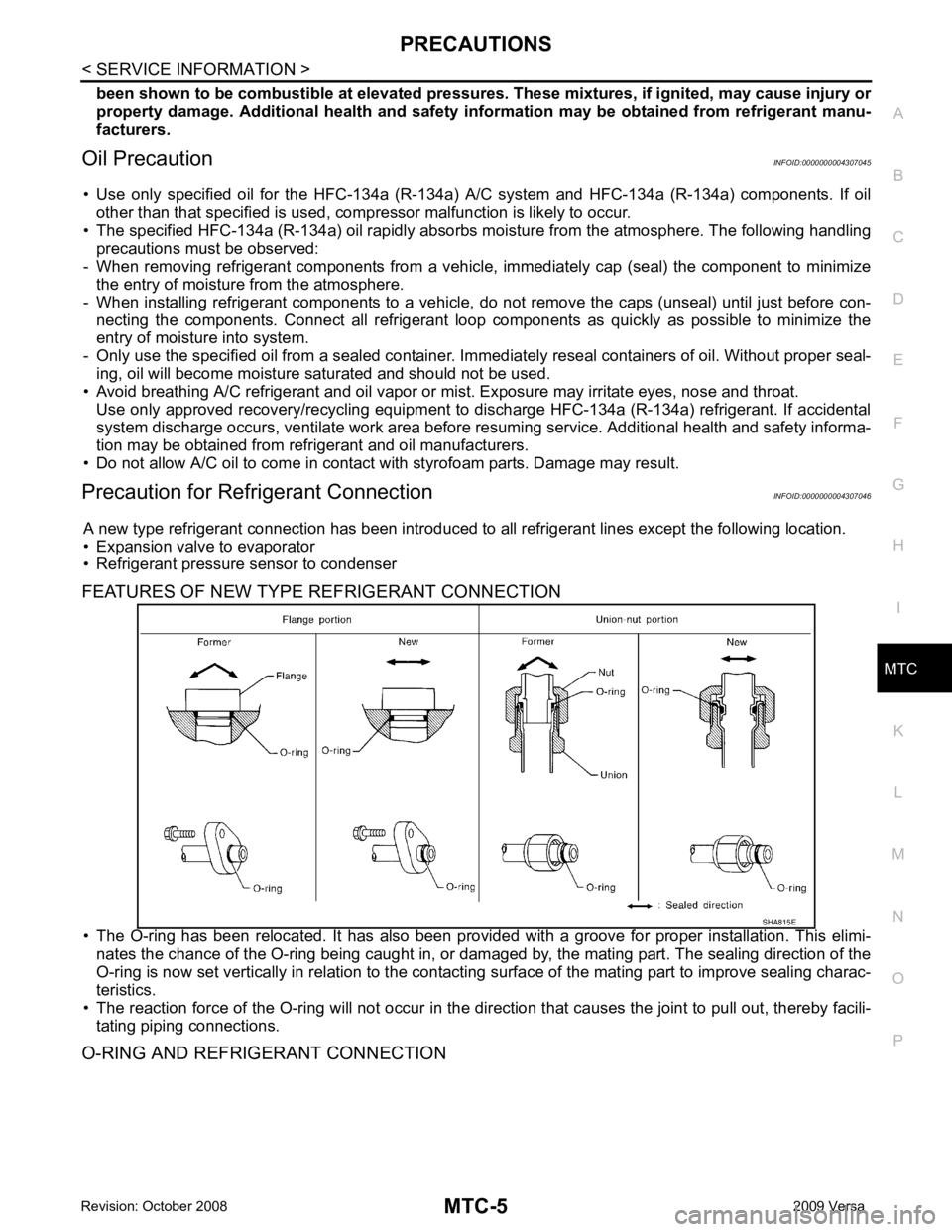
FEATURES OF NEW TYPE REFRIGERANT CONNECTION
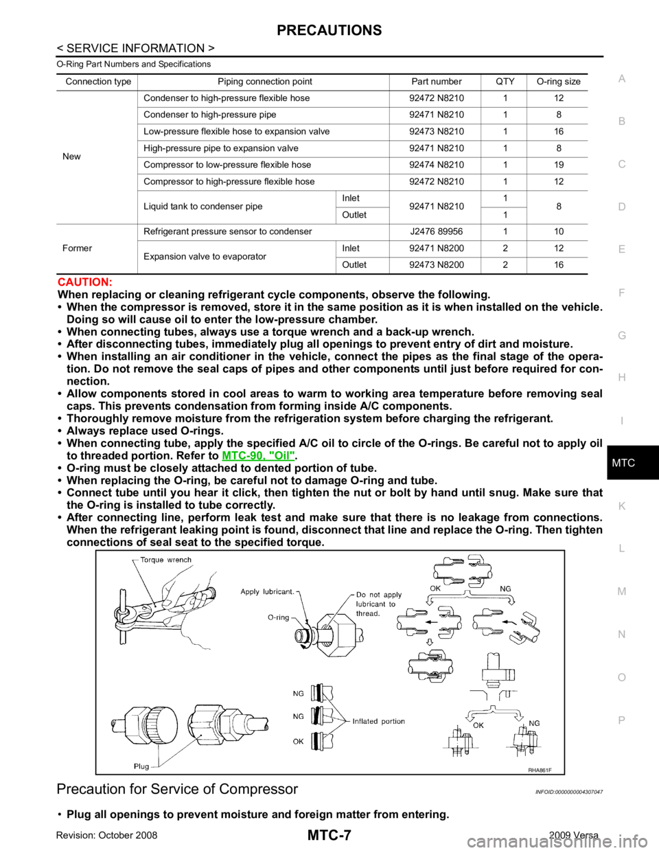
• The O-ring has been relocated. It has also been provided with a groove for proper installation. This elimi- nates the chance of the O-ring being caught in, or damaged by, the mating part. The sealing direction of the
O-ring is now set vertically in relation to the contacti ng surface of the mating part to improve sealing charac-
teristics.
• The reaction force of the O-ring will not occur in the dire ction that causes the joint to pull out, thereby facili-
tating piping connections.
O-RING AND REFRIGERANT CONNECTION
Page 3892 of 4331
MTC
N
O P
O-Ring Part Numbers and Specifications
CAUTION:
When replacing or cleaning refrigerant cycle components, observe the following.
• When the compressor is removed, store it in the sam e position as it is when installed on the vehicle.
Doing so will cause oil to en ter the low-pressure chamber.
• When connecting tubes, always use a to rque wrench and a back-up wrench.
• After disconnecting tubes, immediately plug all op enings to prevent entry of dirt and moisture.
• When installing an air conditione r in the vehicle, connect the pipes as the final stage of the opera-
tion. Do not remove the seal caps of pipes and other components until just before required for con-
nection.
• Allow components stored in cool areas to warm to working area temperature before removing seal
caps. This prevents condensation from forming inside A/C components.
• Thoroughly remove moisture from the refriger ation system before charging the refrigerant.
• Always replace used O-rings.
• When connecting tube, apply the speci fied A/C oil to circle of the O-rings. Be careful not to apply oil
to threaded portion. Refer to MTC-90, " Oil " .
• O-ring must be closely attached to dented portion of tube.
• When replacing the O-ring, be careful not to damage O-ring and tube.
• Connect tube until you hear it cl ick, then tighten the nut or bolt by hand until snug. Make sure that
the O-ring is installed to tube correctly.
• After connecting line, perform leak test and make sure that there is no leakage from connections.
When the refrigerant leaking point is found, disconnect that line and replace the O-ring. Then tighten
connections of seal seat to the specified torque.
Precaution for Service of Compressor INFOID:0000000004307047
• Plug all openings to prevent moisture and foreign matter from entering.
Connection type Piping connection point Part number QTY O-ring size
New Condenser to high-pressure flexible hose 92472 N8210 1 12
Condenser to high-pressure pipe 92471 N8210 1 8
Low-pressure flexible hose to expansion valve 92473 N8210 1 16
High-pressure pipe to expansion valve 92471 N8210 1 8
Compressor to low-pressure flexible hose 92474 N8210 1 19
Compressor to high-pressure flexible hose 92472 N8210 1 12
Liquid tank to condenser pipe Inlet
92471 N8210 1
8
Outlet 1
Former Refrigerant pressure sensor to condenser J2476 89956 1 10
Expansion valve to evaporator Inlet 92471 N8200 2 12
Outlet 92473 N8200 2 16