2008 NISSAN TEANA engine
[x] Cancel search: enginePage 2528 of 5121
SERVICE INFORMATION FOR ELECTRICAL INCIDENT
GI-35
< BASIC INSPECTION >
C
D
E
F
G
H
I
J
K
L
MB
GI
N
O
P
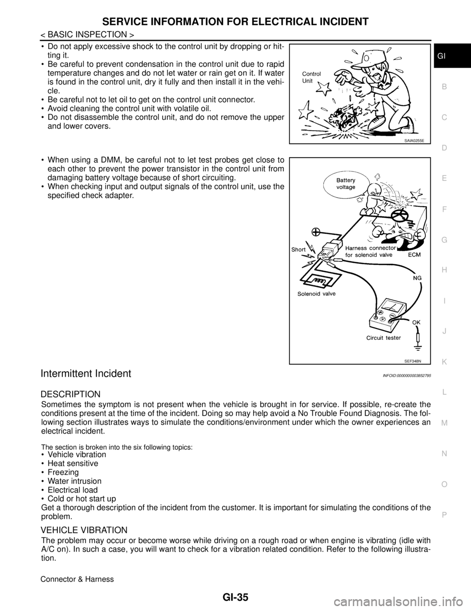
Do not apply excessive shock to the control unit by dropping or hit-
ting it.
Be careful to prevent condensation in the control unit due to rapid
temperature changes and do not let water or rain get on it. If water
is found in the control unit, dry it fully and then install it in the vehi-
cle.
Be careful not to let oil to get on the control unit connector.
Avoid cleaning the control unit with volatile oil.
Do not disassemble the control unit, and do not remove the upper
and lower covers.
When using a DMM, be careful not to let test probes get close to
each other to prevent the power transistor in the control unit from
damaging battery voltage because of short circuiting.
When checking input and output signals of the control unit, use the
specified check adapter.
Intermittent IncidentINFOID:0000000003852795
DESCRIPTION
Sometimes the symptom is not present when the vehicle is brought in for service. If possible, re-create the
conditions present at the time of the incident. Doing so may help avoid a No Trouble Found Diagnosis. The fol-
lowing section illustrates ways to simulate the conditions/environment under which the owner experiences an
electrical incident.
The section is broken into the six following topics: Vehicle vibration
Heat sensitive
Freezing
Water intrusion
Electrical load
Cold or hot start up
Get a thorough description of the incident from the customer. It is important for simulating the conditions of the
problem.
VEHICLE VIBRATION
The problem may occur or become worse while driving on a rough road or when engine is vibrating (idle with
A/C on). In such a case, you will want to check for a vibration related condition. Refer to the following illustra-
tion.
Connector & Harness
SAIA0255E
SEF348N
Page 2529 of 5121
GI-36
< BASIC INSPECTION >
SERVICE INFORMATION FOR ELECTRICAL INCIDENT
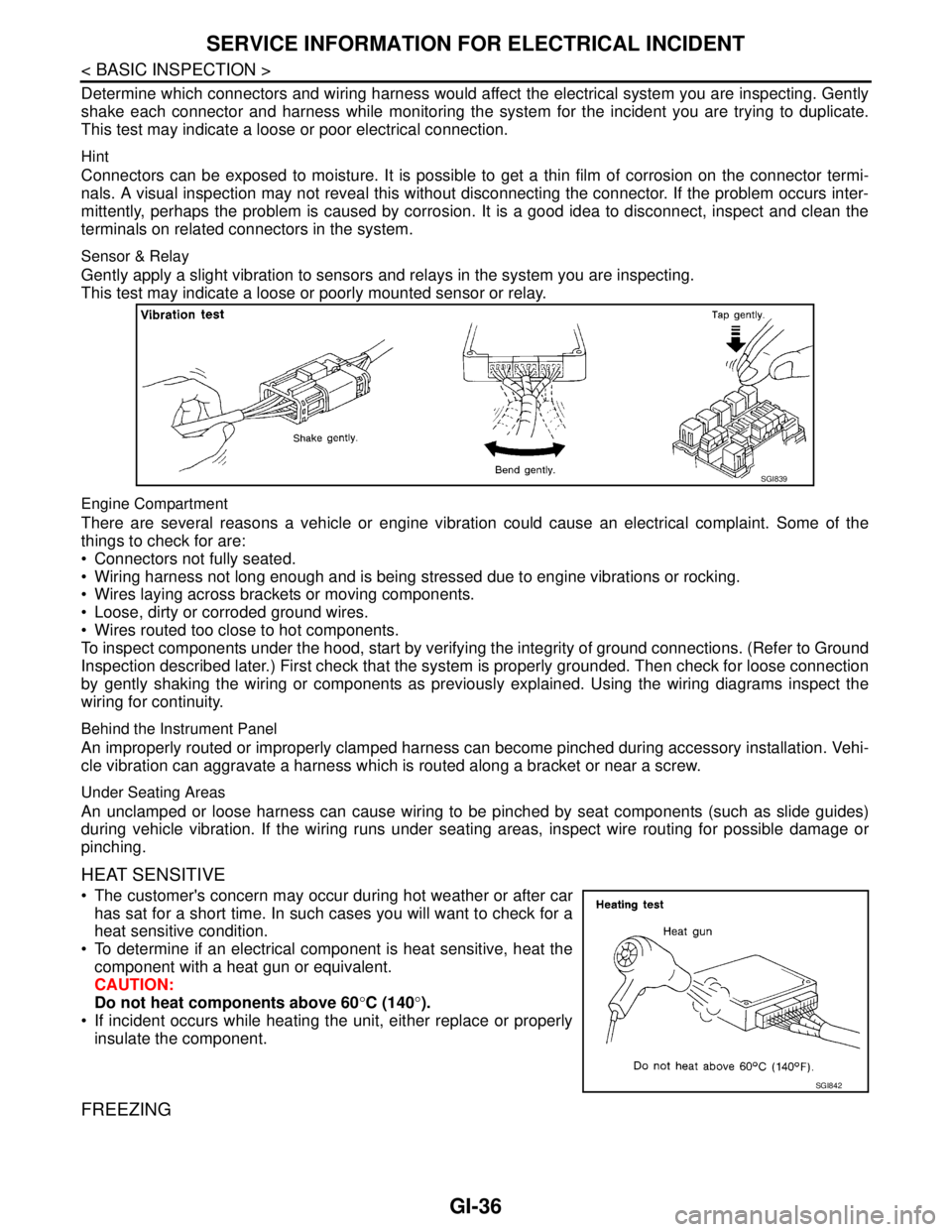
Determine which connectors and wiring harness would affect the electrical system you are inspecting. Gently
shake each connector and harness while monitoring the system for the incident you are trying to duplicate.
This test may indicate a loose or poor electrical connection.
Hint
Connectors can be exposed to moisture. It is possible to get a thin film of corrosion on the connector termi-
nals. A visual inspection may not reveal this without disconnecting the connector. If the problem occurs inter-
mittently, perhaps the problem is caused by corrosion. It is a good idea to disconnect, inspect and clean the
terminals on related connectors in the system.
Sensor & Relay
Gently apply a slight vibration to sensors and relays in the system you are inspecting.
This test may indicate a loose or poorly mounted sensor or relay.
Engine Compartment
There are several reasons a vehicle or engine vibration could cause an electrical complaint. Some of the
things to check for are:
Connectors not fully seated.
Wiring harness not long enough and is being stressed due to engine vibrations or rocking.
Wires laying across brackets or moving components.
Loose, dirty or corroded ground wires.
Wires routed too close to hot components.
To inspect components under the hood, start by verifying the integrity of ground connections. (Refer to Ground
Inspection described later.) First check that the system is properly grounded. Then check for loose connection
by gently shaking the wiring or components as previously explained. Using the wiring diagrams inspect the
wiring for continuity.
Behind the Instrument Panel
An improperly routed or improperly clamped harness can become pinched during accessory installation. Vehi-
cle vibration can aggravate a harness which is routed along a bracket or near a screw.
Under Seating Areas
An unclamped or loose harness can cause wiring to be pinched by seat components (such as slide guides)
during vehicle vibration. If the wiring runs under seating areas, inspect wire routing for possible damage or
pinching.
HEAT SENSITIVE
The customer's concern may occur during hot weather or after car
has sat for a short time. In such cases you will want to check for a
heat sensitive condition.
To determine if an electrical component is heat sensitive, heat the
component with a heat gun or equivalent.
CAUTION:
Do not heat components above 60°C (140°).
If incident occurs while heating the unit, either replace or properly
insulate the component.
FREEZING
SGI839
SGI842
Page 2536 of 5121
CONSULT-III/GST CHECKING SYSTEM
GI-43
< BASIC INSPECTION >
C
D
E
F
G
H
I
J
K
L
MB
GI
N
O
PCONSULT-III/GST CHECKING SYSTEM
DescriptionINFOID:0000000003852797
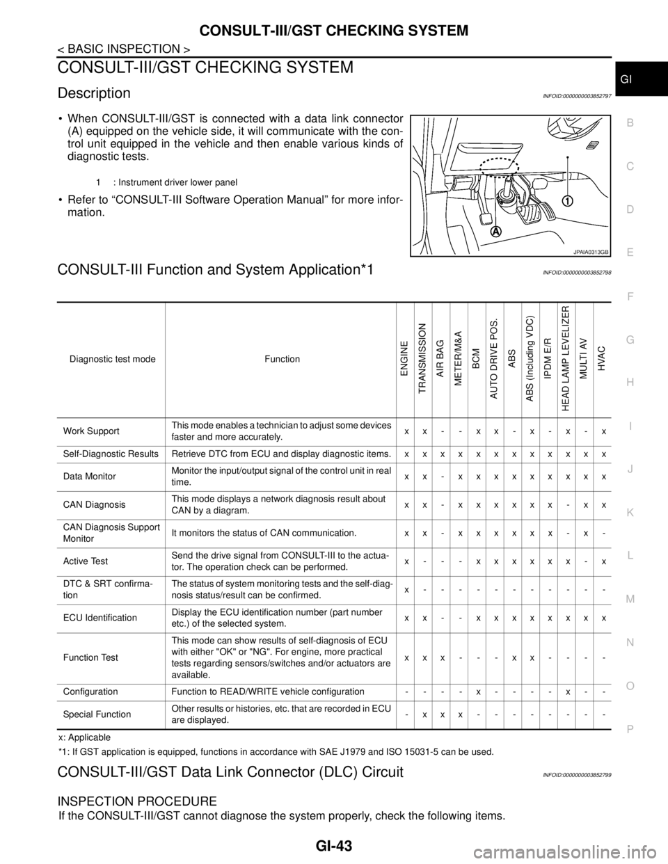
When CONSULT-III/GST is connected with a data link connector
(A) equipped on the vehicle side, it will communicate with the con-
trol unit equipped in the vehicle and then enable various kinds of
diagnostic tests.
Refer to “CONSULT-III Software Operation Manual” for more infor-
mation.
CONSULT-III Function and System Application*1INFOID:0000000003852798
x: Applicable
*1: If GST application is equipped, functions in accordance with SAE J1979 and ISO 15031-5 can be used.
CONSULT-III/GST Data Link Connector (DLC) CircuitINFOID:0000000003852799
INSPECTION PROCEDURE
If the CONSULT-III/GST cannot diagnose the system properly, check the following items.
1 : Instrument driver lower panel
JPAIA0313GB
Diagnostic test mode Function
ENGINE
TRANSMISSION
AIR BAG
METER/M&A
BCM
AUTO DRIVE POS.
ABS
ABS (Including VDC)
IPDM E/R
HEAD LAMP LEVELIZER
MULTI AV
HVAC
Work SupportThis mode enables a technician to adjust some devices
faster and more accurately.xx- -xx-x-x-x
Self-Diagnostic Results Retrieve DTC from ECU and display diagnostic items. x x x x x x x x x x x x
Data MonitorMonitor the input/output signal of the control unit in real
time.xx - xxxxxxxxx
CAN DiagnosisThis mode displays a network diagnosis result about
CAN by a diagram.xx - xxxxxx - xx
CAN Diagnosis Support
MonitorIt monitors the status of CAN communication. x x - x x x x x x - x -
Active TestSend the drive signal from CONSULT-III to the actua-
tor. The operation check can be performed.x - - - xxxxxx - x
DTC & SRT confirma-
tionThe status of system monitoring tests and the self-diag-
nosis status/result can be confirmed.x-----------
ECU IdentificationDisplay the ECU identification number (part number
etc.) of the selected system.xx - - xxxxxxxx
Function TestThis mode can show results of self-diagnosis of ECU
with either "OK" or "NG". For engine, more practical
tests regarding sensors/switches and/or actuators are
available.xxx---xx----
Configuration Function to READ/WRITE vehicle configuration - - - - x - - - - x - -
Special FunctionOther results or histories, etc. that are recorded in ECU
are displayed.-xxx--------
Page 2543 of 5121

GI-50
< BASIC INSPECTION >
INSPECTION AND ADJUSTMENT
*: Not equippedPower window
controlPower window control systemPWC-5, "
ADDITIONAL SERVICE WHEN
REMOVING BATTERY NEGATIVE TERMI-
NAL : Description"
Sunroof system Sunroof system* —
Sunshade system Sunshade system* —
Rear view monitorRear view monitor
possible route line
center position ad-
justmentDISPLAY AND AUDIO SYSTEMAV- 4 7 , "
ADDITIONAL SERVICE WHEN
REMOVING BATTERY NEGATIVE TERMI-
NAL : Description"
BOSE AUDIO WITHOUT NAVIGATIONAV- 1 8 7 , "
ADDITIONAL SERVICE WHEN
REMOVING BATTERY NEGATIVE TERMI-
NAL : Description"
BOSE AUDIO WITH NAVIGATIONAV- 4 0 0 , "
ADDITIONAL SERVICE WHEN
REMOVING BATTERY NEGATIVE TERMI-
NAL : Description"
Around view moni-
torPredicted conurse line center position adjustment* —
Automatic back
door systemAutomatic back door system* —
Engine oil level
readEngine oil level read* — SYSTEM ITEM REFERENCE
Page 2546 of 5121
SQUEAK AND RATTLE TROUBLE DIAGNOSES
GW-3
< SYMPTOM DIAGNOSIS >
C
D
E
F
G
H
I
J
L
MA
B
GW
N
O
P
If possible, drive the vehicle with the customer until the noise is duplicated. Note any additional information on
the Diagnostic Worksheet regarding the conditions or location of the noise. This information can be used to
duplicate the same conditions when the repair is reconfirmed.
If the noise can be duplicated easily during the test drive, to help identify the source of the noise, try to dupli-
cate the noise with the vehicle stopped by doing one or all of the following:
1) Close a door.
2) Tap or push/pull around the area where the noise appears to be coming from.
3) Rev the engine.
4) Use a floor jack to recreate vehicle “twist”.
5) At idle, apply engine load (electrical load, half-clutch on M/T model, drive position on A/T model).
6) Raise the vehicle on a hoist and hit a tire with a rubber hammer.
Drive the vehicle and attempt to duplicate the conditions the customer states exist when the noise occurs.
If it is difficult to duplicate the noise, drive the vehicle slowly on an undulating or rough road to stress the
vehicle body.
LOCATE THE NOISE AND IDENTIFY THE ROOT CAUSE
1. Narrow down the noise to a general area. To help pinpoint the source of the noise, use a listening tool
(Engine Ear or mechanics stethoscope).
2. Narrow down the noise to a more specific area and identify the cause of the noise by:
Removing the components in the area that is are suspected to be the cause of the noise.
Do not use too much force when removing clips and fasteners, otherwise clips and fastener can be broken
or lost during the repair, resulting in the creation of new noise.
Tapping or pushing/pulling the component that is are suspected to be the cause of the noise.
Do not tap or push/pull the component with excessive force, otherwise the noise will be eliminated only tem-
porarily.
Feeling for a vibration by hand by touching the component(s) that is are suspected to be the cause of the
noise.
Placing a piece of paper between components that is are suspected to be the cause of the noise.
Looking for loose components and contact marks.
Refer to GW-4, "
Inspection Procedure".
REPAIR THE CAUSE
If the cause is a loose component, tighten the component securely.
If the cause is insufficient clearance between components:
- Separate components by repositioning or loosening and retightening the component, if possible.
- Insulate components with a suitable insulator such as urethane pads, foam blocks, felt cloth tape or ure-
thane tape. These insulators are available through the authorized Nissan Parts Department.
CAUTION:
Never use excessive force as many components are constructed of plastic and may be damaged.
NOTE:
URETHANE PADS
Insulates connectors, harness, etc.
INSULATOR (Foam blocks)
Insulates components from contact. Can be used to fill space behind a panel.
INSULATOR (Light foam block)
FELT CLOTHTAPE
Used to insulate where movement does not occur. Ideal for instrument panel applications.
The following materials, not available through NISSAN Parts Department, can also be used to repair
squeaks and rattles.
UHMW(TEFLON) TAPE
Insulates where slight movement is present. Ideal for instrument panel applications.
SILICONE GREASE
Used in place of UHMW tape that is be visible or does not fit.
Note: Will only last a few months.
SILICONE SPRAY
Used when grease cannot be applied.
DUCT TAPE
Used to eliminate movement.
CONFIRM THE REPAIR
Page 2548 of 5121

SQUEAK AND RATTLE TROUBLE DIAGNOSES
GW-5
< SYMPTOM DIAGNOSIS >
C
D
E
F
G
H
I
J
L
MA
B
GW
N
O
P
Again, pressing on the components to stop the noise while duplicating the conditions can isolate most of these
incidents. Repairs usually consist of insulating with felt cloth tape.
SEATS
When isolating seat noise it is important to note the position the seat is in and the load placed on the seat
when the noise occurs. These conditions should be duplicated when verifying and isolating the cause of the
noise.
Cause of seat noise include:
1. Headrest rods and holder
2. A squeak between the seat pad cushion and frame
3. Rear seatback lock and bracket
These noises can be isolated by moving or pressing on the suspected components while duplicating the con-
ditions under which the noise occurs. Most of these incidents can be repaired by repositioning the component
or applying urethane tape to the contact area.
UNDERHOOD
Some interior noise may be caused by components under the hood or on the engine wall. The noise is then
transmitted into the passenger compartment.
Causes of transmitted underhood noise include:
1. Any component mounted to the engine wall
2. Components that pass through the engine wall
3. Engine wall mounts and connectors
4. Loose radiator mounting pins
5. Hood bumpers out of adjustment
6. Hood striker out of adjustment
These noises can be difficult to isolate since they cannot be reached from the interior of the vehicle. The best
method is to secure, move or insulate one component at a time and test drive the vehicle. Also, engine RPM
or load can be changed to isolate the noise. Repairs can usually be made by moving, adjusting, securing, or
insulating the component causing the noise.
Page 2552 of 5121
PREPARATION
GW-9
< PREPARATION >
C
D
E
F
G
H
I
J
L
MA
B
GW
N
O
P
PREPARATION
PREPARATION
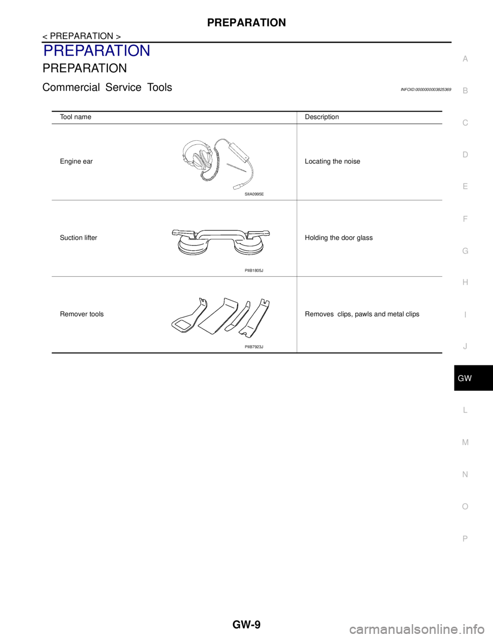
Commercial Service ToolsINFOID:0000000003825369
Tool name Description
Engine ear Locating the noise
Suction lifter Holding the door glass
Remover tools Removes clips, pawls and metal clips
SIIA0995E
PIIB1805J
PIIB7923J
Page 2571 of 5121

HA-2
LOW-PRESSURE PIPE .....................................42
Exploded View ........................................................42
Removal and Installation ........................................42
HIGH-PRESSURE PIPE ....................................44
Exploded View ........................................................44
Removal and Installation ........................................44
CONDENSER ....................................................46
Exploded View ........................................................46
Removal and Installation ........................................46
CONDENSER PIPE ASSEMBLY ......................48
Exploded View ........................................................48
Removal and Installation ........................................48
LIQUID TANK ....................................................50
Exploded View ........................................................50
Removal and Installation ........................................50
REFRIGERANT PRESSURE SENSOR ............51
Exploded View ........................................................51
Removal and Installation ........................................51
EVAPORATOR ..................................................52
Exploded View ........................................................52
Removal and Installation .........................................53
EVAPORATOR PIPE ASSEMBLY ....................54
Exploded View ........................................................54
Removal and Installation .........................................55
EXPANSION VALVE .........................................57
Exploded View ........................................................57
Removal and Installation .........................................58
SERVICE DATA AND SPECIFICATIONS
(SDS) ..........................................................
59
SERVICE DATA AND SPECIFICATIONS
(SDS) .................................................................
59
Compressor ............................................................59
Lubricant .................................................................59
Refrigerant ..............................................................59
Engine Idling Speed ................................................59
Belt Tension ............................................................59