Page 2417 of 5121
EXT-28
< ON-VEHICLE REPAIR >
FLOOR SIDE FAIRING
FLOOR SIDE FAIRING
Exploded ViewINFOID:0000000003819543
Removal and InstallationINFOID:0000000003819544
REMOVAL
ENGINE UNDER COVER
1. Remove engine under cover fixing clips.
2. Remove engine under cover.
INSTALLATION
Install in the reverse order of removal.
1. Engine under cover seal 2. Engine under cover
JMKIA2630ZZ
Page 2464 of 5121
FL-1
ENGINE
C
DE
F
G H
I
J
K L
M
SECTION FL
A
FL
N
O P
CONTENTS
FUEL SYSTEM
PRECAUTION ................ ...............................2
PRECAUTIONS .............................................. .....2
General Precautions ........................................... ......2
PREPARATION ............................................3
PREPARATION .............................................. .....3
Commercial Service Tool .................................... ......3
ON-VEHICLE MAINTENANCE .....................4
FUEL SYSTEM ............................................... .....4
Inspection ............................................................ ......4
Quick Connector .......................................................4
ON-VEHICLE REPAIR ..................................5
FUEL LEVEL SENSOR UNIT, FUEL FILTER
AND FUEL PUMP ASSEMBLY .........................
5
Exploded View ..................................................... .....5
Removal and Installation ..........................................5
Inspection .................................................................8
FUEL TANK ..................................... ..................9
Exploded View ..................................................... .....9
Removal and Installation ..........................................9
Inspection ................................................................10
SERVICE DATA AND SPECIFICATIONS
(SDS) ............... .............................................
11
SERVICE DATA AND SPECIFICATIONS
(SDS) .................................................................
11
Fuel Tank ............................................................. ....11
Page 2465 of 5121
FL-2
< PRECAUTION >
PRECAUTIONS
PRECAUTION
PRECAUTIONS
General PrecautionsINFOID:0000000003793245
WARNING:
When replacing fuel line parts, be sure to observe the following.
• Put a “CAUTION: FLAMMABLE” sign in the workshop.
Be sure to work in a well ventilated area and furnish workshop with a CO
2 fire extinguisher.
Never smoke while servicing fuel system. Keep open flames and sparks away from the work area.
CAUTION:
Use gasoline required by the regulations for octane number. Refer to GI-29, "
Fuel".
Before removing fuel line parts, perform out the following procedures:
- Put drained fuel in an explosion-proof container and put the lid on securely. Keep the container in
safe area.
- Release fuel pressure from the fuel lines. Refer to EC-411, "
Inspection".
- Disconnect the battery cable from the negative terminal.
Always replace O-ring and clamps with new ones.
Never kink or twist tubes when they are being installed.
Never tighten hose clamps excessively to avoid damaging hoses.
After installing tubes, check there is no fuel leakage at connections in the following steps.
- Apply fuel pressure to fuel lines with turning ignition switch “ON” (with engine stopped). Then check
for fuel leakage at connections.
- Start engine and rev it up and check for fuel leakage at connections.
Use only a genuine NISSAN fuel filler cap as a replacement. If an incorrect fuel filler cap is used, the
“MI” may come on.
For servicing “Evaporative Emission System” parts, refer to EC-76, "
System Diagram".
Page 2467 of 5121
FL-4
< ON-VEHICLE MAINTENANCE >
FUEL SYSTEM
ON-VEHICLE MAINTENANCE
FUEL SYSTEM
InspectionINFOID:0000000003793248
Inspect fuel lines, fuel filler cap and fuel tank for improper attach-
ment, leakage, cracks, damage, loose connections, chafing or dete-
rioration.
If necessary, repair or replace damaged parts.
Quick ConnectorINFOID:0000000003793249
CAUTION:
After connecting fuel tube quick connectors, check quick con-
nectors are secure.
Ensure that connector and resin tube never contact any adja-
cent parts.
A : Engine
B : Fuel line
C: Fuel tank
JPBIA0129ZZ
1 : Quick connector
2: Retainer
A : Hard tube (or the equivalent)
B : Connection (cross-section)
C : Resin tube
D : To under floor fuel line
E : To fuel tank
F: Tab
G : Disconnection
JPBIA0130ZZ
Page 2471 of 5121
FL-8
< ON-VEHICLE REPAIR >
FUEL LEVEL SENSOR UNIT, FUEL FILTER AND FUEL PUMP ASSEMBLY
INSTALLATION
Note to the following, and install in the reverse order of removal.
Fuel Level Sensor Unit
1. Install new seal packing to fuel tank without any twist.
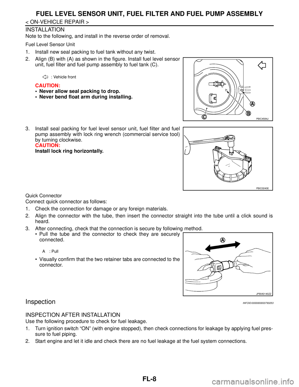
2. Align (B) with (A) as shown in the figure. Install fuel level sensor
unit, fuel filter and fuel pump assembly to fuel tank (C).
CAUTION:
Never allow seal packing to drop.
Never bend float arm during installing.
3. Install seal packing for fuel level sensor unit, fuel filter and fuel
pump assembly with lock ring wrench (commercial service tool)
by turning clockwise.
CAUTION:
Install lock ring horizontally.
Quick Connector
Connect quick connector as follows:
1. Check the connection for damage or any foreign materials.
2. Align the connector with the tube, then insert the connector straight into the tube until a click sound is
heard.
3. After connecting, check that the connection is secure by following method.
Pull the tube and the connector to check they are securely
connected.
Visually confirm that the two retainer tabs are connected to the
connector.
InspectionINFOID:0000000003793253
INSPECTION AFTER INSTALLATION
Use the following procedure to check for fuel leakage.
1. Turn ignition switch “ON” (with engine stopped), then check connections for leakage by applying fuel pres-
sure to fuel piping.
2. Start engine and let it idle and check there are no fuel leakage at the fuel system connections.
: Vehicle front
PBIC4584J
PBIC0240E
A: Pull
JPBIA0140ZZ
Page 2473 of 5121
FL-10
< ON-VEHICLE REPAIR >
FUEL TANK
4. Remove rear parking brake cables. Refer to PB-5, "Exploded View".
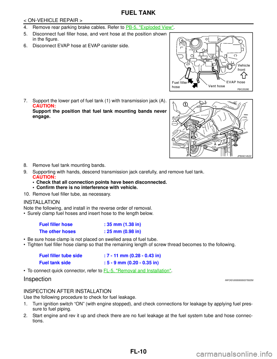
5. Disconnect fuel filler hose, and vent hose at the position shown
in the figure.
6. Disconnect EVAP hose at EVAP canister side.
7. Support the lower part of fuel tank (1) with transmission jack (A).
CAUTION:
Support the position that fuel tank mounting bands never
engage.
8. Remove fuel tank mounting bands.
9. Supporting with hands, descend transmission jack carefully, and remove fuel tank.
CAUTION:
Check that all connection points have been disconnected.
Confirm there is no interference with vehicle.
10. Remove fuel filler tube, as necessary.
INSTALLATION
Note the following, and install in the reverse order of removal.
Surely clamp fuel hoses and insert hose to the length below.
Be sure hose clamp is not placed on swelled area of fuel tube.
Tighten fuel filler hose clamp so that the remaining length of screw thread becomes to the following.
To connect quick connector, refer to FL-5, "
Removal and Installation".
InspectionINFOID:0000000003793256
INSPECTION AFTER INSTALLATION
Use the following procedure to check for fuel leakage.
1. Turn ignition switch “ON” (with engine stopped), and check connections for leakage by applying fuel pres-
sure to fuel piping.
2. Start engine and rev it up and check there are no fuel leakage at the fuel system tube and hose connec-
tions.
PBIC2528E
JPBIA0145ZZ
Fuel filler hose : 35 mm (1.38 in)
The other hoses : 25 mm (0.98 in)
Fuel filler tube side : 7 - 11 mm (0.28 - 0.43 in)
Fuel tank side : 5 - 9 mm (0.20 - 0.35 in)
Page 2478 of 5121
FSU-4
< PRECAUTION >
PRECAUTIONS
Precaution for Procedure without Cowl Top Cover
INFOID:0000000003890157
When performing the procedure after removing cowl top cover, cover
the lower end of windshield with urethane, etc.
Precautions for SuspensionINFOID:0000000003811111
CAUTION:
When installing rubber bushings, the final tightening must be carried out under unladen conditions
with tires on ground. Oil might shorten the life of rubber bushings. Be sure to wipe off any spilled oil.
- Unladen conditions mean that fuel, engine coolant and lubricant are full. Spare tire, jack, hand tools
and mats are in designated positions.
After servicing suspension parts, be sure to check wheel alignment.
Self-lock nuts are not reusable. Always use new ones when installing. Since new self-lock nuts are
pre-oiled, tighten as they are.
PIIB3706J
Page 2481 of 5121
WHEEL ALIGNMENT
FSU-7
< ON-VEHICLE MAINTENANCE >
C
D
F
G
H
I
J
K
L
MA
B
FSU
N
O
P
WHEEL ALIGNMENT
Wheel Alignment InspectionINFOID:0000000003812473
INSPECTION
Description
CAUTION:
Camber, caster, kingpin inclination angles cannot be adjusted.
If camber, caster, or kingpin inclination angle exceeds the standard value, check front suspension
parts for wear and damage. Replace suspect parts if a malfunction is detected.
Kingpin inclination angle is reference value, no inspection is required.
Measure wheel alignment under unladen conditions.
NOTE:
“Unladen conditions” means that fuel, engine coolant, and lubricant are full. Spare tire, jack, hand tools and
mats are in designated positions.
Preliminary Check
Check the following:
Tires for improper air pressure and wear
Road wheels for runout: Refer to WT-2, "
Inspection".
Wheel bearing axial end play: Refer to FA X - 6 , "
Inspection".
Transverse link ball joint axial end play: Refer to FSU-11, "
Inspection".
Strut operation.
Each mounting part of axle and suspension for looseness and deformation
Each of suspension member and transverse link for cracks, deformation and other damage
Vehicle height (posture)
CAMBER, CASTER, AND KINGPIN INCLINATION ANGLES
Camber, caster, kingpin inclination angles cannot be adjusted.
Before inspection, mount front wheels onto turning radius gauge. Mount rear wheels onto a stand at the
same height so that vehicle remains horizontal.
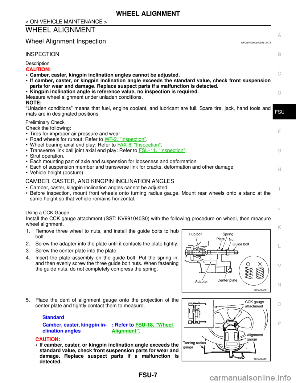
Using a CCK Gauge
Install the CCK gauge attachment (SST: KV991040S0) with the following procedure on wheel, then measure
wheel alignment.
1. Remove three wheel to nuts, and install the guide bolts to hub
bolt.
2. Screw the adapter into the plate until it contacts the plate tightly.
3. Screw the center plate into the plate.
4. Insert the plate assembly on the guide bolt. Put the spring in,
and then evenly screw the three guide bolt nuts. When fastening
the guide nuts, do not completely compress the spring.
5. Place the dent of alignment gauge onto the projection of the
center plate and tightly contact them to measure.
CAUTION:
If camber, caster, or kingpin inclination angle exceeds the
standard value, check front suspension parts for wear and
damage. Replace suspect parts if a malfunction is
detected.
SEIA0240E
Standard
Camber, caster, kingpin in-
clination angles: Refer to FSU-18, "
Wheel
Alignment".
SEIA0241E