2008 NISSAN TEANA engine
[x] Cancel search: enginePage 2577 of 5121
HA-8
< SYMPTOM DIAGNOSIS >
REFRIGERATION SYSTEM SYMPTOMS
SYMPTOM DIAGNOSIS
REFRIGERATION SYSTEM SYMPTOMS
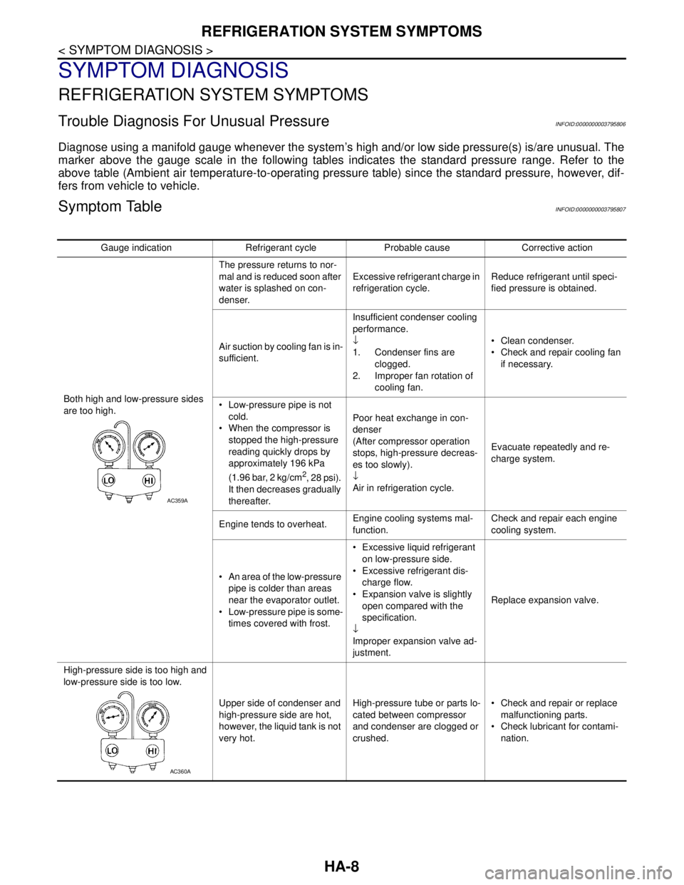
Trouble Diagnosis For Unusual PressureINFOID:0000000003795806
Diagnose using a manifold gauge whenever the system’s high and/or low side pressure(s) is/are unusual. The
marker above the gauge scale in the following tables indicates the standard pressure range. Refer to the
above table (Ambient air temperature-to-operating pressure table) since the standard pressure, however, dif-
fers from vehicle to vehicle.
Symptom TableINFOID:0000000003795807
Gauge indication Refrigerant cycle Probable cause Corrective action
Both high and low-pressure sides
are too high.The pressure returns to nor-
mal and is reduced soon after
water is splashed on con-
denser.Excessive refrigerant charge in
refrigeration cycle.Reduce refrigerant until speci-
fied pressure is obtained.
Air suction by cooling fan is in-
sufficient.Insufficient condenser cooling
performance.
↓
1. Condenser fins are
clogged.
2. Improper fan rotation of
cooling fan. Clean condenser.
Check and repair cooling fan
if necessary.
Low-pressure pipe is not
cold.
When the compressor is
stopped the high-pressure
reading quickly drops by
approximately 196 kPa
(1.96 bar, 2 kg/cm
2, 28 psi).
It then decreases gradually
thereafter.Poor heat exchange in con-
denser
(After compressor operation
stops, high-pressure decreas-
es too slowly).
↓
Air in refrigeration cycle.Evacuate repeatedly and re-
charge system.
Engine tends to overheat.Engine cooling systems mal-
function.Check and repair each engine
cooling system.
An area of the low-pressure
pipe is colder than areas
near the evaporator outlet.
Low-pressure pipe is some-
times covered with frost. Excessive liquid refrigerant
on low-pressure side.
Excessive refrigerant dis-
charge flow.
Expansion valve is slightly
open compared with the
specification.
↓
Improper expansion valve ad-
justment.Replace expansion valve.
High-pressure side is too high and
low-pressure side is too low.
Upper side of condenser and
high-pressure side are hot,
however, the liquid tank is not
very hot.High-pressure tube or parts lo-
cated between compressor
and condenser are clogged or
crushed. Check and repair or replace
malfunctioning parts.
Check lubricant for contami-
nation.
AC359A
AC360A
Page 2588 of 5121

COMPRESSOR
HA-19
< PRECAUTION >
C
D
E
F
G
H
J
K
L
MA
B
HA
N
O
P
COMPRESSOR
General PrecautionsINFOID:0000000003795891
CAUTION:
Plug all openings to prevent moisture and foreign matter from entering.
Store it in the same way at it is when mounted on the car when the compressor is removed.
Follow “Maintenance of Lubricant Quantity in Compressor” exactly when replacing or repairing
compressor. Refer to HA-28, "
Maintenance of Lubricant Quantity".
Keep friction surfaces between clutch and pulley clean. Wipe it off by using a clean waste cloth
moistened with thinner if the surface is contaminated with lubricant.
Turn the compressor shaft by hand more than five turns in both directions after compressor service
operation. This distributes equally lubricant inside the compressor. Let the engine idle and operate
the compressor for one hour after the compressor is installed.
Apply voltage to the new one and check for normal operation after replacing the compressor magnet
clutch.
Page 2589 of 5121

HA-20
< PRECAUTION >
FLUORESCENT LEAK DETECTOR
FLUORESCENT LEAK DETECTOR
General PrecautionsINFOID:0000000003795892
CAUTION:
The A/C system contains a fluorescent leak detection dye used for locating refrigerant leakages. An
ultraviolet (UV) lamp is required to illuminate the dye when inspecting for leakages.
Wear always fluorescence enhancing UV safety goggles to protect eyes and enhance the visibility of
the fluorescent dye.
The fluorescent dye leak detector is not a replacement for an electrical leak detector (SST). The fluo-
rescent dye leak detector should be used in conjunction with an electrical leak detector (SST) to pin-
point refrigerant leakages.
Read and follow all manufacture’s operating instructions and precautions prior to performing the
work for the purpose of safety and customer’s satisfaction.
A compressor shaft seal should not necessarily be repaired because of dye seepage. The compres-
sor shaft seal should only be repaired after confirming the leakage with an electrical leak detector
(SST).
Remove always any remaining dye from the leakage area after repairs are completed to avoid a mis-
diagnosis during a future service.
Never allow dye to come into contact with painted body panels or interior components. Clean imme-
diately with the approved dye cleaner if dye is spilled. Fluorescent dye left on a surface for an
extended period of time cannot be removed.
Never spray the fluorescent dye cleaning agent on hot surfaces (engine exhaust manifold, etc.).
Never use more than one refrigerant dye bottle (1/4 ounce /7.4 cc) per A/C system.
Leak detection dyes for HFC-134a (R-134a) and CFC-12 (R-12) A/C systems are different. Never use
HFC-134a (R-134a) leak detection dye in CFC-12 (R-12) A/C system, or CFC-12 (R-12) leak detection
dye in HFC-134a (R-134a) A/C system, or A/C system damage may result.
The fluorescent properties of the dye remains for three or more years unless a compressor malfunc-
tion occurs.
IDENTIFICATION
NOTE:
Vehicles with factory installed fluorescent dye have a green label.
Vehicles without factory installed fluorescent dye have a blue label.
IDENTIFICATION LABEL FOR VEHICLE
Vehicles with factory installed fluorescent dye have the identification label on the front side of hood.
Page 2594 of 5121
REFRIGERANT
HA-25
< ON-VEHICLE MAINTENANCE >
C
D
E
F
G
H
J
K
L
MA
B
HA
N
O
P
WARNING:
Never breath A/C refrigerant and lubricant vapor or mist. Exposure may irritate eyes, nose and throat.
Use only approved recovery/recycling recharging equipment to discharge HFC-134a (R-134a) refriger-
ant. Ventilate work area before resuming service if accidental system discharge occurs. Additional
health and safety information may be obtained from refrigerant and lubricant manufacturers.
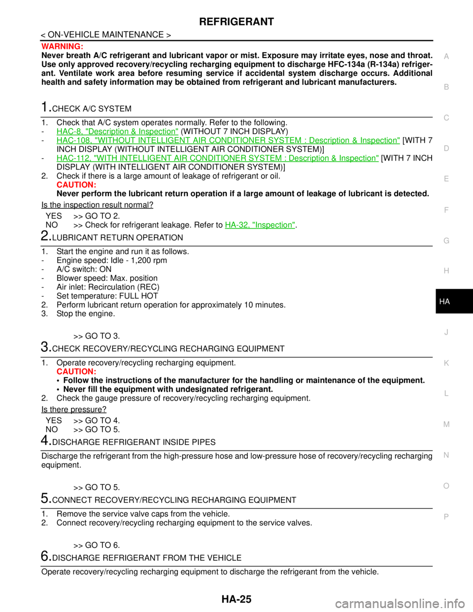
1.CHECK A/C SYSTEM
1. Check that A/C system operates normally. Refer to the following.
-HAC-8, "
Description & Inspection" (WITHOUT 7 INCH DISPLAY)
-HAC-108, "
WITHOUT INTELLIGENT AIR CONDITIONER SYSTEM : Description & Inspection" [WITH 7
INCH DISPLAY (WITHOUT INTELLIGENT AIR CONDITIONER SYSTEM)]
-HAC-112, "
WITH INTELLIGENT AIR CONDITIONER SYSTEM : Description & Inspection" [WITH 7 INCH
DISPLAY (WITH INTELLIGENT AIR CONDITIONER SYSTEM)]
2. Check if there is a large amount of leakage of refrigerant or oil.
CAUTION:
Never perform the lubricant return operation if a large amount of leakage of lubricant is detected.
Is the inspection result normal?
YES >> GO TO 2.
NO >> Check for refrigerant leakage. Refer to HA-32, "
Inspection".
2.LUBRICANT RETURN OPERATION
1. Start the engine and run it as follows.
- Engine speed: Idle - 1,200 rpm
- A/C switch: ON
- Blower speed: Max. position
- Air inlet: Recirculation (REC)
- Set temperature: FULL HOT
2. Perform lubricant return operation for approximately 10 minutes.
3. Stop the engine.
>> GO TO 3.
3.CHECK RECOVERY/RECYCLING RECHARGING EQUIPMENT
1. Operate recovery/recycling recharging equipment.
CAUTION:
Follow the instructions of the manufacturer for the handling or maintenance of the equipment.
Never fill the equipment with undesignated refrigerant.
2. Check the gauge pressure of recovery/recycling recharging equipment.
Is there pressure?
YES >> GO TO 4.
NO >> GO TO 5.
4.DISCHARGE REFRIGERANT INSIDE PIPES
Discharge the refrigerant from the high-pressure hose and low-pressure hose of recovery/recycling recharging
equipment.
>> GO TO 5.
5.CONNECT RECOVERY/RECYCLING RECHARGING EQUIPMENT
1. Remove the service valve caps from the vehicle.
2. Connect recovery/recycling recharging equipment to the service valves.
>> GO TO 6.
6.DISCHARGE REFRIGERANT FROM THE VEHICLE
Operate recovery/recycling recharging equipment to discharge the refrigerant from the vehicle.
Page 2597 of 5121
HA-28
< ON-VEHICLE MAINTENANCE >
LUBRICANT
LUBRICANT
Maintenance of Lubricant QuantityINFOID:0000000003795916
The lubricant in the compressor circulates through the system the refrigerant. Add lubricant to compressor
when replacing any component or after a large refrigerant leakage occurred. It is important to maintain the
specified amount.
If lubricant quantity is not maintained properly, the following malfunctions may result:
Lack of lubricant: May lead to a seized compressor.
Excessive lubricant: Inadequate cooling (thermal exchange interference)
LUBRICANT
LUBRICANT RETURN OPERATION
Adjust the lubricant quantity according to the test group shown below.
1.CHECK LUBRICANT RETURN OPERATION
Can lubricant return operation be performed?
A/C system works normally.
There is no evidence of a large amount of lubricant leakage.
CAUTION:
Never perform the lubricant return operation if excessive lubricant leakage is detected.
Is it successful?
YES >> GO TO 2.
NO >> GO TO 3.
2.PERFORM LUBRICANT RETURN OPERATION
1. Start the engine, and set to the following conditions:
- Engine speed: Idling to 1,200 rpm
- A/C switch: ON
- Blower speed: Max. position
- Set temperature: FULL HOT
- Intake position: Recirculation (REC)
2. Perform lubricant return operation for approximately 10 minutes.
3. Stop the engine.
>> GO TO 3.
3.CHECK REPLACEMENT PART
Should the compressor be replaced?
YES >> Refer to HA-29, "Lubricant Adjusting Procedure for Compressor Replacement".
NO >> Refer to HA-28, "
Lubricant Adjusting Procedure for Components Replacement Except Compres-
sor".
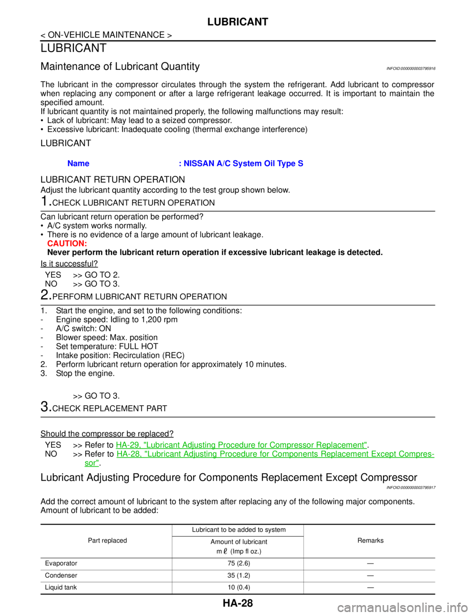
Lubricant Adjusting Procedure for Components Replacement Except Compressor
INFOID:0000000003795917
Add the correct amount of lubricant to the system after replacing any of the following major components.
Amount of lubricant to be added:Name : NISSAN A/C System Oil Type S
Part replacedLubricant to be added to system
Remarks
Amount of lubricant
m (Imp fl oz.)
Evaporator 75 (2.6) —
Condenser 35 (1.2) —
Liquid tank 10 (0.4) —
Page 2599 of 5121
HA-30
< ON-VEHICLE MAINTENANCE >
REFRIGERATION SYSTEM
REFRIGERATION SYSTEM
InspectionINFOID:0000000003795977
1.CHECK BLOWER MOTOR OPERATION
Check blower motor operation. Refer to the following.
HAC-68, "
ComponentFunctionCheck" (WITHOUT 7 INCH DISPLAY)
HAC-193, "
ComponentFunctionCheck" (WITH 7 INCH DISPLAY)
Is the inspection result normal?
YES >> GO TO 2.
NO >> Repair or replace the parts according to the inspection results.
2.CHECK COMPRESSOR OPERATION
Check compressor operation. Refer to the following.
HAC-72, "
Component Function Check" (WITHOUT 7 INCH DISPLAY)
HAC-197, "
Component Function Check" (WITH 7 INCH DISPLAY)
Is the inspection result normal?
YES >> GO TO 3.
NO >> Repair or replace the parts according to the inspection results.
3.CHECK REFRIGERANT CYCLE PRESSURE
Connect recovery/recycling recharging equipment to the vehicle and perform the diagnosis with the gauge
pressure. Refer to HA-8, "
Trouble Diagnosis For Unusual Pressure".
Is the inspection result normal?
YES >> Perform the performance test. Refer to HA-30, "Performance Chart".
NO >> Repair or replace the parts according to the inspection results.
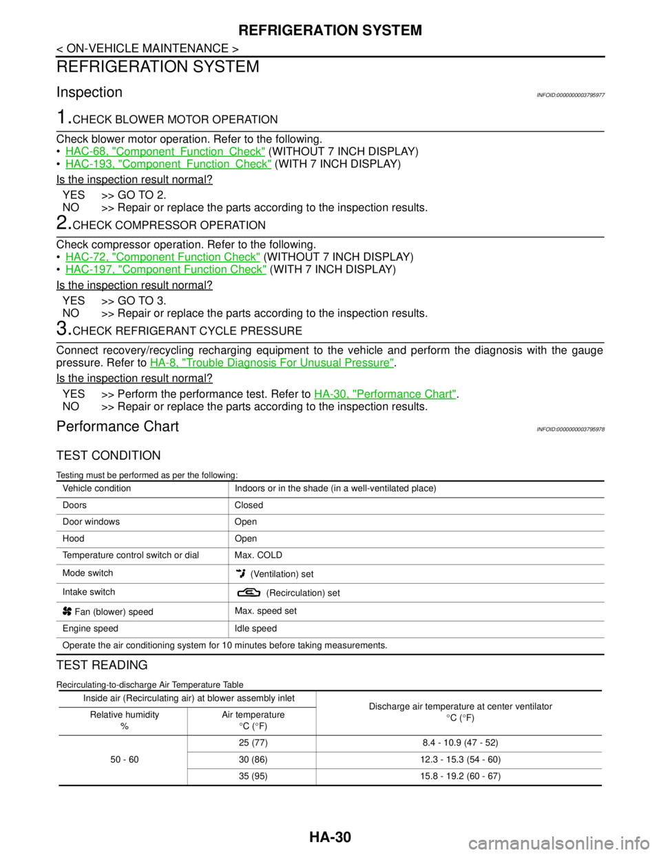
Performance ChartINFOID:0000000003795978
TEST CONDITION
Testing must be performed as per the following:
TEST READING
Recirculating-to-discharge Air Temperature Table
Vehicle condition Indoors or in the shade (in a well-ventilated place)
Doors Closed
Door windows Open
Hood Open
Temperature control switch or dial Max. COLD
Mode switch
(Ventilation) set
Intake switch
(Recirculation) set
Fan (blower) speedMax. speed set
Engine speed Idle speed
Operate the air conditioning system for 10 minutes before taking measurements.
Inside air (Recirculating air) at blower assembly inlet
Discharge air temperature at center ventilator
°C (°F) Relative humidity
%Air temperature
°C (°F)
50 - 6025 (77) 8.4 - 10.9 (47 - 52)
30 (86) 12.3 - 15.3 (54 - 60)
35 (95) 15.8 - 19.2 (60 - 67)
Page 2601 of 5121

HA-32
< ON-VEHICLE MAINTENANCE >
FLUORESCENT LEAK DETECTOR
FLUORESCENT LEAK DETECTOR
InspectionINFOID:0000000003795981
CHECKING SYSTEM FOR LEAKAGES USING THE FLUORESCENT LEAK DETECTOR
1. Check A/C system for leakages using the UV lamp and safety goggles (SST: J-42220) in a low sunlight
area (area without windows preferable). Illuminate all components, fittings and lines. The dye appears as
a bright green/yellow area at the point of leakage. Fluorescent dye observed at the evaporator drain open-
ing indicates an evaporator core assembly (tubes, core or expansion valve) leakage.
2. Use an adjustable mirror or wipe the area with a clean shop rag or cloth, with the UV lamp for dye residue
if the suspected area is difficult to see.
3. Remove any residual dye using dye cleaner (SST: J-43872) to prevent future misdiagnosis after the leak-
age is repaired.
4. Perform a system performance check and verify the leakage repair with an approved electrical leak detec-
tor.
NOTE:
Other gases in the work area or substances on the A/C components, for example, anti-freeze, windshield
washer fluid, solvents and lubricants, may falsely trigger the leak detector. Make sure the surfaces to be
checked are clean.
Clean with a dry cloth or blow off with shop air.
Do not allow the sensor tip of the detector to contact with any substance. This may also cause false readings
and may damage the detector.
DYE INJECTION
(This procedure is only necessary when recharging the system or when the compressor has seized and was
replaced.)
1. Check A/C system static (at rest) pressure. Pressure must be at least 345 kPa (3.45 bar, 3.52 kg/cm
2, 50
psi).
2. Pour one bottle (1/4 ounce / 7.4 cc) of the A/C refrigerant dye into the injector tool (SST: J-41459).
3. Connect the injector tool to the A/C low-pressure side service valve.
4. Start the engine. Then switch A/C ON.
5. Inject one bottle (1/4 ounce / 7.4 cc) of fluorescent dye through the low-pressure service valve using dye
injector tool (SST: J-41459) (refer to the manufacture’s operating instructions) when the A/C operating
(compressor running).
6. Disconnect the injector tool from the service valve with the engine still running.
CAUTION:
Be careful when replacing the A/C system or a component, pour the dye directly into the open sys-
tem connection and proceed with the service procedures.
7. Operate the A/C system for a minimum of 20 minutes to mix the dye with the system oil. Depending on the
leakage size, operating conditions and location of the leakage, it may take from minutes to days for the
dye to penetrate a leakage and become visible.
8. Attach a blue label if necessary.
Page 2602 of 5121
ELECTRICAL LEAK DETECTOR
HA-33
< ON-VEHICLE MAINTENANCE >
C
D
E
F
G
H
J
K
L
MA
B
HA
N
O
P
ELECTRICAL LEAK DETECTOR
InspectionINFOID:0000000003795982
PRECAUTIONS FOR HANDLING LEAK DETECTOR
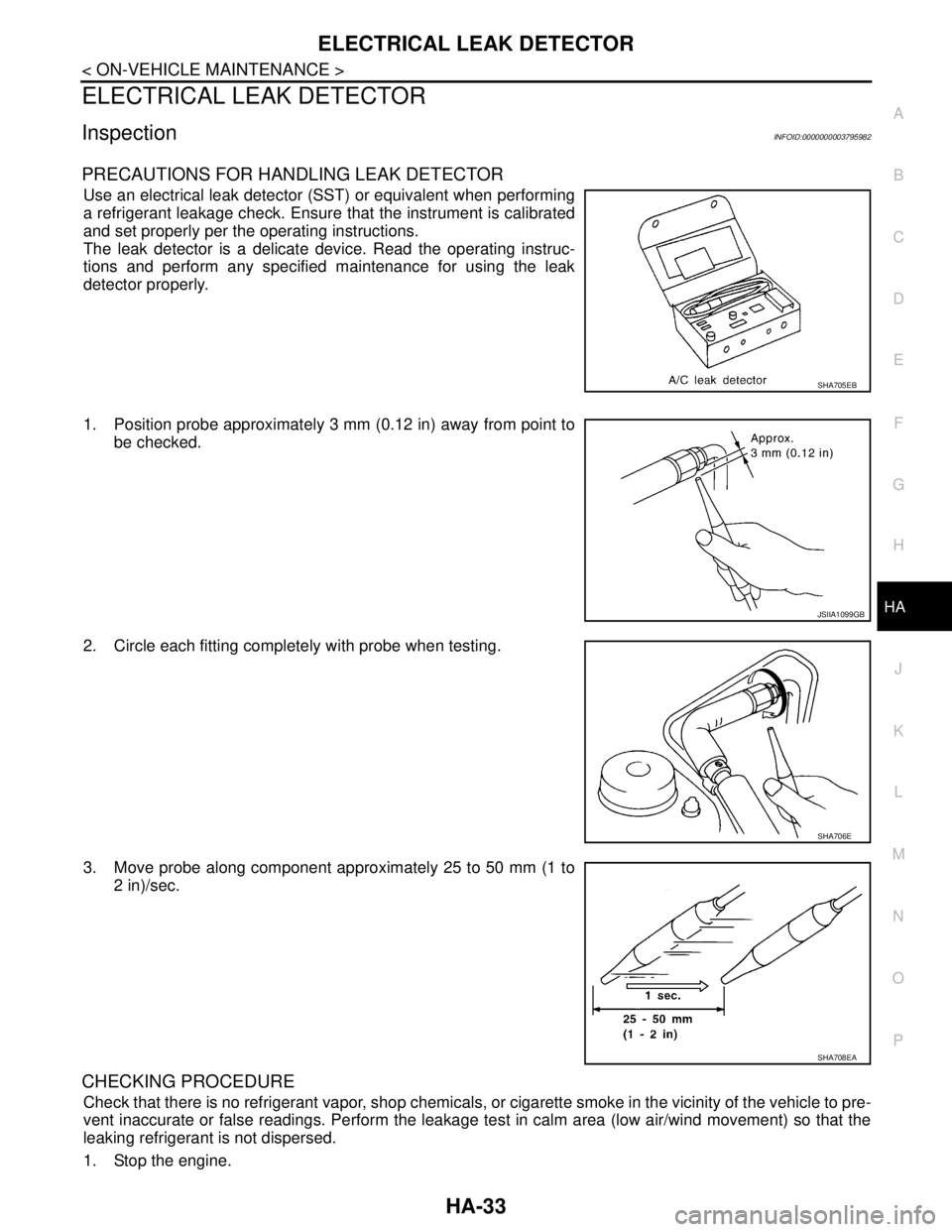
Use an electrical leak detector (SST) or equivalent when performing
a refrigerant leakage check. Ensure that the instrument is calibrated
and set properly per the operating instructions.
The leak detector is a delicate device. Read the operating instruc-
tions and perform any specified maintenance for using the leak
detector properly.
1. Position probe approximately 3 mm (0.12 in) away from point to
be checked.
2. Circle each fitting completely with probe when testing.
3. Move probe along component approximately 25 to 50 mm (1 to
2 in)/sec.
CHECKING PROCEDURE
Check that there is no refrigerant vapor, shop chemicals, or cigarette smoke in the vicinity of the vehicle to pre-
vent inaccurate or false readings. Perform the leakage test in calm area (low air/wind movement) so that the
leaking refrigerant is not dispersed.
1. Stop the engine.
SHA705EB
JSIIA1099GB
SHA706E
SHA708EA