Page 2603 of 5121

HA-34
< ON-VEHICLE MAINTENANCE >
ELECTRICAL LEAK DETECTOR
2. Connect a suitable A/C manifold gauge set (SST) to the A/C service valves.
3. Check if the A/C refrigerant pressure is at least 345 kPa (3.45 bar, 3.52 kg/cm
2, 50 psi) above 16°C
(61°F). Recover/evacuate and recharge the system with the specified amount of refrigerant if less than
specification.
NOTE:
Leakages may not be detected since the system may not reach 345 kPa (3.45 bar, 3.52 kg/cm
2, 50 psi) at
temperatures below 16°C (61°F).
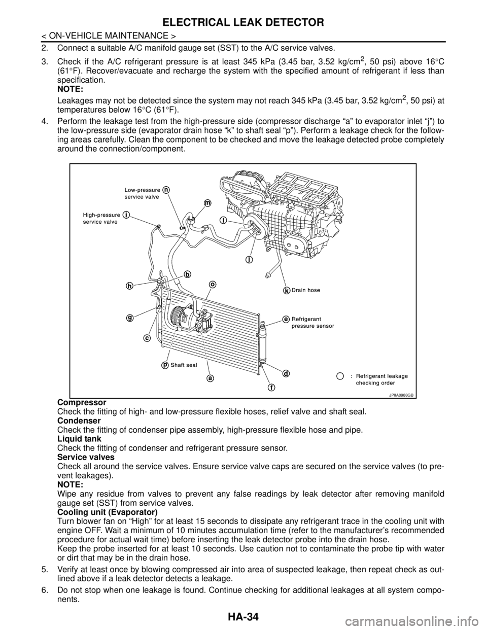
4. Perform the leakage test from the high-pressure side (compressor discharge “a” to evaporator inlet “j”) to
the low-pressure side (evaporator drain hose “k” to shaft seal “p”). Perform a leakage check for the follow-
ing areas carefully. Clean the component to be checked and move the leakage detected probe completely
around the connection/component.
Compressor
Check the fitting of high- and low-pressure flexible hoses, relief valve and shaft seal.
Condenser
Check the fitting of condenser pipe assembly, high-pressure flexible hose and pipe.
Liquid tank
Check the fitting of condenser and refrigerant pressure sensor.
Service valves
Check all around the service valves. Ensure service valve caps are secured on the service valves (to pre-
vent leakages).
NOTE:
Wipe any residue from valves to prevent any false readings by leak detector after removing manifold
gauge set (SST) from service valves.
Cooling unit (Evaporator)
Turn blower fan on “High” for at least 15 seconds to dissipate any refrigerant trace in the cooling unit with
engine OFF. Wait a minimum of 10 minutes accumulation time (refer to the manufacturer’s recommended
procedure for actual wait time) before inserting the leak detector probe into the drain hose.
Keep the probe inserted for at least 10 seconds. Use caution not to contaminate the probe tip with water
or dirt that may be in the drain hose.
5. Verify at least once by blowing compressed air into area of suspected leakage, then repeat check as out-
lined above if a leak detector detects a leakage.
6. Do not stop when one leakage is found. Continue checking for additional leakages at all system compo-
nents.
JPIIA0988GB
Page 2604 of 5121

ELECTRICAL LEAK DETECTOR
HA-35
< ON-VEHICLE MAINTENANCE >
C
D
E
F
G
H
J
K
L
MA
B
HA
N
O
P
If no leakages are found, perform steps 7 - 10.
7. Start the engine.
8. Set the A/C control as per the following;
a. A/C switch: ON
b. Air flow: VENT (Ventilation)
c. Intake door position: Recirculation
d. Temperature setting: Max. cold
e. Fan speed: High
9. Run engine at 1,500 rpm for at least 2 minutes.
10. Stop the engine and perform leakage check again following
steps 4 through 6 above.
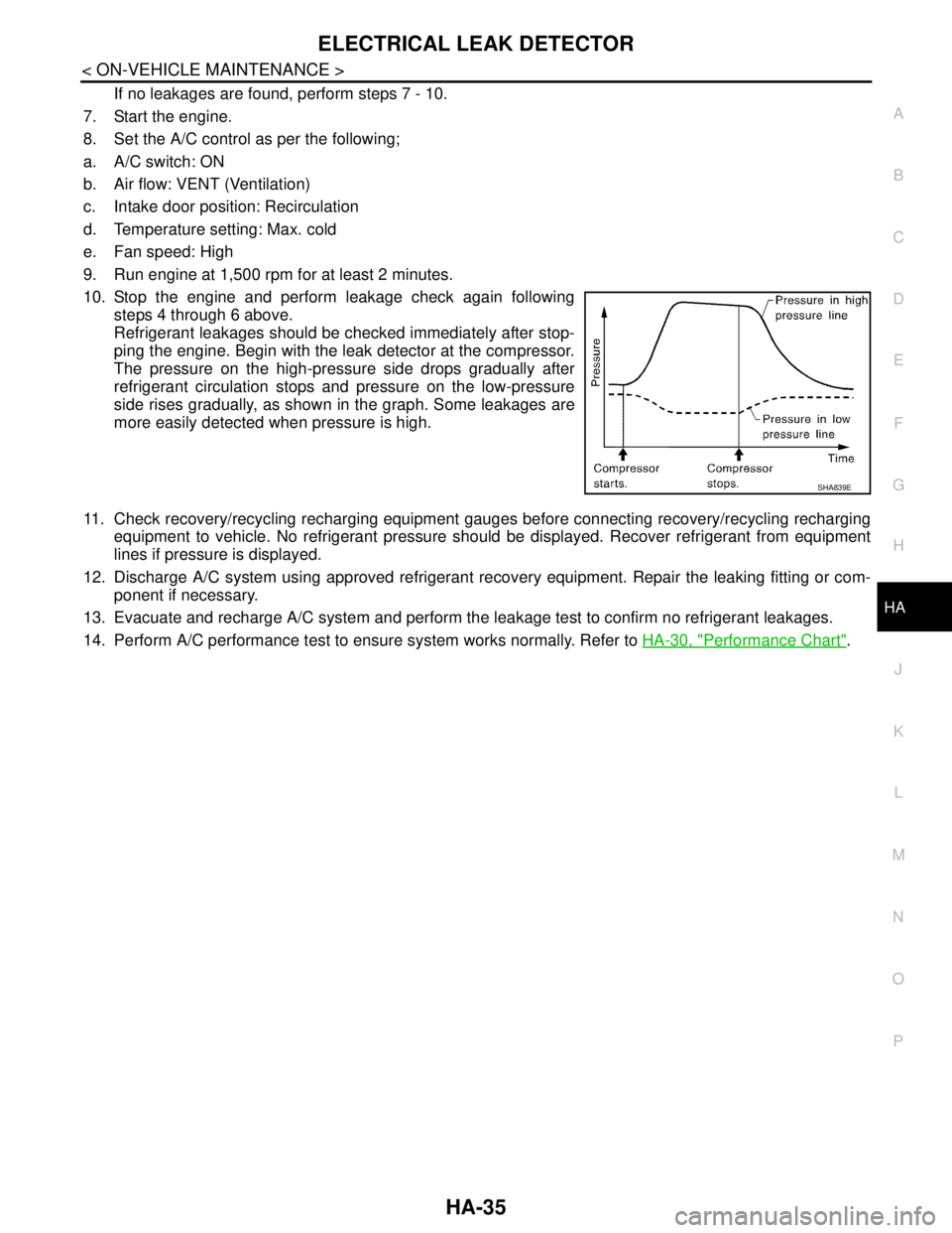
Refrigerant leakages should be checked immediately after stop-
ping the engine. Begin with the leak detector at the compressor.
The pressure on the high-pressure side drops gradually after
refrigerant circulation stops and pressure on the low-pressure
side rises gradually, as shown in the graph. Some leakages are
more easily detected when pressure is high.
11. Check recovery/recycling recharging equipment gauges before connecting recovery/recycling recharging
equipment to vehicle. No refrigerant pressure should be displayed. Recover refrigerant from equipment
lines if pressure is displayed.
12. Discharge A/C system using approved refrigerant recovery equipment. Repair the leaking fitting or com-
ponent if necessary.
13. Evacuate and recharge A/C system and perform the leakage test to confirm no refrigerant leakages.
14. Perform A/C performance test to ensure system works normally. Refer to HA-30, "
Performance Chart".
SHA839E
Page 2628 of 5121
SERVICE DATA AND SPECIFICATIONS (SDS)
HA-59
< SERVICE DATA AND SPECIFICATIONS (SDS)
C
D
E
F
G
H
J
K
L
MA
B
HA
N
O
P
SERVICE DATA AND SPECIFICATIONS (SDS)
SERVICE DATA AND SPECIFICATIONS (SDS)
CompressorINFOID:0000000003795858
LubricantINFOID:0000000003795859
RefrigerantINFOID:0000000003795860
Engine Idling SpeedINFOID:0000000003795861
Refer to EC-414, "Idle Speed".
Belt TensionINFOID:0000000003795862
Refer to EM-136, "Drive Belt".
ModelVALEO THERMAL SYSTEMS JAPAN make
DKS-17D
Ty p eFixation displacement swash plate
Displacement
cm
3 (cu in)/revMax. 175 (10.7)
Cylinder bore × stroke (Max.)
mm (in.)30.5 (1.21) × 24 (0.95)
Direction of rotationClockwise (viewed from clutch)
Drive beltPoly V
Disc to pulley clearance
mm (in.)Standard 0.3 - 0.6 (0.012 - 0.024)
NameNISSAN A/C System Oil Type S (DH-PS)
Capacity
m (US fl oz, lmp fl oz)Total in system 150 (5.03, 5.3)
Compressor (service part) charging
amount150 (5.03, 5.3)
Ty p eHFC-134a (R-134a)
Capacity
kg (lb)0.55 (1.21)
Page 2636 of 5121
![NISSAN TEANA 2008 Service Manual HAC-8
< BASIC INSPECTION >[WITHOUT 7 INCH DISPLAY]
INSPECTION AND ADJUSTMENT
INSPECTION AND ADJUSTMENT
Description & InspectionINFOID:0000000003846291
DESCRIPTION
The purpose of the operational check NISSAN TEANA 2008 Service Manual HAC-8
< BASIC INSPECTION >[WITHOUT 7 INCH DISPLAY]
INSPECTION AND ADJUSTMENT
INSPECTION AND ADJUSTMENT
Description & InspectionINFOID:0000000003846291
DESCRIPTION
The purpose of the operational check](/manual-img/5/57391/w960_57391-2635.png)
HAC-8
< BASIC INSPECTION >[WITHOUT 7 INCH DISPLAY]
INSPECTION AND ADJUSTMENT
INSPECTION AND ADJUSTMENT
Description & InspectionINFOID:0000000003846291
DESCRIPTION
The purpose of the operational check is to check that the individual system operates normally.
INSPECTION PROCEDURE
1.CHECK MEMORY FUNCTION
1. Start the engine.
2. Operate the temperature control switch (driver side) and raise the temperature setting to 32°C (90°F).
3. Press the OFF switch.
4. Turn the ignition switch OFF.
5. Turn the ignition switch ON.
6. Press the AUTO switch.
7. Check that the temperature setting before turning the ignition switch OFF is stored.
Is the inspection result normal?
YES >> GO TO 2.
NO >> Memory function malfunction: HAC-96, "
Inspection procedure".
2.CHECK BLOWER MOTOR SPEED
1. Start the engine.
2. Operate the fan control dial. Check that the fan speed changes. Check the operation for all fan speeds.
3. Set the fan speed to speed 7.
Is the inspection result normal?
YES >> GO TO 3.
NO >> Blower motor system malfunction: HAC-68, "
Diagnosis Procedure".
3.CHECK DISCHARGE AIR
1. Press the MODE switch and the DEF switch.
2. Each position indicator should change shape.
3. Confirm that discharge air comes out according to the air distribution table. Refer to HAC-17, "
System
Description".
NOTE:
Confirm that the compressor clutch is engaged (sound or visual inspection) and the intake door position is at
the FRE when DEF is selected.
Is the inspection result normal?
YES >> GO TO 4.
NO >> Mode door system malfunction: HAC-61, "
Diagnosis Procedure". Conditions : Engine running at normal operating temperature
JPIIA0877GB
Page 2637 of 5121
![NISSAN TEANA 2008 Service Manual INSPECTION AND ADJUSTMENT
HAC-9
< BASIC INSPECTION >[WITHOUT 7 INCH DISPLAY]
C
D
E
F
G
H
J
K
L
MA
B
HAC
N
O
P
4.CHECK INTAKE AIR
1. Press the REC switch. REC indicator is turned ON.
2. Press the FRE s NISSAN TEANA 2008 Service Manual INSPECTION AND ADJUSTMENT
HAC-9
< BASIC INSPECTION >[WITHOUT 7 INCH DISPLAY]
C
D
E
F
G
H
J
K
L
MA
B
HAC
N
O
P
4.CHECK INTAKE AIR
1. Press the REC switch. REC indicator is turned ON.
2. Press the FRE s](/manual-img/5/57391/w960_57391-2636.png)
INSPECTION AND ADJUSTMENT
HAC-9
< BASIC INSPECTION >[WITHOUT 7 INCH DISPLAY]
C
D
E
F
G
H
J
K
L
MA
B
HAC
N
O
P
4.CHECK INTAKE AIR
1. Press the REC switch. REC indicator is turned ON.
2. Press the FRE switch. FRE indicator is turned ON.
3. Listen for the intake door position change. (Slight change of blower sound can be heard.)
NOTE:
Confirm that the compressor clutch is engaged (sound or visual inspection) and the intake door position is at
the FRE when the DEF is selected.
Is the inspection result normal?
YES >> GO TO 5.
NO >> Intake door system malfunction: HAC-64, "
Diagnosis Procedure".
5.CHECK A/C SWITCH
1. Press the A/C switch.
2. The A/C switch indicator is turned ON.
Confirm that the compressor clutch engages (sound or visual inspection).
Is the inspection result normal?
YES >> GO TO 6.
NO >> Magnet clutch system malfunction: HAC-72, "
Diagnosis Procedure".
6.CHECK WITH TEMPERATURE SETTING LOWERED
1. Operate the compressor.
2. Operate the temperature control switch (driver side) and lower the temperature setting to 18°C (60°F).
3. Check that the cool air blows from the outlets.
Is the inspection result normal?
YES >> GO TO 7.
NO >> Insufficient cooling: HAC-88, "
Inspection procedure".
7.CHECK WITH TEMPERATURE SETTING RAISED
1. Operate the temperature control switch (driver side) and raise the temperature setting to 32°C (90°F) after
warming up the engine.
2. Check that the warm air blows from the outlets.
Is the inspection result normal?
YES >> GO TO 8.
NO >> Insufficient heating: HAC-91, "
Inspection procedure".
8.CHECK LEFT AND RIGHT VENTILATION TEMPERATURE SEPARATELY CONTROL SYSTEM FUNC-
TION
1. Press the DUAL switch, and then check that “DUAL” is shown on the display.
2. Operate the temperature control switch (driver side). Check that the discharge air temperature (driver
side) changes.
3. Operate the temperature control switch (passenger side). Check that the discharge air temperature (pas-
senger side) changes.
4. Press the DUAL switch, and then check that the temperature setting (LH/RH) is unified to the driver side
temperature setting.
Is the inspection result normal?
YES >> GO TO 9.
NO >> Refer to HAC-87, "
Diagnosis Chart By Symptom" and perform the appropriate diagnosis.
9.CHECK AUTO MODE
1. Press the AUTO switch, and then check that “AUTO” is shown on the display.
2. Operate the temperature control switch (driver side). Check that the fan speed or outlet changes (the dis-
charge air temperature or fan speed varies depending on the ambient temperature, in-vehicle tempera-
ture, and temperature setting).
Is the inspection result normal?
YES >> GO TO 10.
NO >> Refer to HAC-87, "
Diagnosis Chart By Symptom" and perform the appropriate diagnosis.
Page 2640 of 5121
HAC-12
< FUNCTION DIAGNOSIS >[WITHOUT 7 INCH DISPLAY]
COMPRESSOR CONTROL FUNCTION
FUNCTION DIAGNOSIS
COMPRESSOR CONTROL FUNCTION
DescriptionINFOID:0000000003846298
PRINCIPLE OF OPERATION
Compressor is not activated.
Functional circuit diagram
Functional initial inspection chart
CAN (1) : A/C switch signal
: Blower fan motor switch signalCAN (2) : A/C Compressor request signal
RX : A/C switch signal
: Fan ON signal
: Defroster signal
JPIIA0483GB
Control unit Diagnosis ItemLocation
ABCD
A/C auto amp.
“HVAC”Self-diagnosis Yes
Data monitor Yes
Active test Yes Yes
ECM
“ENGINE”Self-diagnosis
(CAN system diagnosis)Ye s
Data monitor Yes Yes
IPDM E/R“IPDM E/R”Self-diagnosis
(CAN system diagnosis)Ye s
Data monitor Yes
Auto active testYe s
Page 2641 of 5121
COMPRESSOR CONTROL FUNCTION
HAC-13
< FUNCTION DIAGNOSIS >[WITHOUT 7 INCH DISPLAY]
C
D
E
F
G
H
J
K
L
MA
B
HAC
N
O
P
Fail-SafeINFOID:0000000003901219
FAIL-SAFE FUNCTION
If a communication error exists between the A/C auto amp. and A/C control for 30 seconds or longer, air con-
ditioner is controlled under the following conditions:
Component Part LocationINFOID:0000000003846299
ENGINE COMPARTMENT
Compressor : ON
Air outlet : AUTO
Air inlet : FRE (Fresh)
Blower fan speed : AUTO
Set temperature : Setting before communication error occurs
Page 2652 of 5121
HAC-24
< FUNCTION DIAGNOSIS >[WITHOUT 7 INCH DISPLAY]
AUTOMATIC AIR CONDITIONER SYSTEM
At the end of each transmission, a stop operation, in-operation, or internal malfunction message is delivered
to the A/C auto amp. This completes one data transmission and control cycle.
Component Part LocationINFOID:0000000003846303
ENGINE COMPARTMENT
JSIIA1132GB