2008 NISSAN TEANA engine
[x] Cancel search: enginePage 2490 of 5121

FSU-16
< REMOVAL AND INSTALLATION >
FRONT SUSPENSION MEMBER
REMOVAL AND INSTALLATION
FRONT SUSPENSION MEMBER
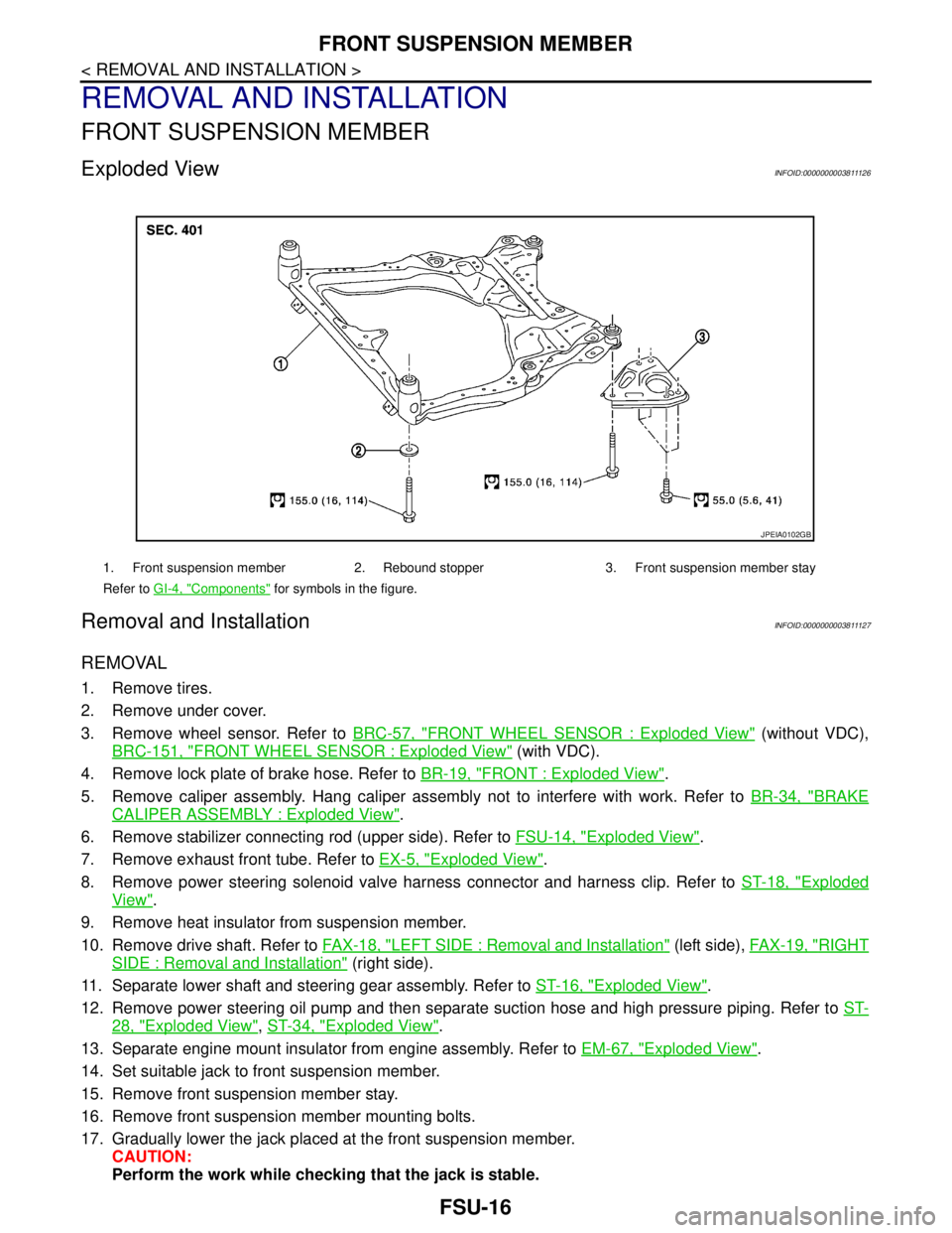
Exploded ViewINFOID:0000000003811126
Removal and InstallationINFOID:0000000003811127
REMOVAL
1. Remove tires.
2. Remove under cover.
3. Remove wheel sensor. Refer to BRC-57, "
FRONT WHEEL SENSOR : Exploded View" (without VDC),
BRC-151, "
FRONT WHEEL SENSOR : Exploded View" (with VDC).
4. Remove lock plate of brake hose. Refer to BR-19, "
FRONT : Exploded View".
5. Remove caliper assembly. Hang caliper assembly not to interfere with work. Refer to BR-34, "
BRAKE
CALIPER ASSEMBLY : Exploded View".
6. Remove stabilizer connecting rod (upper side). Refer to FSU-14, "
Exploded View".
7. Remove exhaust front tube. Refer to EX-5, "
Exploded View".
8. Remove power steering solenoid valve harness connector and harness clip. Refer to ST-18, "
Exploded
View".
9. Remove heat insulator from suspension member.
10. Remove drive shaft. Refer to FAX-18, "
LEFT SIDE : Removal and Installation" (left side), FAX-19, "RIGHT
SIDE : Removal and Installation" (right side).
11. Separate lower shaft and steering gear assembly. Refer to ST-16, "
Exploded View".
12. Remove power steering oil pump and then separate suction hose and high pressure piping. Refer to ST-
28, "Exploded View", ST-34, "Exploded View".
13. Separate engine mount insulator from engine assembly. Refer to EM-67, "
Exploded View".
14. Set suitable jack to front suspension member.
15. Remove front suspension member stay.
16. Remove front suspension member mounting bolts.
17. Gradually lower the jack placed at the front suspension member.
CAUTION:
Perform the work while checking that the jack is stable.
1. Front suspension member 2. Rebound stopper 3. Front suspension member stay
Refer to GI-4, "
Components" for symbols in the figure.
JPEIA0102GB
Page 2491 of 5121

FRONT SUSPENSION MEMBER
FSU-17
< REMOVAL AND INSTALLATION >
C
D
F
G
H
I
J
K
L
MA
B
FSU
N
O
P
NOTE:
Remove the steering knuckle and wheel bearing assembly, steering gear assembly and hydraulic line,
stabilizer bar, transverse link and engine mounting insulator as a unit from the vehicle.
18. Remove the following parts.
Steering knuckle and wheel hub and bearing assembly: refer to FA X - 8 , "
Exploded View".
Steering gear assembly and hydraulic line: refer to ST-18, "
Exploded View" and ST-34, "Exploded
View".
Stabilizer bar: refer to FSU-14, "
Exploded View".
Transverse link: refer to FSU-12, "
Exploded View".
Engine mounting insulator: refer to EM-67, "
Exploded View".
INSTALLATION
Note the following, and install in the reverse order of removal.
Perform final tightening of installation position between front suspension member and transverse links (rub-
ber bushing) under unladen condition with tires on level ground.
InspectionINFOID:0000000003811128
INSPECTION AFTER REMOVAL
Check the front suspension member for significant deformation, cracks, or damages. Replace if necessary.
INSPECTION AFTER INSTALLATION
1. Check wheel sensor harness for proper connection. Refer to BRC-57, "FRONT WHEEL SENSOR :
Exploded View" (without VDC), BRC-151, "FRONT WHEEL SENSOR : Exploded View" (with VDC).
2. Check wheel alignment. Refer to FSU-7, "
Wheel Alignment Inspection".
3. Adjust the neutral position of the steering angle sensor. Refer to BRC-66, "
ADJUSTMENT OF STEERING
ANGLE SENSOR NEUTRAL POSITION : Special Repair Requirement".
Page 2492 of 5121

FSU-18
< SERVICE DATA AND SPECIFICATIONS (SDS)
SERVICE DATA AND SPECIFICATIONS (SDS)
SERVICE DATA AND SPECIFICATIONS (SDS)
SERVICE DATA AND SPECIFICATIONS (SDS)
Wheel AlignmentINFOID:0000000003811129
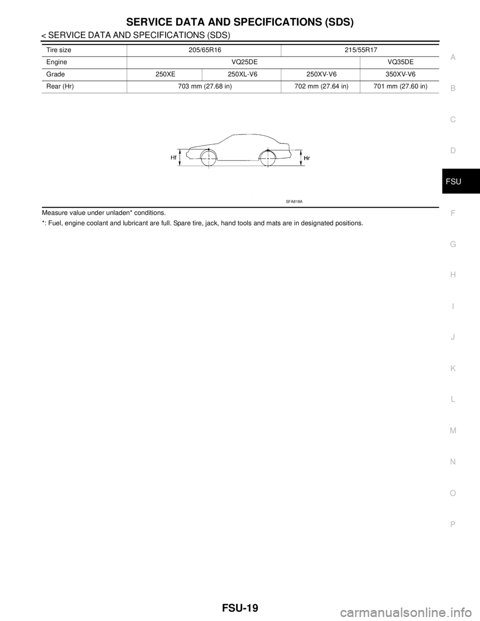
Measure value under unladen* conditions.
*: Fuel, engine coolant and lubricant are full. Spare tire, jack, hand tools and mats are in designated positions.
Ball JointINFOID:0000000003811130
Wheel HeightINFOID:0000000003811131
Item Standard
Camber
Degree minute (Decimal degree)Minimum –1° 10′ (–1.16°)
Nominal –0° 25′ (–0.42°)
Maximum 0° 20′ (0.33°)
Left and right difference 0° 45′ (0.75°) or less
Caster
Degree minute (Decimal degree)Minimum 4° 10′ (4.17°)
Nominal 4° 55′ (4.92°)
Maximum 5° 40′ (5.66°)
Left and right difference 0° 45′ (0.75°) or less
Kingpin inclination
Degree minute (Decimal degree)Minimum 11° 55′ (11.92°)
Nominal 12° 40′ (12.67°)
Maximum 13° 25′ (13.41°)
To t a l t o e -
inDistanceMinimum In 0.5 mm (0.020 in)
Nominal In 1.5 mm (0.059 in)
Maximum In 2.5 mm (0.098 in)
Angle (left wheel or right wheel)
Degree minute (Decimal degree)Minimum In 0° 02′ (0.04°)
Nominal In 0° 04
′ (0.07°)
Maximum In 0° 06′ (0.10°)
Item Standard
Swing torque Transverse link 0.5 – 4.9 N·m (0.06 – 0.49 kg-m, 5 – 43 in-lb)
Measurement on spring balance Transverse link 11.1 – 108.9 N (1.2 – 11.1 kg, 3 – 24 lb)
Rotating torque Transverse link 0.5 – 3.4 N·m (0.06 – 0.34 kg-m, 5 – 30 in-lb)
Axial end play0.1 mm (0.004 in)
Tire size 205/65R16 215/55R17
Engine VQ25DE VQ35DE
Grade 250XE 250XL-V6 250XV-V6 350XV-V6
Front (Hf) 712 mm (28.03 in) 711 mm (27.99 in) 710 mm (27.95 in)
Page 2493 of 5121

SERVICE DATA AND SPECIFICATIONS (SDS)
FSU-19
< SERVICE DATA AND SPECIFICATIONS (SDS)
C
D
F
G
H
I
J
K
L
MA
B
FSU
N
O
P
Measure value under unladen* conditions.
*: Fuel, engine coolant and lubricant are full. Spare tire, jack, hand tools and mats are in designated positions.Rear (Hr) 703 mm (27.68 in) 702 mm (27.64 in) 701 mm (27.60 in) Tire size 205/65R16 215/55R17
Engine VQ25DE VQ35DE
Grade 250XE 250XL-V6 250XV-V6 350XV-V6
SFA818A
Page 2494 of 5121

GI-1
GENERAL INFORMATION
C
D
E
F
G
H
I
J
K
L
MB
GI
SECTION GI
N
O
P
CONTENTS
GENERAL INFORMATION
HOW TO USE THIS MANUAL ......................3
HOW TO USE THIS MANUAL ............................3
Description ................................................................3
Terms ........................................................................3
Units ..........................................................................3
Contents ....................................................................3
Relation between Illustrations and Descriptions .......4
Components ..............................................................4
HOW TO FOLLOW TROUBLE DIAGNOSES .....6
Description ................................................................6
How to Follow Test Groups in Trouble Diagnosis ......6
Key to Symbols Signifying Measurements or Pro-
cedures .....................................................................
7
HOW TO READ WIRING DIAGRAMS ................9
Connector Symbols ...................................................9
Sample/Wiring Diagram -Example- .........................10
Description ..............................................................11
ABBREVIATIONS ..............................................13
Abbreviation List ......................................................13
TIGHTENING TORQUE OF STANDARD
BOLTS ................................................................
14
Description ..............................................................14
Tightening Torque Table (New Standard Includ-
ed) ...........................................................................
14
TERMINOLOGY .................................................17
SAE J1930 Terminology List ...................................17
FEATURES OF NEW MODEL .....................21
IDENTIFICATION INFORMATION .....................21
Model Variation .......................................................21
Information About Identification or Model Code ......21
Dimensions .............................................................23
Wheels & Tires ........................................................23
PRECAUTION ..............................................24
PRECAUTIONS .................................................24
Description ...............................................................24
Precaution for Supplemental Restraint System
(SRS) "AIR BAG" and "SEAT BELT PRE-TEN-
SIONER" .................................................................
24
Precautions For Xenon Headlamp Service .............24
Precaution Necessary for Steering Wheel Rota-
tion after Battery Disconnect ...................................
24
Precaution for Procedure without Cowl Top Cover ....25
General Precautions ................................................25
Three Way Catalyst .................................................27
Multiport Fuel Injection System or Engine Control
System .....................................................................
27
Hoses ......................................................................27
Engine Oils ..............................................................28
Air Conditioning .......................................................28
Fuel ..........................................................................29
LIFTING POINT .................................................30
Commercial Service Tools .......................................30
Garage Jack and Safety Stand and 2-Pole Lift .......30
Board-On Lift ...........................................................31
TOW TRUCK TOWING .....................................32
Tow Truck Towing ...................................................32
Vehicle Recovery (Freeing a Stuck Vehicle) ...........32
BASIC INSPECTION ...................................34
SERVICE INFORMATION FOR ELECTRICAL
INCIDENT ..........................................................
34
Work Flow ................................................................34
Control Units and Electrical Parts ............................34
Intermittent Incident .................................................35
Circuit Inspection .....................................................37
CONSULT-III/GST CHECKING SYSTEM .........43
Description ...............................................................43
CONSULT-III Function and System Application*1 ....43
CONSULT-III/GST Data Link Connector (DLC)
Circuit ......................................................................
43
Page 2506 of 5121

ABBREVIATIONS
GI-13
< HOW TO USE THIS MANUAL >
C
D
E
F
G
H
I
J
K
L
MB
GI
N
O
PABBREVIATIONS
Abbreviation ListINFOID:0000000003852769
The following ABBREVIATIONS are used:
ABBREVIATION DESCRIPTION
A/C Air Conditioner
A/T Automatic Transaxle/Transmission
ATF Automatic Transmission Fluid
D
1Drive range 1st gear
D
2Drive range 2nd gear
D
3Drive range 3rd gear
D
4Drive range 4th gear
FR, RR Front, Rear
LH, RH Left-Hand, Right-Hand
M/T Manual Transaxle/Transmission
OD Overdrive
P/S Power Steering
SAE Society of Automotive Engineers, Inc.
SDS Service Data and Specifications
SST Special Service Tools
2WD 2-Wheel Drive
2
22nd range 2nd gear
2
12nd range 1st gear
1
21st range 2nd gear
1
11st range 1st gear
Page 2510 of 5121

TERMINOLOGY
GI-17
< HOW TO USE THIS MANUAL >
C
D
E
F
G
H
I
J
K
L
MB
GI
N
O
PTERMINOLOGY
SAE J1930 Terminology ListINFOID:0000000003852771
All emission related terms used in this publication in accordance with SAE J1930 are listed. Accordingly, new
terms, new acronyms/abbreviations and old terms are listed in the following chart.
NEW TERMNEW ACRONYM /
ABBREVIATIONOLD TERM
Air cleaner ACL Air cleaner
Barometric pressure BARO ***
Barometric pressure sensor-BCDD BAROS-BCDD BCDD
Camshaft position CMP ***
Camshaft position sensor CMPS Crank angle sensor
Canister *** Canister
Carburetor CARB Carburetor
Charge air cooler CAC Intercooler
Closed loop CL Closed loop
Closed throttle position switch CTP switch Idle switch
Clutch pedal position switch CPP switch Clutch switch
Continuous fuel injection system CFI system ***
Continuous trap oxidizer system CTOX system ***
Crankshaft position CKP ***
Crankshaft position sensor CKPS ***
Data link connector DLC ***
Diagnostic test mode DTM Diagnostic mode
Diagnostic test mode selector DTM selector Diagnostic mode selector
Diagnostic test mode I DTM I Mode I
Diagnostic test mode II DTM II Mode II
Diagnostic trouble code DTC Malfunction code
Direct fuel injection system DFI system ***
Distributor ignition system DI system Ignition timing control
Early fuel evaporation-mixture heater EFE-mixture heater Mixture heater
Early fuel evaporation system EFE system Mixture heater control
Electrically erasable programmable read
only memoryEEPROM ***
Electronic ignition system EI system Ignition timing control
Engine control EC ***
Engine control module ECM ECCS control unit
Engine coolant temperature ECT Engine temperature
Engine coolant temperature sensor ECTS Engine temperature sensor
Engine modification EM ***
Engine speed RPM Engine speed
Erasable programmable read only memory EPROM ***
Evaporative emission canister EVAP canister Canister
Evaporative emission system EVAP system Canister control solenoid valve
Exhaust gas recirculation valve EGR valve EGR valve
Page 2511 of 5121

GI-18
< HOW TO USE THIS MANUAL >
TERMINOLOGY
Exhaust gas recirculation control-BPT
valveEGRC-BPT valve BPT valve
Exhaust gas recirculation control-solenoid
valveEGRC-solenoid valve EGR control solenoid valve
Exhaust gas recirculation temperature sen-
sor
EGRT sensor Exhaust gas temperature sensor
EGR temperature sensor
Flash electrically erasable programmable
read only memoryFEEPROM ***
Flash erasable programmable read only
memoryFEPROM ***
Flexible fuel sensor FFS ***
Flexible fuel system FF system ***
Fuel pressure regulator *** Pressure regulator
Fuel pressure regulator control solenoid
valve*** PRVR control solenoid valve
Fuel trim FT ***
Heated Oxygen sensor HO2S Exhaust gas sensor
Idle air control system IAC system Idle speed control
Idle air control valve-air regulator IACV-air regulator Air regulator
Idle air control valve-auxiliary air control
valveIACV-AAC valve Auxiliary air control (AAC) valve
Idle air control valve-FICD solenoid valve IACV-FICD solenoid valve FICD solenoid valve
Idle air control valve-idle up control sole-
noid valveIACV-idle up control solenoid valve Idle up control solenoid valve
Idle speed control-FI pot ISC-FI pot FI pot
Idle speed control system ISC system ***
Ignition control IC ***
Ignition control module ICM ***
Indirect fuel injection system IFI system ***
Intake air IA Air
Intake air temperature sensor IAT sensor Air temperature sensor
Knock *** Detonation
Knock sensor KS Detonation sensor
Malfunction indicator lamp MIL Check engine light
Manifold absolute pressure MAP ***
Manifold absolute pressure sensor MAPS ***
Manifold differential pressure MDP ***
Manifold differential pressure sensor MDPS ***
Manifold surface temperature MST ***
Manifold surface temperature sensor MSTS ***
Manifold vacuum zone MVZ ***
Manifold vacuum zone sensor MVZS ***
Mass air flow sensor MAFS Air flow meter
Mixture control solenoid valve MC solenoid valve Air-fuel ratio control solenoid valve
Multiport fuel injection system MFI system Fuel injection controlNEW TERMNEW ACRONYM /
ABBREVIATIONOLD TERM