Page 4217 of 5121
PRECAUTIONS
SR-3
< PRECAUTION >
C
D
E
F
G
I
J
K
L
MA
B
SR
N
O
P
Diagnosis sensor unit must always be installed with their arrow marks “⇐” pointing towards the front of the
vehicle for proper operation. Also check diagnosis sensor unit for cracks, deformities or rust before installa-
tion and replace as required.
The spiral cable must be aligned in the neutral position since its rotations are limited. Do not turn steering
wheel and column after removal of steering gear.
Handle air bag module carefully. Always place driver and front passenger air bag modules with the pad side
facing upward and seat mounted front side air bag module standing with the stud bolt side facing down.
Conduct self-diagnosis to check entire SRS for proper functioning after replacing any components.
After air bag inflates, the front instrument panel assembly should be replaced if damaged.
Always replace instrument panel pad following front passenger air bag deployment.
Occupant Classification SystemINFOID:0000000003751422
Replace occupant classification system control unit and passenger front seat cushion as an assembly.
With VENTILATION SEAT: Refer to SE-89, "
Exploded View".
Without VENTILATION SEAT: Refer to SE-130, "
Exploded View".
Page 4220 of 5121
SR-6
< ON-VEHICLE REPAIR >
DRIVER AIR BAG MODULE
ON-VEHICLE REPAIR
DRIVER AIR BAG MODULE
Exploded ViewINFOID:0000000003838665
Removal and InstallationINFOID:0000000003838666
WARNING:
Before servicing, turn ignition switch OFF, disconnect battery negative terminal and wait at least 3
minutes.
Always work from the side of air bag module. Never work in front of it.
Never use air tools or electric tools for servicing.
REMOVAL
1. Remove the side lids (LH/RH).
2. Remove the driver air bag module (1) mounting TORX bolt (LH/
RH) with TORX bit (A).
1. Steering wheel 2. Side lid (LH/RH) 3. TORX bolt (LH/RH)
4. Driver air bag module
Refer to GI-4, "
Components" for symbols in the figure.
JMHIA0613GB
JMHIA0614ZZ
Page 4222 of 5121
SR-8
< ON-VEHICLE REPAIR >
DRIVER AIR BAG MODULE
Tighten the TORX bolts after completely adjusting the centers of fixing holes on the driver air bag
module side and the steering wheel side. If the holes are misaligned, the bolt threads are damaged
and the module is not installed securely.
In the case that a malfunction is detected by the air bag warning lamp, after repair or replacement of
the malfunctioning parts, reset the memory by self-diagnosis or by CONSULT-III.
After the work is completed, check that no system malfunction is detected by air bag warning lamp.
Refer to SRC-10, "
Diagnosis Description".
Page 4223 of 5121
SPIRAL CABLE
SR-9
< ON-VEHICLE REPAIR >
C
D
E
F
G
I
J
K
L
MA
B
SR
N
O
P
SPIRAL CABLE
Exploded ViewINFOID:0000000003838667
Removal and InstallationINFOID:0000000003838668
WARNING:
Before servicing, turn ignition switch OFF, disconnect battery negative terminal and wait at least 3
minutes.
Never use air tools or electric tools for servicing.
REMOVAL
1. Remove the driver air bag module. Refer to SR-6, "Removal and Installation".
2. Remove the steering wheel. Refer to ST-12, "
Removal and Installation".
3. Remove the steering column cover (upper/lower). Refer to IP-12, "
Removal and Installation".
4. Disconnect spiral cable body side harness connectors (A) and
steering angle sensor harness connectors (B).
NOTE:
Disconnect spiral cable body side harness connectors after
removing the spiral cable.
5. Remove the spiral cable fixing screws.
1. Spiral cable 2. Steering angle sensor 3. Steering column assembly
JMHIA0616ZZ
JMHIA0617ZZ
Page 4224 of 5121
SR-10
< ON-VEHICLE REPAIR >
SPIRAL CABLE
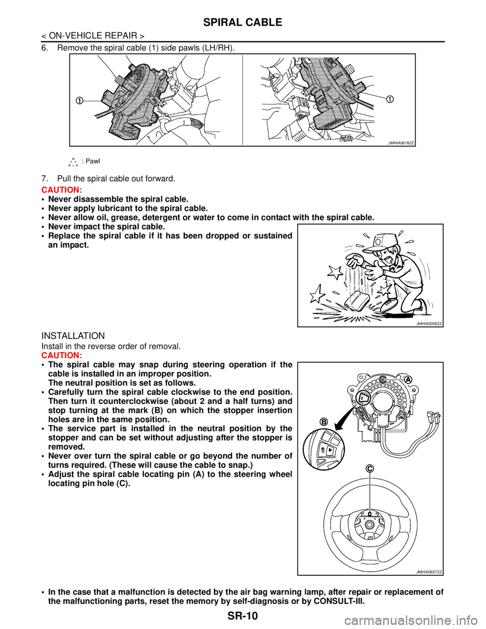
6. Remove the spiral cable (1) side pawls (LH/RH).
7. Pull the spiral cable out forward.
CAUTION:
Never disassemble the spiral cable.
Never apply lubricant to the spiral cable.
Never allow oil, grease, detergent or water to come in contact with the spiral cable.
Never impact the spiral cable.
Replace the spiral cable if it has been dropped or sustained
an impact.
INSTALLATION
Install in the reverse order of removal.
CAUTION:
The spiral cable may snap during steering operation if the
cable is installed in an improper position.
The neutral position is set as follows.
Carefully turn the spiral cable clockwise to the end position.
Then turn it counterclockwise (about 2 and a half turns) and
stop turning at the mark (B) on which the stopper insertion
holes are in the same position.
The service part is installed in the neutral position by the
stopper and can be set without adjusting after the stopper is
removed.
Never over turn the spiral cable or go beyond the number of
turns required. (These will cause the cable to snap.)
Adjust the spiral cable locating pin (A) to the steering wheel
locating pin hole (C).
In the case that a malfunction is detected by the air bag warning lamp, after repair or replacement of
the malfunctioning parts, reset the memory by self-diagnosis or by CONSULT-III.
: Pawl
JMHIA0618ZZ
JMHIA0009ZZ
JMHIA0657ZZ
Page 4242 of 5121
SR-28
< ON-VEHICLE REPAIR >
DISPOSAL OF AIR BAG MODULE AND SEAT BELT PRE-TENSIONER
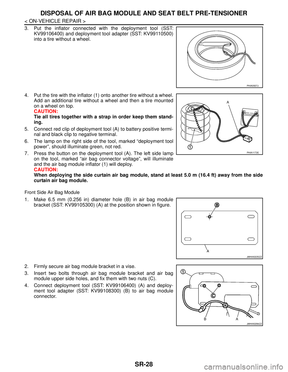
3. Put the inflator connected with the deployment tool (SST:
KV99106400) and deployment tool adapter (SST: KV99110500)
into a tire without a wheel.
4. Put the tire with the inflator (1) onto another tire without a wheel.
Add an additional tire without a wheel and then a tire mounted
on a wheel on top.
CAUTION:
Tie all tires together with a strap in order keep them stand-
ing.
5. Connect red clip of deployment tool (A) to battery positive termi-
nal and black clip to negative terminal.
6. The lamp on the right side of the tool, marked “deployment tool
power”, should illuminate green, not red.
7. Press the button on the deployment tool (A). The left side lamp
on the tool, marked “air bag connector voltage”, will illuminate
and the air bag module inflator (1) will deploy.
CAUTION:
When deploying the side curtain air bag module, stand at least 5.0 m (16.4 ft) away from the side
curtain air bag module.
Front Side Air Bag Module
1. Make 6.5 mm (0.256 in) diameter hole (B) in air bag module
bracket (SST: KV99105300) (A) at the position shown in figure.
2. Firmly secure air bag module bracket in a vise.
3. Insert two bolts through air bag module bracket and air bag
module upper side holes, and fix them with two nuts (C).
4. Connect deployment tool (SST: KV99106400) (A) and deploy-
ment tool adapter (SST: KV99108300) (B) to air bag module
connector.
PHIA0937J
PHIA1173E
JMHIA0225ZZ
JMHIA0284ZZ
Page 4275 of 5121
SRC-32
< COMPONENT DIAGNOSIS >
B1049 DRIVER AIRBAG MODULE
B1049 DRIVER AIRBAG MODULE
DescriptionINFOID:0000000003813957
For driver air bag module, crash is judged by main “G” sensor output signal and safing algorithm in front direc-
tion.
OPERATION
In case of frontal collision whose acceleration exceeds the specified level, the ignition materials are ignited by
electric ignition system. The system burns the gas generating materials resulting in a chemical reaction. This
generates hot gases that flow into the air bag through a filter and expand the bag.
STRUCTURE
Driver air bag module mainly consists of air bag and inflator which inflates air bag.
INSTALLATION
Driver air bag module is installed on the center of steering wheel with fixed bolts.
DTC LogicINFOID:0000000003813958
DTC CONFIRMATION PROCEDURE
1.CHECK SELF-DIAG RESULT
With CONSULT-III
1. Turn ignition switch ON.
2. Perform “AIR BAG” Self Diagnostic Result.
Without CONSULT-III
1. Turn ignition switch ON.
2. Check the air bag warning lamp status. Refer to SRC-10, "
Air Bag Warning Lamp Diagnosis".
NOTE:
SRS does not enter Diagnosis mode if no malfunction is detected in User mode.
Is malfunctioning part detected?
YES >> Refer to SRC-32, "Diagnosis Procedure".
NO >> INSPECTION END
Diagnosis ProcedureINFOID:0000000003813959
WARNING:
With CONSULT-III
Before servicing, turn ignition switch OFF, disconnect battery negative terminal and wait at least 3
minutes. (To discharge backup capacitor.)
Never use unspecified tester or other measuring device.
1.CHECK HARNESS CONNECTOR
Check the harness connector.
Is the inspection result normal?
YES >> GO TO 2.
NO >> Replace harness connector.
2.CHECK WIRING HARNESS
Check the wiring harness externals.
Is the inspection result normal?
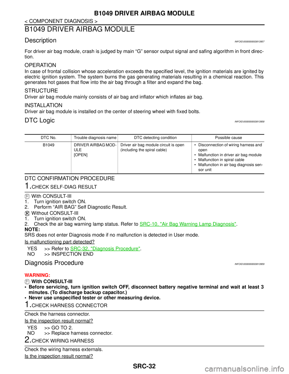
DTC No. Trouble diagnosis name DTC detecting condition Possible cause
B1049 DRIVER AIRBAG MOD-
ULE
[OPEN]Driver air bag module circuit is open
(including the spiral cable) Disconnection of wiring harness and
open
Malfunction in driver air bag module
Malfunction in spiral cable
Malfunction in air bag diagnosis sen-
sor unit
Page 4277 of 5121
SRC-34
< COMPONENT DIAGNOSIS >
B1050 DRIVER AIRBAG MODULE
B1050 DRIVER AIRBAG MODULE
DescriptionINFOID:0000000003813960
For driver air bag module, crash is judged by main “G” sensor output signal and safing algorithm in front direc-
tion.
OPERATION
In case of frontal collision whose acceleration exceeds the specified level, the ignition materials are ignited by
electric ignition system. The system burns the gas generating materials resulting in a chemical reaction. This
generates hot gases that flow into the air bag through a filter and expand the bag.
STRUCTURE
Driver air bag module mainly consists of air bag and inflator which inflates air bag.
INSTALLATION
Driver air bag module is installed on the center of steering wheel with fixed bolts.
DTC LogicINFOID:0000000003813961
DTC CONFIRMATION PROCEDURE
1.CHECK SELF-DIAG RESULT
With CONSULT-III
1. Turn ignition switch ON.
2. Perform “AIR BAG” Self Diagnostic Result.
Without CONSULT-III
1. Turn ignition switch ON.
2. Check the air bag warning lamp status. Refer to SRC-10, "
Air Bag Warning Lamp Diagnosis".
NOTE:
SRS does not enter Diagnosis mode if no malfunction is detected in User mode.
Is malfunctioning part detected?
YES >> Refer to SRC-34, "Diagnosis Procedure".
NO >> INSPECTION END
Diagnosis ProcedureINFOID:0000000003813962
WARNING:
Before servicing, turn ignition switch OFF, disconnect battery negative terminal and wait at least 3
minutes. (To discharge backup capacitor.)
Never use unspecified tester or other measuring device.
1.CHECK HARNESS CONNECTOR
Check the harness connector.
Is the inspection result normal?
YES >> GO TO 2.
NO >> Replace harness connector.
2.CHECK WIRING HARNESS
Check the wiring harness externals.
Is the inspection result normal?
YES >> GO TO 3.
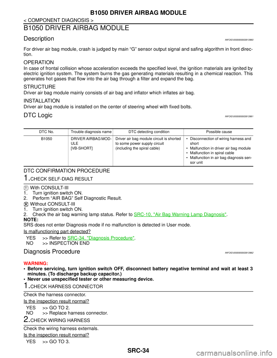
DTC No. Trouble diagnosis name DTC detecting condition Possible cause
B1050 DRIVER AIRBAG MOD-
ULE
[VB-SHORT]Driver air bag module circuit is shorted
to some power supply circuit
(including the spiral cable) Disconnection of wiring harness and
short
Malfunction in driver air bag module
Malfunction in spiral cable
Malfunction in air bag diagnosis sen-
sor unit