2008 NISSAN TEANA wheel
[x] Cancel search: wheelPage 4279 of 5121
SRC-36
< COMPONENT DIAGNOSIS >
B1051 DRIVER AIRBAG MODULE
B1051 DRIVER AIRBAG MODULE
DescriptionINFOID:0000000003813963
For driver air bag module, crash is judged by main “G” sensor output signal and safing algorithm in front direc-
tion.
OPERATION
In case of frontal collision whose acceleration exceeds the specified level, the ignition materials are ignited by
electric ignition system. The system burns the gas generating materials resulting in a chemical reaction. This
generates hot gases that flow into the air bag through a filter and expand the bag.
STRUCTURE
Driver air bag module mainly consists of air bag and inflator which inflates air bag.
INSTALLATION
Driver air bag module is installed on the center of steering wheel with fixed bolts.
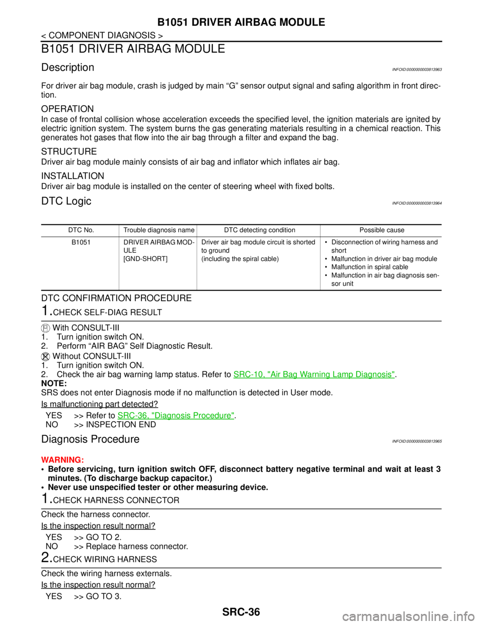
DTC LogicINFOID:0000000003813964
DTC CONFIRMATION PROCEDURE
1.CHECK SELF-DIAG RESULT
With CONSULT-III
1. Turn ignition switch ON.
2. Perform “AIR BAG” Self Diagnostic Result.
Without CONSULT-III
1. Turn ignition switch ON.
2. Check the air bag warning lamp status. Refer to SRC-10, "
Air Bag Warning Lamp Diagnosis".
NOTE:
SRS does not enter Diagnosis mode if no malfunction is detected in User mode.
Is malfunctioning part detected?
YES >> Refer to SRC-36, "Diagnosis Procedure".
NO >> INSPECTION END
Diagnosis ProcedureINFOID:0000000003813965
WARNING:
Before servicing, turn ignition switch OFF, disconnect battery negative terminal and wait at least 3
minutes. (To discharge backup capacitor.)
Never use unspecified tester or other measuring device.
1.CHECK HARNESS CONNECTOR
Check the harness connector.
Is the inspection result normal?
YES >> GO TO 2.
NO >> Replace harness connector.
2.CHECK WIRING HARNESS
Check the wiring harness externals.
Is the inspection result normal?
YES >> GO TO 3.
DTC No. Trouble diagnosis name DTC detecting condition Possible cause
B1051 DRIVER AIRBAG MOD-
ULE
[GND-SHORT]Driver air bag module circuit is shorted
to ground
(including the spiral cable) Disconnection of wiring harness and
short
Malfunction in driver air bag module
Malfunction in spiral cable
Malfunction in air bag diagnosis sen-
sor unit
Page 4281 of 5121

SRC-38
< COMPONENT DIAGNOSIS >
B1052 DRIVER AIRBAG MODULE
B1052 DRIVER AIRBAG MODULE
DescriptionINFOID:0000000003813966
For driver air bag module, crash is judged by main “G” sensor output signal and safing algorithm in front direc-
tion.
OPERATION
In case of frontal collision whose acceleration exceeds the specified level, the ignition materials are ignited by
electric ignition system. The system burns the gas generating materials resulting in a chemical reaction. This
generates hot gases that flow into the air bag through a filter and expand the bag.
STRUCTURE
Driver air bag module mainly consists of air bag and inflator which inflates air bag.
INSTALLATION
Driver air bag module is installed on the center of steering wheel with fixed bolts.
DTC LogicINFOID:0000000003813967
DTC CONFIRMATION PROCEDURE
1.CHECK SELF-DIAG RESULT
With CONSULT-III
1. Turn ignition switch ON.
2. Perform “AIR BAG” Self Diagnostic Result.
Without CONSULT-III
1. Turn ignition switch ON.
2. Check the air bag warning lamp status. Refer to SRC-10, "
Air Bag Warning Lamp Diagnosis".
NOTE:
SRS does not enter Diagnosis mode if no malfunction is detected in User mode.
Is malfunctioning part detected?
YES >> Refer to SRC-38, "Diagnosis Procedure".
NO >> INSPECTION END
Diagnosis ProcedureINFOID:0000000003813968
WARNING:
Before servicing, turn ignition switch OFF, disconnect battery negative terminal and wait at least 3
minutes. (To discharge backup capacitor.)
Never use unspecified tester or other measuring device.
1.CHECK HARNESS CONNECTOR
Check the harness connector.
Is the inspection result normal?
YES >> GO TO 2.
NO >> Replace harness connector.
2.CHECK WIRING HARNESS
Check the wiring harness externals.
Is the inspection result normal?
YES >> GO TO 3.
DTC No. Trouble diagnosis name DTC detecting condition Possible cause
B1052 DRIVER AIRBAG MOD-
ULE
[SHORT]Driver air bag module circuit are shorted
to each other
(including the spiral cable) Disconnection of wiring harness
and short
Malfunction in driver air bag module
Malfunction in spiral cable
Malfunction in air bag diagnosis sen-
sor unit
Page 4366 of 5121
B1209 FRONTAL COLLISION DETECTION
SRC-123
< COMPONENT DIAGNOSIS >
C
D
E
F
G
I
J
K
L
MA
B
SRC
N
O
P
YES >> Replace front seat belt pre-tensioner. Refer to SB-5, "SEAT BELT RETRACTOR : Exploded
View".
NO >> GO TO 3.
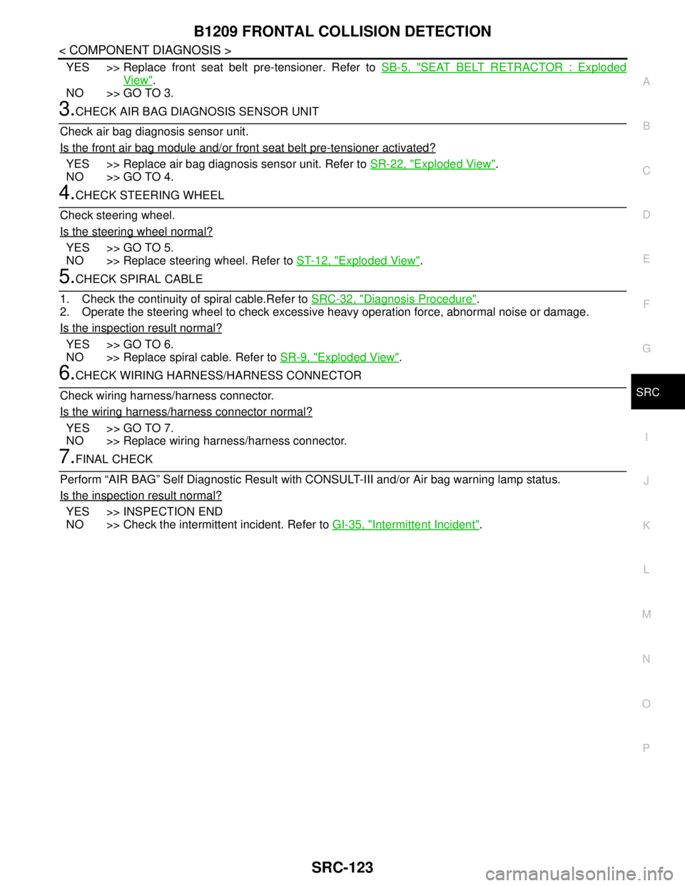
3.CHECK AIR BAG DIAGNOSIS SENSOR UNIT
Check air bag diagnosis sensor unit.
Is the front air bag module and/or front seat belt pre-tensioner activated?
YES >> Replace air bag diagnosis sensor unit. Refer to SR-22, "Exploded View".
NO >> GO TO 4.
4.CHECK STEERING WHEEL
Check steering wheel.
Is the steering wheel normal?
YES >> GO TO 5.
NO >> Replace steering wheel. Refer to ST-12, "
Exploded View".
5.CHECK SPIRAL CABLE
1. Check the continuity of spiral cable.Refer to SRC-32, "
Diagnosis Procedure".
2. Operate the steering wheel to check excessive heavy operation force, abnormal noise or damage.
Is the inspection result normal?
YES >> GO TO 6.
NO >> Replace spiral cable. Refer to SR-9, "
Exploded View".
6.CHECK WIRING HARNESS/HARNESS CONNECTOR
Check wiring harness/harness connector.
Is the wiring harness/harness connector normal?
YES >> GO TO 7.
NO >> Replace wiring harness/harness connector.
7.FINAL CHECK
Perform “AIR BAG” Self Diagnostic Result with CONSULT-III and/or Air bag warning lamp status.
Is the inspection result normal?
YES >> INSPECTION END
NO >> Check the intermittent incident. Refer to GI-35, "
Intermittent Incident".
Page 4390 of 5121
PRECAUTIONS
SRC-147
< PRECAUTION >
C
D
E
F
G
I
J
K
L
MA
B
SRC
N
O
P
PRECAUTION
PRECAUTIONS
Precaution for Supplemental Restraint System (SRS) "AIR BAG" and "SEAT BELT
PRE-TENSIONER"
INFOID:0000000003814141
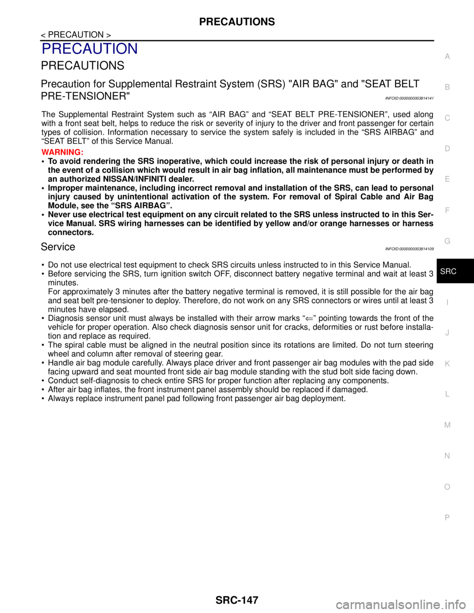
The Supplemental Restraint System such as “AIR BAG” and “SEAT BELT PRE-TENSIONER”, used along
with a front seat belt, helps to reduce the risk or severity of injury to the driver and front passenger for certain
types of collision. Information necessary to service the system safely is included in the “SRS AIRBAG” and
“SEAT BELT” of this Service Manual.
WARNING:
To avoid rendering the SRS inoperative, which could increase the risk of personal injury or death in
the event of a collision which would result in air bag inflation, all maintenance must be performed by
an authorized NISSAN/INFINITI dealer.
Improper maintenance, including incorrect removal and installation of the SRS, can lead to personal
injury caused by unintentional activation of the system. For removal of Spiral Cable and Air Bag
Module, see the “SRS AIRBAG”.
Never use electrical test equipment on any circuit related to the SRS unless instructed to in this Ser-
vice Manual. SRS wiring harnesses can be identified by yellow and/or orange harnesses or harness
connectors.
ServiceINFOID:0000000003814109
Do not use electrical test equipment to check SRS circuits unless instructed to in this Service Manual.
Before servicing the SRS, turn ignition switch OFF, disconnect battery negative terminal and wait at least 3
minutes.
For approximately 3 minutes after the battery negative terminal is removed, it is still possible for the air bag
and seat belt pre-tensioner to deploy. Therefore, do not work on any SRS connectors or wires until at least 3
minutes have elapsed.
Diagnosis sensor unit must always be installed with their arrow marks “⇐” pointing towards the front of the
vehicle for proper operation. Also check diagnosis sensor unit for cracks, deformities or rust before installa-
tion and replace as required.
The spiral cable must be aligned in the neutral position since its rotations are limited. Do not turn steering
wheel and column after removal of steering gear.
Handle air bag module carefully. Always place driver and front passenger air bag modules with the pad side
facing upward and seat mounted front side air bag module standing with the stud bolt side facing down.
Conduct self-diagnosis to check entire SRS for proper function after replacing any components.
After air bag inflates, the front instrument panel assembly should be replaced if damaged.
Always replace instrument panel pad following front passenger air bag deployment.
Page 4391 of 5121

ST-1
STEERING
C
DE
F
H I
J
K L
M
SECTION ST
A
B
ST
N
O P
CONTENTS
STEERING SYSTEM
SYMPTOM DIAGNOSIS ..... ..........................2
NOISE, VIBRATION AND HARSHNESS
(NVH) TROUBLESHOOTING ........................ .....
2
NVH Troubleshooting Chart ................................ ......2
PRECAUTION ...............................................3
PRECAUTIONS .............................................. .....3
Precaution for Supplemental Restraint System
(SRS) "AIR BAG" and "SEAT BELT PRE-TEN-
SIONER" ............................................................. ......
3
Precaution Necessary for Steering Wheel Rota-
tion after Battery Disconnect .....................................
3
Service Notice or Precautions for Steering System
......
3
PREPARATION ............................................5
PREPARATION .............................................. .....5
Special Service Tools .......................................... ......5
ON-VEHICLE MAINTENANCE .....................7
POWER STEERING FLUID ........................... .....7
Inspection ............................................................ ......7
STEERING WHEEL .............................................9
Inspection ............................................................ ......9
ON-VEHICLE REPAIR .................................12
STEERING WHEEL ........................................ ....12
Exploded View .................................................... ....12
Removal and Installation .........................................12
STEERING COLUMN .........................................13
Exploded View .................................................... ....13
Removal and Installation .........................................13
Inspection ................................................................14
LOWER SHAFT ................................................16
Exploded View ..................................................... ....16
Removal and Installation .........................................16
Inspection ................................................................17
STEERING GEAR AND LINKAGE ...................18
Exploded View .........................................................18
Removal and Installation .........................................19
Disassembly and Assembly .....................................20
Inspection ................................................................26
POWER STEERING OIL PUMP .......................28
Exploded View .........................................................28
Removal and Installation .........................................29
Disassembly and Assembly .....................................29
Inspection ................................................................32
HYDRAULIC LINE ............................................34
Exploded View .........................................................34
Removal and Installation .........................................35
SERVICE DATA AND SPECIFICATIONS
(SDS) ............... .............................................
37
SERVICE DATA AND SPECIFICATIONS
(SDS) .................................................................
37
General Specifications ......................................... ....37
Steering Wheel Axial End Play and Play .................37
Steering Wheel Turning Force .................................37
Steering Angle .........................................................37
Steering Column Length ..........................................37
Steering Column Mounting Dimensions ..................37
Steering Column Operating Range .........................37
Lower Shaft Sliding Range ......................................38
Rack Sliding Force ..................................................38
Rack Stroke .............................................................38
Socket Swing Force and Rotating Torque ...............38
Socket Axial End Play .............................................38
Inner Socket Length ................................................38
Relief Oil Pressure ...................................................38
Page 4392 of 5121
ST-2
< SYMPTOM DIAGNOSIS >
NOISE, VIBRATION AND HARSHNESS (NVH) TROUBLESHOOTING
SYMPTOM DIAGNOSIS
NOISE, VIBRATION AND HARSHNESS (NVH) TROUBLESHOOTING
NVH Troubleshooting ChartINFOID:0000000003806305
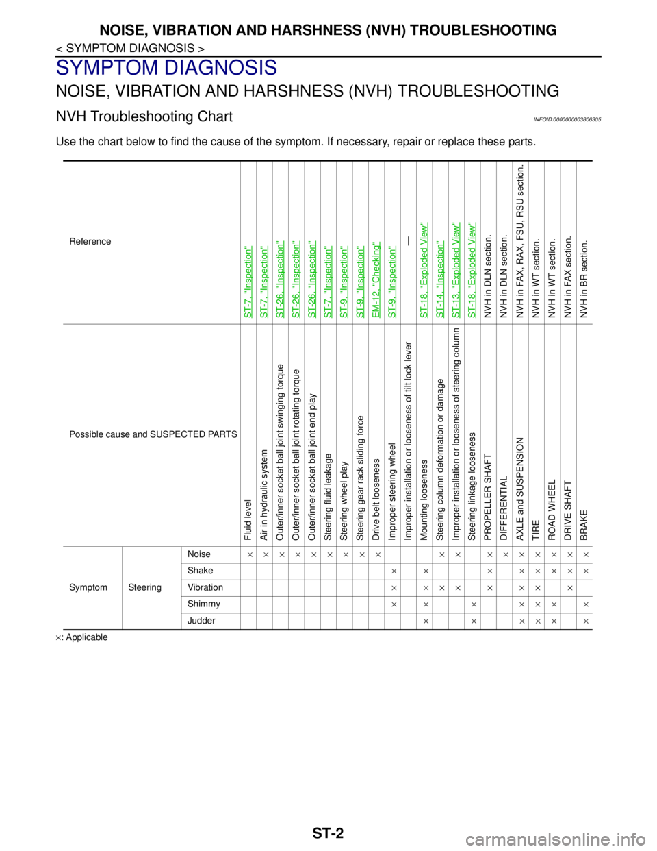
Use the chart below to find the cause of the symptom. If necessary, repair or replace these parts.
×: ApplicableReference
ST-7, "
Inspection
"
ST-7, "
Inspection
"
ST-26, "
Inspection
"
ST-26, "
Inspection
"
ST-26, "
Inspection
"
ST-7, "
Inspection
"
ST-9, "
Inspection
"
ST-9, "
Inspection
"
EM-12, "
Checking
"
ST-9, "
Inspection
"—
ST-18, "
Exploded View
"
ST-14, "
Inspection
"
ST-13, "
Exploded View
"
ST-18, "
Exploded View
"
NVH in DLN section.
NVH in DLN section.
NVH in FAX, RAX, FSU, RSU section.
NVH in WT section.
NVH in WT section.
NVH in FAX section.
NVH in BR section.
Possible cause and SUSPECTED PARTS
Fluid level
Air in hydraulic system
Outer/inner socket ball joint swinging torque
Outer/inner socket ball joint rotating torque
Outer/inner socket ball joint end play
Steering fluid leakage
Steering wheel play
Steering gear rack sliding force
Drive belt looseness
Improper steering wheel
Improper installation or looseness of tilt lock lever
Mounting looseness
Steering column deformation or damage
Improper installation or looseness of steering column
Steering linkage looseness
PROPELLER SHAFT
DIFFERENTIAL
AXLE and SUSPENSION
TIRE
ROAD WHEEL
DRIVE SHAFT
BRAKE
Symptom SteeringNoise××××××××× ×× ×××××××
Shake× × × ×××××
Vibration××××××××
Shimmy×× × ××××
Judder××××××
Page 4393 of 5121
PRECAUTIONS
ST-3
< PRECAUTION >
C
D
E
F
H
I
J
K
L
MA
B
ST
N
O
P
PRECAUTION
PRECAUTIONS
Precaution for Supplemental Restraint System (SRS) "AIR BAG" and "SEAT BELT
PRE-TENSIONER"
INFOID:0000000003971958
The Supplemental Restraint System such as “AIR BAG” and “SEAT BELT PRE-TENSIONER”, used along
with a front seat belt, helps to reduce the risk or severity of injury to the driver and front passenger for certain
types of collision. Information necessary to service the system safely is included in the “SRS AIRBAG” and
“SEAT BELT” of this Service Manual.
WARNING:
• To avoid rendering the SRS inoperative, which could increase the risk of personal injury or death in
the event of a collision which would result in air bag inflation, all maintenance must be performed by
an authorized NISSAN/INFINITI dealer.
Improper maintenance, including incorrect removal and installation of the SRS, can lead to personal
injury caused by unintentional activation of the system. For removal of Spiral Cable and Air Bag
Module, see the “SRS AIRBAG”.
Never use electrical test equipment on any circuit related to the SRS unless instructed to in this Ser-
vice Manual. SRS wiring harnesses can be identified by yellow and/or orange harnesses or harness
connectors.
Precaution Necessary for Steering Wheel Rotation after Battery Disconnect
INFOID:0000000003806307
NOTE:
Before removing and installing any control units, first turn the push-button ignition switch to the LOCK posi-
tion, then disconnect both battery cables.
After finishing work, confirm that all control unit connectors are connected properly, then re-connect both
battery cables.
Always use CONSULT-III to perform self-diagnosis as a part of each function inspection after finishing work.
If a DTC is detected, perform trouble diagnosis according to self-diagnosis results.
This vehicle is equipped with a push-button ignition switch and a steering lock unit.
If the battery is disconnected or discharged, the steering wheel will lock and cannot be turned.
If turning the steering wheel is required with the battery disconnected or discharged, follow the procedure
below before starting the repair operation.
OPERATION PROCEDURE
1. Connect both battery cables.
NOTE:
Supply power using jumper cables if battery is discharged.
2. Carry the Intelligent Key or insert it to the key slot and turn the push-button ignition switch to ACC position.
(At this time, the steering lock will be released.)
3. Disconnect both battery cables. The steering lock will remain released with both battery cables discon-
nected and the steering wheel can be turned.
4. Perform the necessary repair operation.
5. When the repair work is completed, re-connect both battery cables. With the brake pedal released, turn
the push-button ignition switch from ACC position to ON position, then to LOCK position. (The steering
wheel will lock when the push-button ignition switch is turned to LOCK position.)
6. Perform self-diagnosis check of all control units using CONSULT-III.
Service Notice or Precautions for Steering SystemINFOID:0000000003806308
CAUTION:
In case of removing steering gear assembly, make the final tightening with grounded and unloaded
vehicle condition, and then check wheel alignment.
Observe the following precautions when disassembling.
- Before disassembly, thoroughly clean the outside of the unit.
- Disassembly should be done in a clean work area. It is important to prevent the internal parts from
becoming contaminated by dirt or other foreign matter.
Page 4395 of 5121
PREPARATION
ST-5
< PREPARATION >
C
D
E
F
H
I
J
K
L
MA
B
ST
N
O
P
PREPARATION
PREPARATION
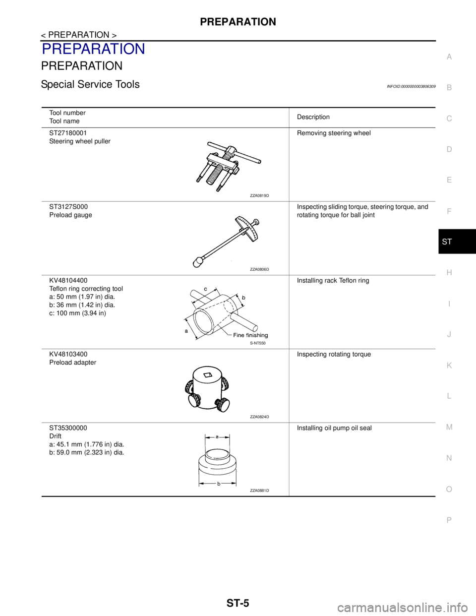
Special Service ToolsINFOID:0000000003806309
Tool number
Tool nameDescription
ST27180001
Steering wheel pullerRemoving steering wheel
ST3127S000
Preload gaugeInspecting sliding torque, steering torque, and
rotating torque for ball joint
KV48104400
Teflon ring correcting tool
a: 50 mm (1.97 in) dia.
b: 36 mm (1.42 in) dia.
c: 100 mm (3.94 in)Installing rack Teflon ring
KV48103400
Preload adapterInspecting rotating torque
ST35300000
Drift
a: 45.1 mm (1.776 in) dia.
b: 59.0 mm (2.323 in) dia.Installing oil pump oil seal
ZZA0819D
ZZA0806D
S-NT550
ZZA0824D
ZZA0881D