2008 NISSAN TEANA wheel
[x] Cancel search: wheelPage 3846 of 5121
RSU-14
< ON-VEHICLE REPAIR >
FRONT LOWER LINK
FRONT LOWER LINK
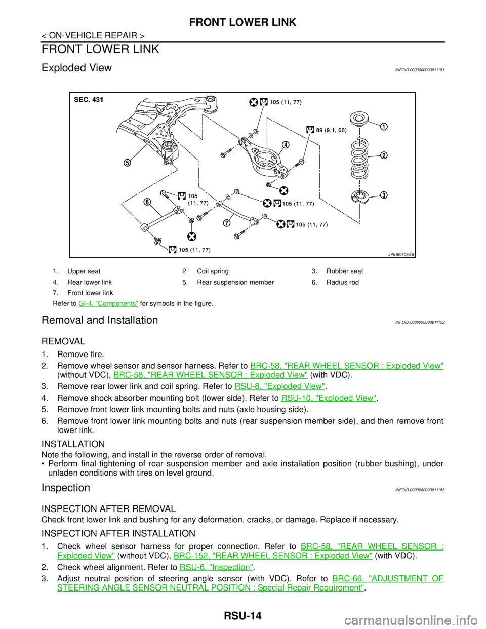
Exploded ViewINFOID:0000000003811151
Removal and InstallationINFOID:0000000003811152
REMOVAL
1. Remove tire.
2. Remove wheel sensor and sensor harness. Refer to BRC-58, "
REAR WHEEL SENSOR : Exploded View"
(without VDC), BRC-58, "REAR WHEEL SENSOR : Exploded View" (with VDC).
3. Remove rear lower link and coil spring. Refer to RSU-8, "
Exploded View".
4. Remove shock absorber mounting bolt (lower side). Refer to RSU-10, "
Exploded View".
5. Remove front lower link mounting bolts and nuts (axle housing side).
6. Remove front lower link mounting bolts and nuts (rear suspension member side), and then remove front
lower link.
INSTALLATION
Note the following, and install in the reverse order of removal.
Perform final tightening of rear suspension member and axle installation position (rubber bushing), under
unladen conditions with tires on level ground.
InspectionINFOID:0000000003811153
INSPECTION AFTER REMOVAL
Check front lower link and bushing for any deformation, cracks, or damage. Replace if necessary.
INSPECTION AFTER INSTALLATION
1. Check wheel sensor harness for proper connection. Refer to BRC-58, "REAR WHEEL SENSOR :
Exploded View" (without VDC), BRC-152, "REAR WHEEL SENSOR : Exploded View" (with VDC).
2. Check wheel alignment. Refer to RSU-6, "
Inspection".
3. Adjust neutral position of steering angle sensor (with VDC). Refer to BRC-66, "
ADJUSTMENT OF
STEERING ANGLE SENSOR NEUTRAL POSITION : Special Repair Requirement".
1. Upper seat 2. Coil spring 3. Rubber seat
4. Rear lower link 5. Rear suspension member 6. Radius rod
7. Front lower link
Refer to GI-4, "
Components" for symbols in the figure.
JPEIB0108GB
Page 3849 of 5121
REAR SUSPENSION ARM
RSU-17
< REMOVAL AND INSTALLATION >
C
D
F
G
H
I
J
K
L
MA
B
RSU
N
O
P
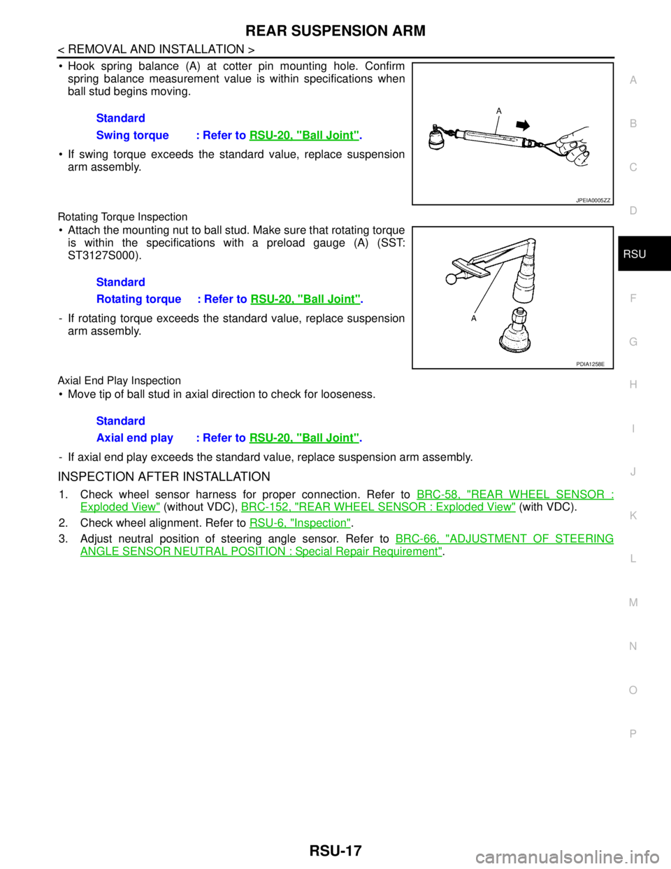
Hook spring balance (A) at cotter pin mounting hole. Confirm
spring balance measurement value is within specifications when
ball stud begins moving.
If swing torque exceeds the standard value, replace suspension
arm assembly.
Rotating Torque Inspection
Attach the mounting nut to ball stud. Make sure that rotating torque
is within the specifications with a preload gauge (A) (SST:
ST3127S000).
- If rotating torque exceeds the standard value, replace suspension
arm assembly.
Axial End Play Inspection
Move tip of ball stud in axial direction to check for looseness.
- If axial end play exceeds the standard value, replace suspension arm assembly.
INSPECTION AFTER INSTALLATION
1. Check wheel sensor harness for proper connection. Refer to BRC-58, "REAR WHEEL SENSOR :
Exploded View" (without VDC), BRC-152, "REAR WHEEL SENSOR : Exploded View" (with VDC).
2. Check wheel alignment. Refer to RSU-6, "
Inspection".
3. Adjust neutral position of steering angle sensor. Refer to BRC-66, "
ADJUSTMENT OF STEERING
ANGLE SENSOR NEUTRAL POSITION : Special Repair Requirement". Standard
Swing torque : Refer to RSU-20, "
Ball Joint".
JPEIA0005ZZ
Standard
Rotating torque : Refer to RSU-20, "
Ball Joint".
PDIA1258E
Standard
Axial end play : Refer to RSU-20, "
Ball Joint".
Page 3850 of 5121
RSU-18
< REMOVAL AND INSTALLATION >
REAR SUSPENSION MEMBER
REAR SUSPENSION MEMBER
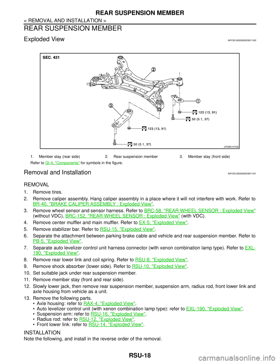
Exploded ViewINFOID:0000000003811160
Removal and InstallationINFOID:0000000003811161
REMOVAL
1. Remove tires.
2. Remove caliper assembly. Hang caliper assembly in a place where it will not interfere with work. Refer to
BR-40, "
BRAKE CALIPER ASSEMBLY : Exploded View".
3. Remove wheel sensor and sensor harness. Refer to BRC-58, "
REAR WHEEL SENSOR : Exploded View"
(without VDC), BRC-152, "REAR WHEEL SENSOR : Exploded View" (with VDC).
4. Remove center muffler and main muffler. Refer to EX-5, "
Exploded View".
5. Remove stabilizer bar. Refer to RSU-15, "
Exploded View".
6. Separate the attachment between parking brake cable and vehicle and rear suspension member. Refer to
PB-5, "
Exploded View".
7. Separate auto levelizer control unit harness connector (with xenon combination lamp type). Refer to EXL-
190, "Exploded View".
8. Remove rear lower link and coil spring. Refer to RSU-8, "
Exploded View".
9. Remove shock absorber (lower side). Refer to RSU-10, "
Exploded View".
10. Set suitable jack under rear suspension member.
11. Remove member stay (front and rear side).
12. Slowly lower jack, then remove rear suspension member, suspension arm, radius rod, front lower link and
axle housing from vehicle as a unit.
13. Remove the following parts.
Axle housing: refer to RAX-4, "
Exploded View".
Auto levelizer control unit (with xenon combination lamp type): refer to EXL-190, "
Exploded View".
Suspension arm: refer to RSU-16, "
Exploded View".
Radius rod: refer to RSU-12, "
Exploded View".
Front lower link: refer to RSU-14, "
Exploded View".
INSTALLATION
Note the following, and install in the reverse order of the removal.
1. Member stay (rear side) 2. Rear suspension member 3. Member stay (front side)
Refer to GI-4, "
Components" for symbols in the figure.
JPEIB0107GB
Page 3851 of 5121
REAR SUSPENSION MEMBER
RSU-19
< REMOVAL AND INSTALLATION >
C
D
F
G
H
I
J
K
L
MA
B
RSU
N
O
P
Perform the final tightening of each of parts under unladen conditions, which were removed when removing
rear suspension assembly.
After final tightening, install auto levelizer control unit (with xenon combination lamp type). Refer to EXL-190,
"Exploded View".
Never reuse cotter pin.
InspectionINFOID:0000000003811162
INSPECTION AFTER REMOVAL
Check rear suspension member for deformation, cracks, or any other damage. Replace if necessary.
INSPECTION AFTER INSTALLATION
1. Check wheel sensor harness for proper connection. Refer to BRC-58, "REAR WHEEL SENSOR :
Exploded View" (without VDC), BRC-152, "REAR WHEEL SENSOR : Exploded View" (with VDC).
2. Adjust parking brake operation (stroke). PB-2, "
Inspection and Adjustment".
3. Check wheel alignment. Refer to RSU-6, "
Inspection".
4. Adjust neutral position of steering angle sensor. Refer to BRC-66, "
ADJUSTMENT OF STEERING
ANGLE SENSOR NEUTRAL POSITION : Special Repair Requirement".
Page 3852 of 5121
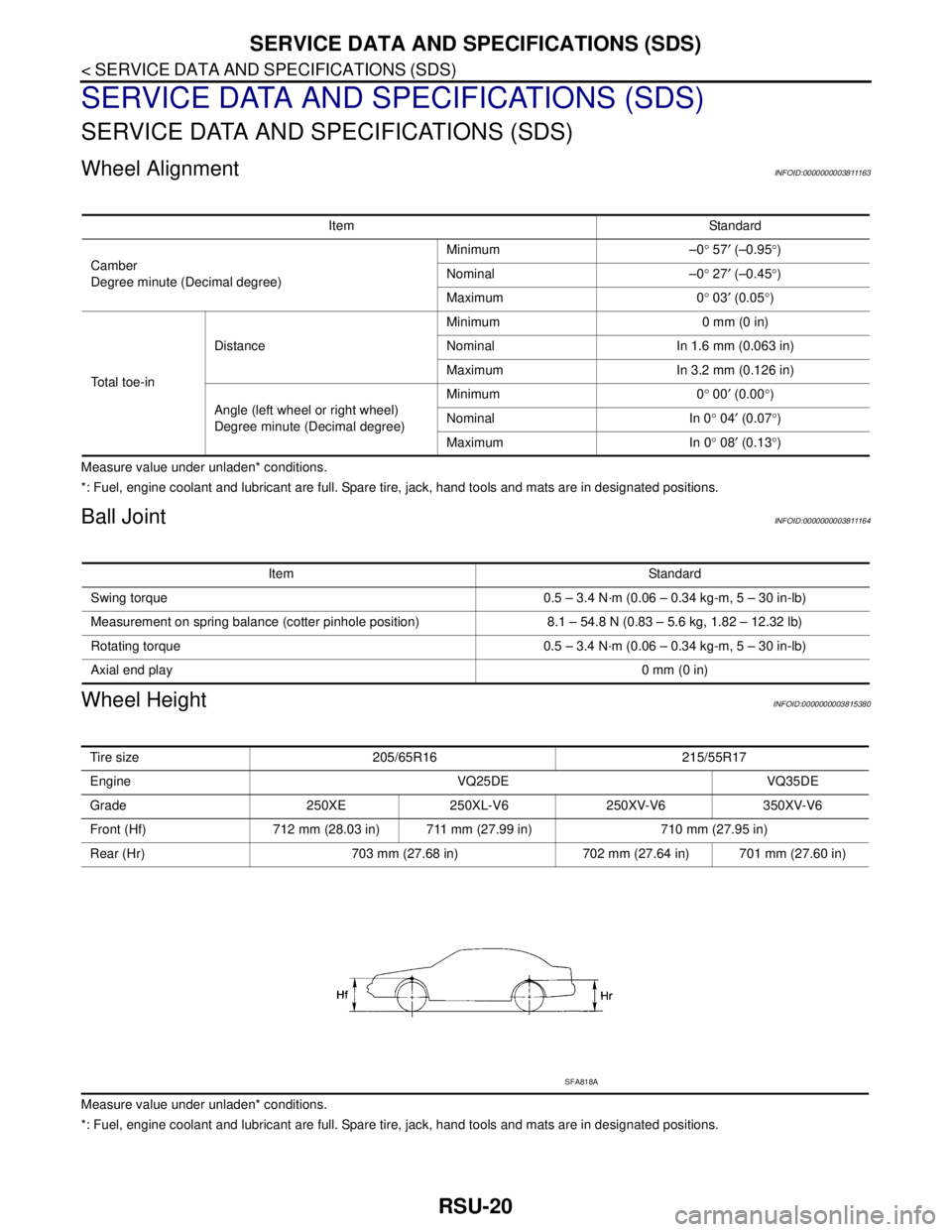
RSU-20
< SERVICE DATA AND SPECIFICATIONS (SDS)
SERVICE DATA AND SPECIFICATIONS (SDS)
SERVICE DATA AND SPECIFICATIONS (SDS)
SERVICE DATA AND SPECIFICATIONS (SDS)
Wheel AlignmentINFOID:0000000003811163
Measure value under unladen* conditions.
*: Fuel, engine coolant and lubricant are full. Spare tire, jack, hand tools and mats are in designated positions.
Ball JointINFOID:0000000003811164
Wheel HeightINFOID:0000000003815380
Measure value under unladen* conditions.
*: Fuel, engine coolant and lubricant are full. Spare tire, jack, hand tools and mats are in designated positions.Item Standard
Camber
Degree minute (Decimal degree)Minimum –0° 57′ (–0.95°)
Nominal –0° 27′ (–0.45°)
Maximum 0° 03′ (0.05°)
To t a l t o e - i nDistanceMinimum 0 mm (0 in)
Nominal In 1.6 mm (0.063 in)
Maximum In 3.2 mm (0.126 in)
Angle (left wheel or right wheel)
Degree minute (Decimal degree)Minimum 0° 00′ (0.00°)
Nominal In 0° 04′ (0.07°)
Maximum In 0° 08′ (0.13°)
Item Standard
Swing torque 0.5 – 3.4 N·m (0.06 – 0.34 kg-m, 5 – 30 in-lb)
Measurement on spring balance (cotter pinhole position) 8.1 – 54.8 N (0.83 – 5.6 kg, 1.82 – 12.32 lb)
Rotating torque 0.5 – 3.4 N·m (0.06 – 0.34 kg-m, 5 – 30 in-lb)
Axial end play0 mm (0 in)
Tire size 205/65R16 215/55R17
Engine VQ25DE VQ35DE
Grade 250XE 250XL-V6 250XV-V6 350XV-V6
Front (Hf) 712 mm (28.03 in) 711 mm (27.99 in) 710 mm (27.95 in)
Rear (Hr) 703 mm (27.68 in) 702 mm (27.64 in) 701 mm (27.60 in)
SFA818A
Page 3867 of 5121

SE-3
C
D
E
F
G
H
I
K
L
MA
B
SE
N
O
P REAR SEAT : Description .......................................
76
REAR SEAT : Diagnosis Procedure .......................76
ONLY SEAT CUSHION HEATER IS OPER-
ATED IN HI MODE OF HEATED SEAT .............
77
FRONT SEAT ............................................................77
FRONT SEAT : Description ....................................77
FRONT SEAT : Diagnosis Procedure .....................77
REAR SEAT ..............................................................77
REAR SEAT : Description .......................................77
REAR SEAT : Diagnosis Procedure .......................77
HEATED SEAT SWITCH INDICATOR DOES
NOT TURN ON ...................................................
78
FRONT SEAT ............................................................78
FRONT SEAT : Diagnosis Procedure .....................78
REAR SEAT ..............................................................78
REAR SEAT : Diagnosis Procedure .......................78
VENTILATION SEAT SWITCH INDICATOR
DOES NOT TURN ON ........................................
79
FRONT SEAT ............................................................79
FRONT SEAT : Diagnosis Procedure .....................79
REAR SEAT ..............................................................79
REAR SEAT : Diagnosis Procedure .......................79
SQUEAK AND RATTLE TROUBLE DIAG-
NOSES ...............................................................
80
Work Flow ...............................................................80
Inspection Procedure ..............................................82
Diagnostic Worksheet .............................................84
PRECAUTION ..............................................86
PRECAUTIONS ..................................................86
Precaution for Supplemental Restraint System
(SRS) "AIR BAG" and "SEAT BELT PRE-TEN-
SIONER" .................................................................
86
Precaution Necessary for Steering Wheel Rota-
tion after Battery Disconnect ...................................
86
Service Notice .........................................................86
Precaution for Work ................................................87
PREPARATION ...........................................88
PREPARATION ..................................................88
Commercial Service Tools .....................................88
ON-VEHICLE REPAIR .................................89
FRONT SEAT .....................................................89
Exploded View ........................................................89
Removal and Installation .........................................92
Disassembly and Assembly ....................................93
REAR SEAT .......................................................98
Exploded View ........................................................98
Removal and Installation .........................................99
Disassembly and Assembly ...................................100
POWER SEAT SWITCH .................................103
Exploded View .......................................................103
Removal and Installation .......................................103
HEATED SEAT SWITCH ................................104
FRONT SEAT ...........................................................104
FRONT SEAT : Exploded View .............................104
FRONT SEAT : Removal and Installation .............104
REAR SEAT .............................................................104
REAR SEAT : Exploded View ...............................105
REAR SEAT : Removal and Installation ................105
VENTILATION SEAT SWITCH .......................106
FRONT SEAT ...........................................................106
FRONT SEAT : Exploded View .............................106
FRONT SEAT : Removal and Installation .............106
REAR SEAT .............................................................106
REAR SEAT : Exploded View ...............................107
REAR SEAT : Removal and Installation ................107
WITHOUT VENTILATION SEAT
FUNCTION DIAGNOSIS ............................
108
POWER SEAT .................................................108
System Description ................................................108
Component Parts Location ....................................108
Component Description .........................................108
HEATED SEAT ...............................................110
System Description ................................................110
Component Parts Location ....................................110
Component Description .........................................110
COMPONENT DIAGNOSIS .......................111
POWER SEAT .................................................111
Wiring Diagram - POWER SEAT FOR DRIVER
SIDE - ....................................................................
111
Wiring Diagram - POWER SEAT FOR PASSEN-
GER SIDE - ...........................................................
114
HEATED SEAT ...............................................118
Wiring Diagram - HEATED SEAT - .......................118
SYMPTOM DIAGNOSIS ............................121
SQUEAK AND RATTLE TROUBLE DIAG-
NOSES ............................................................
121
Work Flow ..............................................................121
Inspection Procedure .............................................123
Diagnostic Worksheet ............................................125
PRECAUTION ............................................127
PRECAUTIONS ...............................................127
Page 3868 of 5121

SE-4
Precaution for Supplemental Restraint System
(SRS) "AIR BAG" and "SEAT BELT PRE-TEN-
SIONER" ................................................................
127
Precaution Necessary for Steering Wheel Rota-
tion after Battery Disconnect .................................
127
Service Notice .......................................................127
Precaution for Work ...............................................128
PREPARATION ..........................................129
PREPARATION ...............................................129
Commercial Service Tools ...................................129
ON-VEHICLE REPAIR ...............................130
FRONT SEAT ..................................................130
Exploded View ......................................................130
Removal and Installation .......................................135
Disassembly and Assembly ..................................135
REAR SEAT .....................................................140
Exploded View ......................................................140
Removal and Installation .......................................142
Disassembly and Assembly ..................................142
POWER SEAT SWITCH ...................................144
Exploded View ......................................................144
Removal and Installation .......................................144
HEATED SEAT SWITCH ..................................145
Exploded View ......................................................145
Removal and Installation .......................................145
Page 3950 of 5121
![NISSAN TEANA 2008 Service Manual SE-86
< PRECAUTION >[WITH VENTILATION SEAT]
PRECAUTIONS
PRECAUTION
PRECAUTIONS
Precaution for Supplemental Restraint System (SRS) "AIR BAG" and "SEAT BELT
PRE-TENSIONER"
INFOID:0000000003940149
The S NISSAN TEANA 2008 Service Manual SE-86
< PRECAUTION >[WITH VENTILATION SEAT]
PRECAUTIONS
PRECAUTION
PRECAUTIONS
Precaution for Supplemental Restraint System (SRS) "AIR BAG" and "SEAT BELT
PRE-TENSIONER"
INFOID:0000000003940149
The S](/manual-img/5/57391/w960_57391-3949.png)
SE-86
< PRECAUTION >[WITH VENTILATION SEAT]
PRECAUTIONS
PRECAUTION
PRECAUTIONS
Precaution for Supplemental Restraint System (SRS) "AIR BAG" and "SEAT BELT
PRE-TENSIONER"
INFOID:0000000003940149
The Supplemental Restraint System such as “AIR BAG” and “SEAT BELT PRE-TENSIONER”, used along
with a front seat belt, helps to reduce the risk or severity of injury to the driver and front passenger for certain
types of collision. Information necessary to service the system safely is included in the “SRS AIRBAG” and
“SEAT BELT” of this Service Manual.
WARNING:
• To avoid rendering the SRS inoperative, which could increase the risk of personal injury or death in
the event of a collision which would result in air bag inflation, all maintenance must be performed by
an authorized NISSAN/INFINITI dealer.
Improper maintenance, including incorrect removal and installation of the SRS, can lead to personal
injury caused by unintentional activation of the system. For removal of Spiral Cable and Air Bag
Module, see the “SRS AIRBAG”.
Never use electrical test equipment on any circuit related to the SRS unless instructed to in this Ser-
vice Manual. SRS wiring harnesses can be identified by yellow and/or orange harnesses or harness
connectors.
Precaution Necessary for Steering Wheel Rotation after Battery Disconnect
INFOID:0000000003885169
NOTE:
Before removing and installing any control units, first turn the push-button ignition switch to the LOCK posi-
tion, then disconnect both battery cables.
After finishing work, confirm that all control unit connectors are connected properly, then re-connect both
battery cables.
Always use CONSULT-III to perform self-diagnosis as a part of each function inspection after finishing work.
If a DTC is detected, perform trouble diagnosis according to self-diagnosis results.
This vehicle is equipped with a push-button ignition switch and a steering lock unit.
If the battery is disconnected or discharged, the steering wheel will lock and cannot be turned.
If turning the steering wheel is required with the battery disconnected or discharged, follow the procedure
below before starting the repair operation.
OPERATION PROCEDURE
1. Connect both battery cables.
NOTE:
Supply power using jumper cables if battery is discharged.
2. Turn the push-button ignition switch to ACC position.
(At this time, the steering lock will be released.)
3. Disconnect both battery cables. The steering lock will remain released with both battery cables discon-
nected and the steering wheel can be turned.
4. Perform the necessary repair operation.
5. When the repair work is completed, re-connect both battery cables. With the brake pedal released, turn
the push-button ignition switch from ACC position to ON position, then to LOCK position. (The steering
wheel will lock when the push-button ignition switch is turned to LOCK position.)
6. Perform self-diagnosis check of all control units using CONSULT-III.
Service NoticeINFOID:0000000003809271
When removing or installing various parts, place a cloth or padding onto the vehicle body to prevent
scratches.
Handle trim, molding, instruments, grille, etc. carefully during removing or installing. Be careful not to oil or
damage them.
Apply sealing compound where necessary when installing parts.
When applying sealing compound, be careful that the sealing compound does not protrude from parts.