Page 3726 of 5121
RAX-1
TRANSMISSION & DRIVELINE
CEF
G H
I
J
K L
M
SECTION RAX
A
B
RAX
N
O P
CONTENTS
REAR AXLE
SYMPTOM DIAGNOSIS ..... ..........................2
NOISE, VIBRATION AND HARSHNESS
(NVH) TROUBLESHOOTING ........................ .....
2
NVH Troubleshooting Chart ................................ ......2
ON-VEHICLE MAINTENANCE .....................3
REAR WHEEL HUB AND HOUSING ............ .....3
Inspection ............................................................ ......3
ON-VEHICLE REPAIR ..................................4
REAR WHEEL HUB AND HOUSING ................4
Exploded View ..................................................... .....4
Removal and Installation ..........................................4
Inspection .................................................................5
SERVICE DATA AND SPECIFICATIONS
(SDS) ............... ..............................................
6
SERVICE DATA AND SPECIFICATIONS
(SDS) ..................................................................
6
Wheel Bearing ..................................................... .....6
Page 3727 of 5121
RAX-2
< SYMPTOM DIAGNOSIS >
NOISE, VIBRATION AND HARSHNESS (NVH) TROUBLESHOOTING
SYMPTOM DIAGNOSIS
NOISE, VIBRATION AND HARSHNESS (NVH) TROUBLESHOOTING
NVH Troubleshooting ChartINFOID:0000000003811096
Use chart below to find the cause of the symptom. If necessary, repair or replace these parts.
×: ApplicableReference page
RAX-4—
RAX-3
NVH in RAX and RSU sections
NVH in WT section
NVH in WT section
NVH in BR section
Possible cause and SUSPECTED PARTS
Improper installation, looseness
Parts interference
Wheel bearing damage
REAR AXLE AND REAR SUSPENSION
TIRE
ROAD WHEEL
BRAKE
Symptom REAR AXLENoise×××××××
Shake×××××××
Vibration×××××
Shimmy×× ××××
Judder×××××
Poor quality ride or handling×× ×××
Page 3728 of 5121
REAR WHEEL HUB AND HOUSING
RAX-3
< ON-VEHICLE MAINTENANCE >
C
E
F
G
H
I
J
K
L
MA
B
RAX
N
O
P
ON-VEHICLE MAINTENANCE
REAR WHEEL HUB AND HOUSING
InspectionINFOID:0000000003811098
MOUNTING INSPECTION
Make sure the mounting conditions (looseness, back lash) of each component and component conditions
(wear, damage) are normal.
WHEEL BEARING INSPECTION
Move wheel hub and bearing assembly in the axial direction by hand. Make sure there is no looseness of
wheel bearing.
Rotate wheel hub, and make sure there is no unusual noise or other irregular conditions. If there is any of
irregular conditions, replace wheel hub and bearing assembly.Standard
Axial end play : Refer to RAX-6, "
Wheel Bearing".
Page 3729 of 5121
RAX-4
< ON-VEHICLE REPAIR >
REAR WHEEL HUB AND HOUSING
ON-VEHICLE REPAIR
REAR WHEEL HUB AND HOUSING
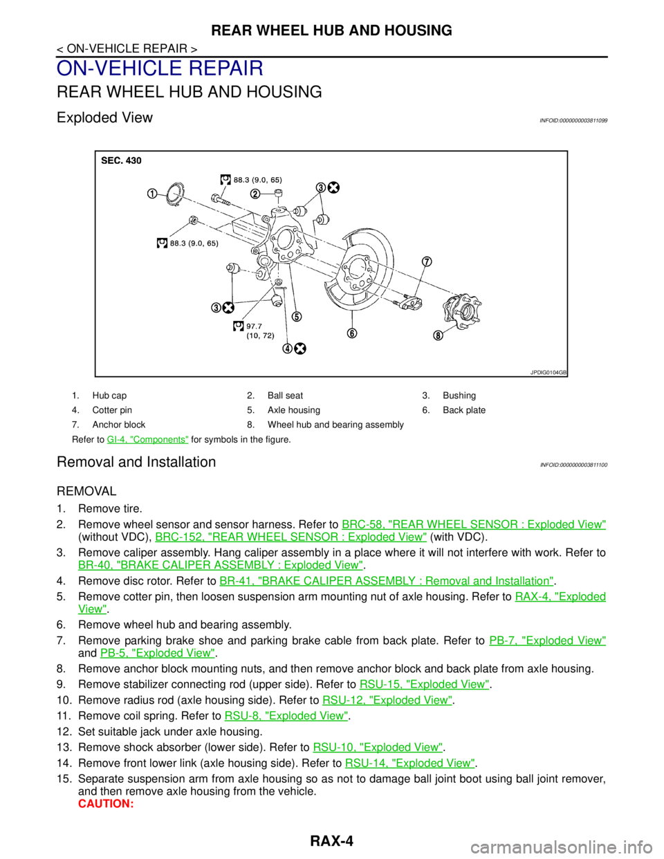
Exploded ViewINFOID:0000000003811099
Removal and InstallationINFOID:0000000003811100
REMOVAL
1. Remove tire.
2. Remove wheel sensor and sensor harness. Refer to BRC-58, "
REAR WHEEL SENSOR : Exploded View"
(without VDC), BRC-152, "REAR WHEEL SENSOR : Exploded View" (with VDC).
3. Remove caliper assembly. Hang caliper assembly in a place where it will not interfere with work. Refer to
BR-40, "
BRAKE CALIPER ASSEMBLY : Exploded View".
4. Remove disc rotor. Refer to BR-41, "
BRAKE CALIPER ASSEMBLY : Removal and Installation".
5. Remove cotter pin, then loosen suspension arm mounting nut of axle housing. Refer to RAX-4, "
Exploded
View".
6. Remove wheel hub and bearing assembly.
7. Remove parking brake shoe and parking brake cable from back plate. Refer to PB-7, "
Exploded View"
and PB-5, "Exploded View".
8. Remove anchor block mounting nuts, and then remove anchor block and back plate from axle housing.
9. Remove stabilizer connecting rod (upper side). Refer to RSU-15, "
Exploded View".
10. Remove radius rod (axle housing side). Refer to RSU-12, "
Exploded View".
11. Remove coil spring. Refer to RSU-8, "
Exploded View".
12. Set suitable jack under axle housing.
13. Remove shock absorber (lower side). Refer to RSU-10, "
Exploded View".
14. Remove front lower link (axle housing side). Refer to RSU-14, "
Exploded View".
15. Separate suspension arm from axle housing so as not to damage ball joint boot using ball joint remover,
and then remove axle housing from the vehicle.
CAUTION:
1. Hub cap 2. Ball seat 3. Bushing
4. Cotter pin 5. Axle housing 6. Back plate
7. Anchor block 8. Wheel hub and bearing assembly
Refer to GI-4, "
Components" for symbols in the figure.
JPDIG0104GB
Page 3730 of 5121
REAR WHEEL HUB AND HOUSING
RAX-5
< ON-VEHICLE REPAIR >
C
E
F
G
H
I
J
K
L
MA
B
RAX
N
O
P
Temporarily tighten nuts to prevent damage to threads and to prevent the ball joint remover from
coming off.
16. Remove hub cap.
INSTALLATION
Note the following, and install in the reverse order of removal.
Perform the final tightening of each of parts under unladen conditions, which were removed when removing
wheel hub and bearing assembly and steering knuckle.
Never reuse cotter pin.
InspectionINFOID:0000000003811101
INSPECTION AFTER REMOVAL
Wheel Hub and Bearing Assembly
Check the wheel hub and bearing assembly for wear, cracks, and damage. Replace if necessary.
Axle Housing
Check the axle housing for wear, cracks, and damage. Replace if necessary.
Ball Joint Inspection
Check for boot breakage, axial looseness, and torque of suspension arm ball joint. Refer to RSU-16, "Inspec-
tion".
INSPECTION AFTER INSTALLATION
1. Check wheel sensor harness for proper connection. Refer to BRC-58, "REAR WHEEL SENSOR :
Exploded View" (without VDC), BRC-152, "REAR WHEEL SENSOR : Exploded View" (with VDC).
2. Adjust parking brake operation (stroke). Refer to PB-2, "
Inspection and Adjustment".
3. Check wheel alignment. Refer to RSU-6, "
Inspection".
4. Adjust neutral position of steering angle sensor (with VDC). Refer to BRC-66, "
ADJUSTMENT OF
STEERING ANGLE SENSOR NEUTRAL POSITION : Special Repair Requirement".
Page 3731 of 5121
RAX-6
< SERVICE DATA AND SPECIFICATIONS (SDS)
SERVICE DATA AND SPECIFICATIONS (SDS)
SERVICE DATA AND SPECIFICATIONS (SDS)
SERVICE DATA AND SPECIFICATIONS (SDS)
Wheel BearingINFOID:0000000003811102
Item Standard
Axial end play0.05 mm (0.002 in) or less
Page 3766 of 5121
BCM (BODY CONTROL MODULE)
RF-35
< ECU DIAGNOSIS >
C
D
E
F
G
H
I
J
L
MA
B
RF
N
O
P
93
(Y)Ground ON indicator lamp Output Ignition switchOFF (LOCK indicator is
not illuminated)Battery voltage
ON or ACC 0 V
95
(L)Ground ACC relay control Output Ignition switchOFF 0 V
ACC or ON Battery voltage
96
(Y/R)GroundControl device (de-
tention switch) pow-
er supplyOutput — Battery voltage
97
(L/O)GroundSteering lock condi-
tion No. 1Input Steering lockLOCK status 0 V
UNLOCK status Battery voltage
98
(G/R)GroundSteering lock condi-
tion No. 2Input Steering lockLOCK status Battery voltage
UNLOCK status 0 V
99
(G/B)GroundSelector lever P po-
sition switchInput Selector leverP position 0 V
Any position other than P Battery voltage
100
(P/L)GroundPassenger door re-
quest switchInputPassenger door
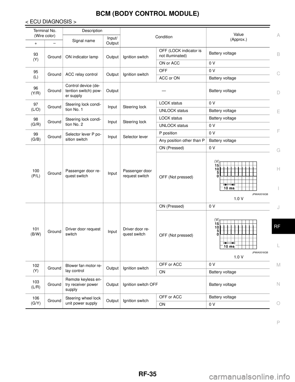
request switchON (Pressed) 0 V
OFF (Not pressed)
1.0 V
101
(B/W)GroundDriver door request
switchInputDriver door re-
quest switchON (Pressed) 0 V
OFF (Not pressed)
1.0 V
102
(Y)GroundBlower fan motor re-
lay controlOutput Ignition switchOFF or ACC 0 V
ON Battery voltage
103
(L/R)GroundRemote keyless en-
try receiver power
supplyOutput Ignition switch OFF Battery voltage
106
(G/Y)GroundSteering wheel lock
unit power supplyOutput Ignition switchOFF or ACC Battery voltage
ON 0 V Te r m i n a l N o .
(Wire color)Description
ConditionVa l u e
(Approx.)
Signal nameInput/
Output +–
JPMIA0016GB
JPMIA0016GB
Page 3833 of 5121
RSU-1
SUSPENSION
C
DF
G H
I
J
K L
M
SECTION RSU
A
B
RSU
N
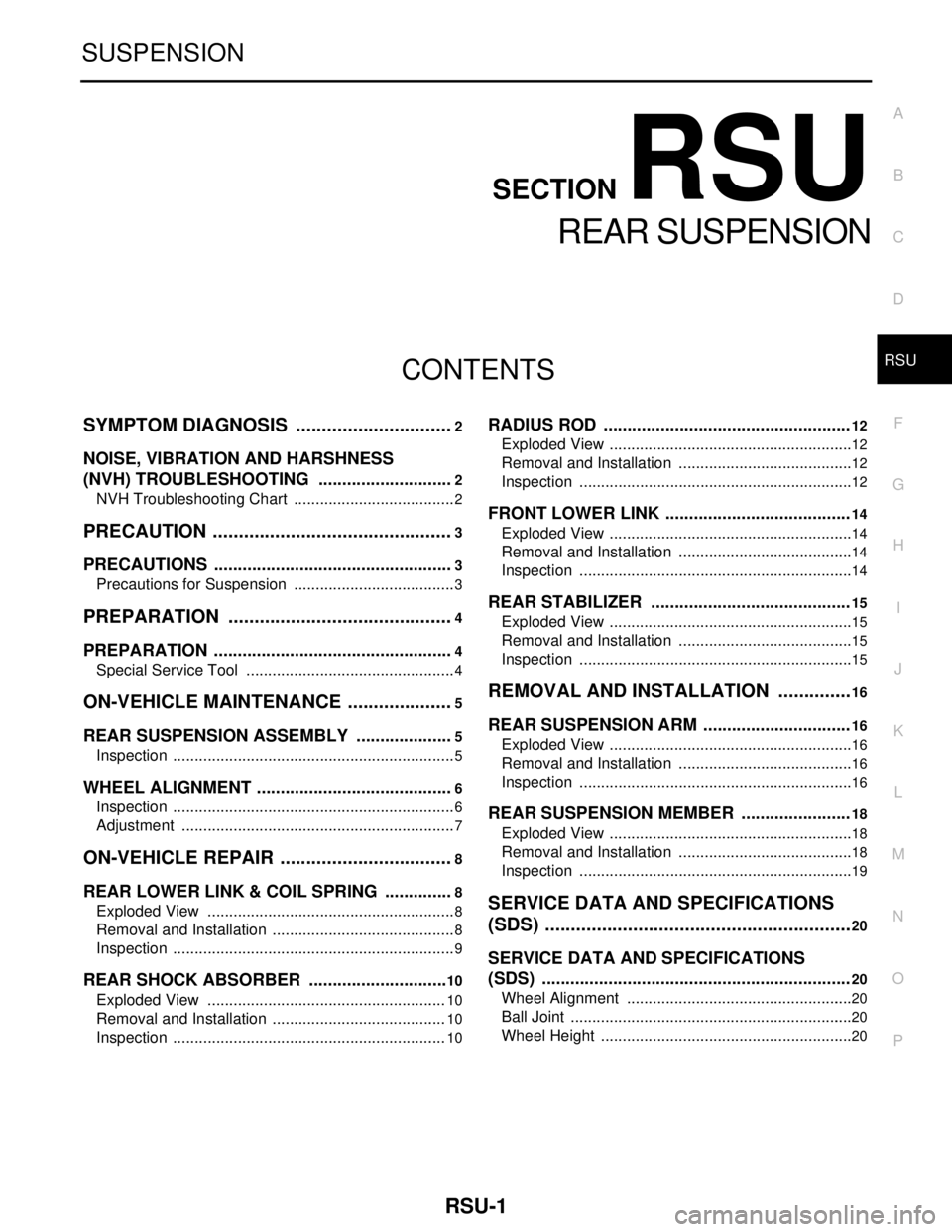
O PCONTENTS
REAR SUSPENSION
SYMPTOM DIAGNOSIS ..... ..........................2
NOISE, VIBRATION AND HARSHNESS
(NVH) TROUBLESHOOTING ........................ .....
2
NVH Troubleshooting Chart ................................ ......2
PRECAUTION ...............................................3
PRECAUTIONS .............................................. .....3
Precautions for Suspension ................................ ......3
PREPARATION ............................................4
PREPARATION .............................................. .....4
Special Service Tool ........................................... ......4
ON-VEHICLE MAINTENANCE .....................5
REAR SUSPENSION ASSEMBLY ................ .....5
Inspection ............................................................ ......5
WHEEL ALIGNMENT ..........................................6
Inspection ............................................................ ......6
Adjustment ................................................................7
ON-VEHICLE REPAIR ..................................8
REAR LOWER LINK & COIL SPRING .......... .....8
Exploded View .................................................... ......8
Removal and Installation ...........................................8
Inspection ..................................................................9
REAR SHOCK ABSORBER ..............................10
Exploded View .................................................... ....10
Removal and Installation .........................................10
Inspection ................................................................10
RADIUS ROD ................................... .................12
Exploded View ..................................................... ....12
Removal and Installation .........................................12
Inspection ................................................................12
FRONT LOWER LINK .......................................14
Exploded View .........................................................14
Removal and Installation .........................................14
Inspection ................................................................14
REAR STABILIZER ..........................................15
Exploded View .........................................................15
Removal and Installation .........................................15
Inspection ................................................................15
REMOVAL AND INSTALLATION ...............16
REAR SUSPENSION ARM ...............................16
Exploded View ..................................................... ....16
Removal and Installation .........................................16
Inspection ................................................................16
REAR SUSPENSION MEMBER .......................18
Exploded View ..................................................... ....18
Removal and Installation .........................................18
Inspection ................................................................19
SERVICE DATA AND SPECIFICATIONS
(SDS) ............... .............................................
20
SERVICE DATA AND SPECIFICATIONS
(SDS) .................................................................
20
Wheel Alignment ................................................. ....20
Ball Joint ..................................................................20
Wheel Height ...........................................................20