2008 NISSAN TEANA wheel
[x] Cancel search: wheelPage 3383 of 5121

PB-2
< ON-VEHICLE MAINTENANCE >
PARKING BRAKE SYSTEM
ON-VEHICLE MAINTENANCE
PARKING BRAKE SYSTEM
Inspection and AdjustmentINFOID:0000000003811312
INSPECTION
Pedal Stroke
1. Operate the parking brake pedal with a force of 196 N (20 kg, 44 lb). Check that the pedal stroke is within
the specified number of notches. (Check it by listening to the clicks of the ratchet.)
2. When brake warning lamp turns ON, check that the pedal stroke is within the specified number of
notches. (Check it by listening to the clicks of the ratchet.)
Inspect Components
• Check each component for installation condition such as looseness.
Check the device assembly for bend, damage and cracks. Replace if necessary.
Check the cables for wear, damage and cracks. Replace if necessary.
Check the parking brake switch, and replace it if necessary. Refer to BRC-41, "
Diagnosis Procedure" (with-
out VDC), BRC-124, "
Component Inspection" (with VDC).
ADJUSTMENT
1. Remove rear tires.
2. Fix the disc rotor using wheel nuts.
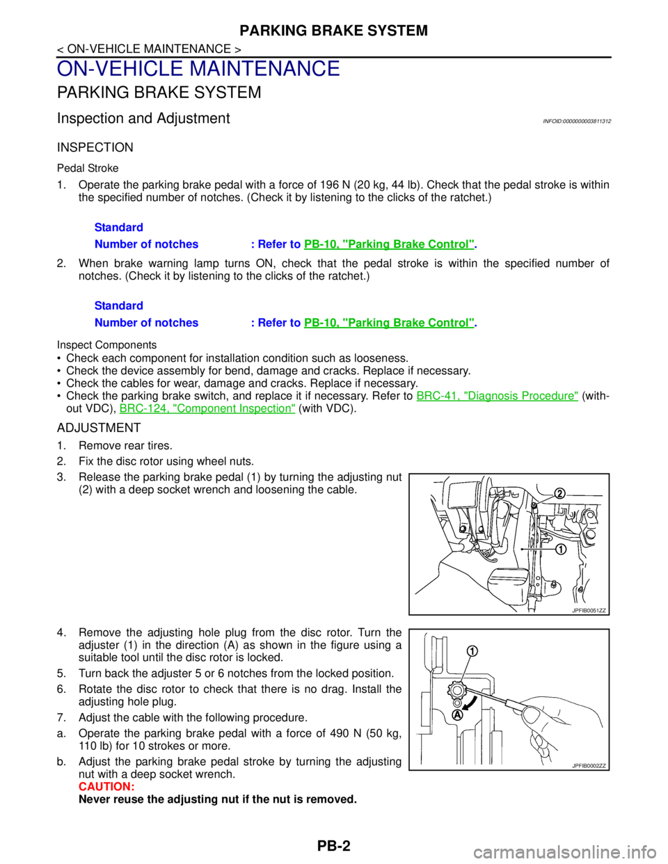
3. Release the parking brake pedal (1) by turning the adjusting nut
(2) with a deep socket wrench and loosening the cable.
4. Remove the adjusting hole plug from the disc rotor. Turn the
adjuster (1) in the direction (A) as shown in the figure using a
suitable tool until the disc rotor is locked.
5. Turn back the adjuster 5 or 6 notches from the locked position.
6. Rotate the disc rotor to check that there is no drag. Install the
adjusting hole plug.
7. Adjust the cable with the following procedure.
a. Operate the parking brake pedal with a force of 490 N (50 kg,
110 lb) for 10 strokes or more.
b. Adjust the parking brake pedal stroke by turning the adjusting
nut with a deep socket wrench.
CAUTION:
Never reuse the adjusting nut if the nut is removed.Standard
Number of notches : Refer to PB-10, "
Parking Brake Control".
Standard
Number of notches : Refer to PB-10, "
Parking Brake Control".
JPFIB0051ZZ
JPFIB0002ZZ
Page 3388 of 5121

PARKING BRAKE SHOE
PB-7
< ON-VEHICLE REPAIR >
C
D
E
G
H
I
J
K
L
MA
B
PB
N
O
P
PARKING BRAKE SHOE
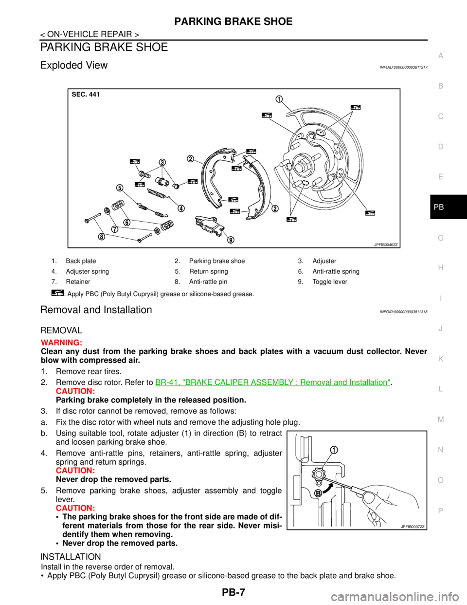
Exploded ViewINFOID:0000000003811317
Removal and InstallationINFOID:0000000003811318
REMOVAL
WARNING:
Clean any dust from the parking brake shoes and back plates with a vacuum dust collector. Never
blow with compressed air.
1. Remove rear tires.
2. Remove disc rotor. Refer to BR-41, "
BRAKE CALIPER ASSEMBLY : Removal and Installation".
CAUTION:
Parking brake completely in the released position.
3. If disc rotor cannot be removed, remove as follows:
a. Fix the disc rotor with wheel nuts and remove the adjusting hole plug.
b. Using suitable tool, rotate adjuster (1) in direction (B) to retract
and loosen parking brake shoe.
4. Remove anti-rattle pins, retainers, anti-rattle spring, adjuster
spring and return springs.
CAUTION:
Never drop the removed parts.
5. Remove parking brake shoes, adjuster assembly and toggle
lever.
CAUTION:
• The parking brake shoes for the front side are made of dif-
ferent materials from those for the rear side. Never misi-
dentify them when removing.
Never drop the removed parts.
INSTALLATION
Install in the reverse order of removal.
Apply PBC (Poly Butyl Cuprysil) grease or silicone-based grease to the back plate and brake shoe.
1. Back plate 2. Parking brake shoe 3. Adjuster
4. Adjuster spring 5. Return spring 6. Anti-rattle spring
7. Retainer 8. Anti-rattle pin 9. Toggle lever
: Apply PBC (Poly Butyl Cuprysil) grease or silicone-based grease.
JPFIB0046ZZ
JPFIB0007ZZ
Page 3393 of 5121

PCS-2
INTELLIGENT KEY : CONSULT-III Function
(BCM - INTELLIGENT KEY) ...................................
42
COMPONENT DIAGNOSIS ........................46
U1000 CAN COMM CIRCUIT ............................46
BCM ...........................................................................46
BCM : Description ...................................................46
BCM : DTC Logic ....................................................46
BCM : Diagnosis Procedure ...................................46
IPDM E/R ...................................................................46
IPDM E/R : Description ...........................................46
IPDM E/R : DTC Logic ............................................46
IPDM E/R : Diagnosis Procedure ...........................46
U1010 CONTROL UNIT (CAN) .........................48
BCM ...........................................................................48
BCM : DTC Logic ....................................................48
BCM : Diagnosis Procedure ...................................48
BCM : Special Repair Requirement ........................48
B2553 IGNITION RELAY ...................................49
Description ..............................................................49
DTC Logic ...............................................................49
Diagnosis Procedure ..............................................49
B260A IGNITION RELAY ..................................51
Description ..............................................................51
DTC Logic ...............................................................51
Diagnosis Procedure ..............................................51
B2614 ACC RELAY ...........................................53
Description ..............................................................53
DTC Logic ...............................................................53
Diagnosis Procedure ..............................................53
Component Inspection ............................................54
B2615 BLOWER RELAY CIRCUIT ...................55
Description ..............................................................55
DTC Logic ...............................................................55
Diagnosis Procedure ..............................................55
Component Inspection ............................................56
B2616 IGNITION RELAY CIRCUIT ...................57
Description ..............................................................57
DTC Logic ...............................................................57
Diagnosis Procedure ..............................................57
Component Inspection ............................................58
B2618 BCM ........................................................59
Description ..............................................................59
DTC Logic ...............................................................59
Diagnosis Procedure ..............................................59
B261A PUSH-BUTTON IGNITION SWITCH .....60
Description ..............................................................60
DTC Logic ...............................................................60
Diagnosis Procedure ..............................................60
POWER SUPPLY AND GROUND CIRCUIT .....62
BCM ...........................................................................62
BCM : Diagnosis Procedure ....................................62
PUSH-BUTTON IGNITION SWITCH .................63
Description ..............................................................63
Component Function Check ..................................63
Diagnosis Procedure ...............................................63
Component Inspection ............................................64
PUSH-BUTTON IGNITION SWITCH POSI-
TION INDICATOR ..............................................
66
Description ..............................................................66
Component Function Check ..................................66
Diagnosis Procedure ...............................................66
Component Inspection ............................................67
POWER DISTRIBUTION SYSTEM ...................68
Wiring Diagram - PDS (POWER DISTRIBUTION
SYSTEM) - ..............................................................
68
ECU DIAGNOSIS .......................................73
BCM (BODY CONTROL MODULE) ..................73
Reference Value .....................................................73
Wiring Diagram - BCM - ..........................................96
Fail-safe ................................................................102
DTC Inspection Priority Chart .............................104
DTC Index ............................................................105
IPDM E/R (INTELLIGENT POWER DISTRI-
BUTION MODULE ENGINE ROOM) ................
107
Reference Value ...................................................107
Wiring Diagram - IPDM E/R - ................................115
Fail-safe ................................................................118
DTC Index ............................................................120
PRECAUTION ...........................................121
PRECAUTIONS ................................................121
Precaution for Supplemental Restraint System
(SRS) "AIR BAG" and "SEAT BELT PRE-TEN-
SIONER" ...............................................................
121
Precaution Necessary for Steering Wheel Rota-
tion after Battery Disconnect .................................
121
SYMPTOM DIAGNOSIS ...........................122
POWER DISTRIBUTION SYSTEM ..................122
Symptom Table .....................................................122
PUSH-BUTTON IGNITION SWITCH DOES
NOT OPERATE ................................................
124
Description ............................................................124
Diagnosis Procedure .............................................124
PUSH-BUTTON IGNITION SWITCH POSI-
TION INDICATOR DOES NOT ILLUMINATE ..
125
Description ............................................................125
Diagnosis Procedure .............................................125
Page 3479 of 5121
![NISSAN TEANA 2008 Service Manual PCS-88
< ECU DIAGNOSIS >[POWER DISTRIBUTION SYSTEM]
BCM (BODY CONTROL MODULE)
93
(Y)Ground ON indicator lamp Output Ignition switchOFF (LOCK indicator is
not illuminated)Battery voltage
ON or ACC 0 V NISSAN TEANA 2008 Service Manual PCS-88
< ECU DIAGNOSIS >[POWER DISTRIBUTION SYSTEM]
BCM (BODY CONTROL MODULE)
93
(Y)Ground ON indicator lamp Output Ignition switchOFF (LOCK indicator is
not illuminated)Battery voltage
ON or ACC 0 V](/manual-img/5/57391/w960_57391-3478.png)
PCS-88
< ECU DIAGNOSIS >[POWER DISTRIBUTION SYSTEM]
BCM (BODY CONTROL MODULE)
93
(Y)Ground ON indicator lamp Output Ignition switchOFF (LOCK indicator is
not illuminated)Battery voltage
ON or ACC 0 V
95
(L)Ground ACC relay control Output Ignition switchOFF 0 V
ACC or ON Battery voltage
96
(Y/R)GroundControl device (de-
tention switch) pow-
er supplyOutput — Battery voltage
97
(L/O)GroundSteering lock condi-
tion No. 1Input Steering lockLOCK status 0 V
UNLOCK status Battery voltage
98
(G/R)GroundSteering lock condi-
tion No. 2Input Steering lockLOCK status Battery voltage
UNLOCK status 0 V
99
(G/B)GroundSelector lever P po-
sition switchInput Selector leverP position 0 V
Any position other than P Battery voltage
100
(P/L)GroundPassenger door re-
quest switchInputPassenger door
request switchON (Pressed) 0 V
OFF (Not pressed)
1.0 V
101
(B/W)GroundDriver door request
switchInputDriver door re-
quest switchON (Pressed) 0 V
OFF (Not pressed)
1.0 V
102
(Y)GroundBlower fan motor re-
lay controlOutput Ignition switchOFF or ACC 0 V
ON Battery voltage
103
(L/R)GroundRemote keyless en-
try receiver power
supplyOutput Ignition switch OFF Battery voltage
106
(G/Y)GroundSteering wheel lock
unit power supplyOutput Ignition switchOFF or ACC Battery voltage
ON 0 V Te r m i n a l N o .
(Wire color)Description
ConditionVa l u e
(Approx.)
Signal nameInput/
Output +–
JPMIA0016GB
JPMIA0016GB
Page 3512 of 5121
![NISSAN TEANA 2008 Service Manual PCS
PRECAUTIONS
PCS-121
< PRECAUTION >[POWER DISTRIBUTION SYSTEM]
C
D
E
F
G
H
I
J
K
L B A
O
P N
PRECAUTION
PRECAUTIONS
Precaution for Supplemental Restraint System (SRS) "AIR BAG" and "SEAT BELT
PRE- NISSAN TEANA 2008 Service Manual PCS
PRECAUTIONS
PCS-121
< PRECAUTION >[POWER DISTRIBUTION SYSTEM]
C
D
E
F
G
H
I
J
K
L B A
O
P N
PRECAUTION
PRECAUTIONS
Precaution for Supplemental Restraint System (SRS) "AIR BAG" and "SEAT BELT
PRE-](/manual-img/5/57391/w960_57391-3511.png)
PCS
PRECAUTIONS
PCS-121
< PRECAUTION >[POWER DISTRIBUTION SYSTEM]
C
D
E
F
G
H
I
J
K
L B A
O
P N
PRECAUTION
PRECAUTIONS
Precaution for Supplemental Restraint System (SRS) "AIR BAG" and "SEAT BELT
PRE-TENSIONER"
INFOID:0000000003940025
The Supplemental Restraint System such as “AIR BAG” and “SEAT BELT PRE-TENSIONER”, used along
with a front seat belt, helps to reduce the risk or severity of injury to the driver and front passenger for certain
types of collision. Information necessary to service the system safely is included in the “SRS AIRBAG” and
“SEAT BELT” of this Service Manual.
WARNING:
To avoid rendering the SRS inoperative, which could increase the risk of personal injury or death in
the event of a collision which would result in air bag inflation, all maintenance must be performed by
an authorized NISSAN/INFINITI dealer.
Improper maintenance, including incorrect removal and installation of the SRS, can lead to personal
injury caused by unintentional activation of the system. For removal of Spiral Cable and Air Bag
Module, see the “SRS AIRBAG”.
Never use electrical test equipment on any circuit related to the SRS unless instructed to in this Ser-
vice Manual. SRS wiring harnesses can be identified by yellow and/or orange harnesses or harness
connectors.
Precaution Necessary for Steering Wheel Rotation after Battery Disconnect
INFOID:0000000003940024
NOTE:
Before removing and installing any control units, first turn the push-button ignition switch to the LOCK posi-
tion, then disconnect both battery cables.
After finishing work, confirm that all control unit connectors are connected properly, then re-connect both
battery cables.
Always use CONSULT-III to perform self-diagnosis as a part of each function inspection after finishing work.
If a DTC is detected, perform trouble diagnosis according to self-diagnosis results.
This vehicle is equipped with a push-button ignition switch and a steering lock unit.
If the battery is disconnected or discharged, the steering wheel will lock and cannot be turned.
If turning the steering wheel is required with the battery disconnected or discharged, follow the procedure
below before starting the repair operation.
OPERATION PROCEDURE
1. Connect both battery cables.
NOTE:
Supply power using jumper cables if battery is discharged.
2. Turn the push-button ignition switch to ACC position.
(At this time, the steering lock will be released.)
3. Disconnect both battery cables. The steering lock will remain released with both battery cables discon-
nected and the steering wheel can be turned.
4. Perform the necessary repair operation.
5. When the repair work is completed, re-connect both battery cables. With the brake pedal released, turn
the push-button ignition switch from ACC position to ON position, then to LOCK position. (The steering
wheel will lock when the push-button ignition switch is turned to LOCK position.)
6. Perform self-diagnosis check of all control units using CONSULT-III.
Page 3632 of 5121

PWC-2
REAR LH ...................................................................23
REAR LH : Description ...........................................23
REAR LH : Component Function Check ................23
REAR LH : Diagnosis Procedure ............................23
REAR LH : Component Inspection .........................24
REAR RH ..................................................................24
REAR RH : Description ..........................................24
REAR RH : Component Function Check ................24
REAR RH : Diagnosis Procedure ...........................25
REAR RH : Component Inspection ........................26
DOOR SWITCH .................................................27
Description ..............................................................27
Component Function Check .................................27
Diagnosis Procedure ..............................................27
Component Inspection ............................................28
ENCODER CIRCUIT ..........................................29
Description ..............................................................29
Component Function Check ...................................29
Diagnosis Procedure ..............................................29
ECU DIAGNOSIS ........................................32
BCM (BODY CONTROL MODULE) ..................32
Reference Value .....................................................32
Wiring Diagram - BCM - .........................................55
Fail-safe ..................................................................61
DTC Inspection Priority Chart ..............................63
DTC Index ..............................................................64
POWER WINDOW MAIN SWITCH ....................66
Reference Value .....................................................66
Wiring Diagram - POWER WINDOW SYSTEM - ...68
Fail-safe ..................................................................72
SYMPTOM DIAGNOSIS .............................74
POWER WINDOWS DO NOT OPERATE
WITH ANY POWER WINDOW SWITCHES ......
74
Diagnosis Procedure ..............................................74
DRIVER SIDE POWER WINDOW DOES NOT
OPERATE ..........................................................
75
Diagnosis Procedure ..............................................75
FRONT PASSENGER SIDE POWER WIN-
DOW DOES NOT OPERATE ............................
76
WITH BOTH POWER WINDOW MAIN SWITCH
AND FRONT PASSENGER SIDE POWER WIN-
DOW SWITCH ...........................................................
76
WITH BOTH POWER WINDOW MAIN SWITCH
AND FRONT PASSENGER SIDE POWER WIN-
DOW SWITCH : Diagnosis Procedure ...................
76
POWER WINDOW MAIN SWITCH IS OPERATED ...76
POWER WINDOW MAIN SWITCH IS OPERAT-
ED : Diagnosis Procedure ......................................
76
REAR LH SIDE POWER WINDOW DOES
NOT OPERATE .................................................
77
WITH BOTH POWER WINDOW MAIN SWITCH
AND REAR POWER WINDOW SWITCH LH ............
77
WITH BOTH POWER WINDOW MAIN SWITCH
AND REAR POWER WINDOW SWITCH LH : Di-
agnosis Procedure ..................................................
77
WITH REAR POWER WINDOW SWITCH LH
ONLY .........................................................................
77
WITH REAR POWER WINDOW SWITCH LH
ONLY : Diagnosis Procedure ..................................
77
REAR RH SIDE POWER WINDOW DOES
NOT OPERATE .................................................
78
WITH BOTH POWER WINDOW MAIN SWITCH
AND REAR POWER WINDOW SWITCH RH ...........
78
WITH BOTH POWER WINDOW MAIN SWITCH
AND REAR POWER WINDOW SWITCH RH : Di-
agnosis Procedure ..................................................
78
WITH REAR POWER WINDOW SWITCH RH
ONLY .........................................................................
78
WITH REAR POWER WINDOW SWITCH RH
ONLY : Diagnosis Procedure ..................................
78
ANTI-PINCH SYSTEM DOES NOT OPERATE
NORMALLY (DRIVER SIDE) ............................
79
Diagnosis Procedure ...............................................79
POWER WINDOW RETAINED POWER OP-
ERATION DOES NOT OPERATE PROPERLY
...
80
Diagnosis Procedure ...............................................80
AUTO OPERATION DOES NOT OPERATE
BUT MANUAL OPERATE NORMALLY
(DRIVER SIDE) ..................................................
81
Diagnosis Procedure ...............................................81
POWER WINDOW LOCK SWITCH DOES
NOT FUNCTION ................................................
82
Diagnosis Procedure ...............................................82
POWER WINDOW SWITCH DOES NOT IL-
LUMINATE .........................................................
83
Diagnosis Procedure ...............................................83
PRECAUTION ............................................84
PRECAUTIONS .................................................84
Precaution for Supplemental Restraint System
(SRS) "AIR BAG" and "SEAT BELT PRE-TEN-
SIONER" .................................................................
84
Precaution Necessary for Steering Wheel Rota-
tion after Battery Disconnect ...................................
84
ON-VEHICLE REPAIR ...............................85
POWER WINDOW MAIN SWITCH ...................85
Page 3677 of 5121

BCM (BODY CONTROL MODULE)
PWC-47
< ECU DIAGNOSIS >
C
D
E
F
G
H
I
J
L
MA
B
PWC
N
O
P
93
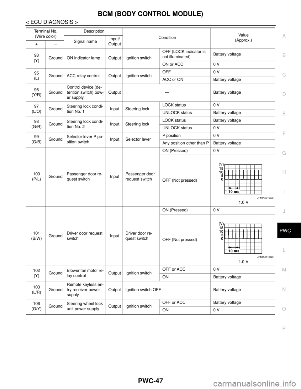
(Y)Ground ON indicator lamp Output Ignition switchOFF (LOCK indicator is
not illuminated)Battery voltage
ON or ACC 0 V
95
(L)Ground ACC relay control Output Ignition switchOFF 0 V
ACC or ON Battery voltage
96
(Y/R)GroundControl device (de-
tention switch) pow-
er supplyOutput — Battery voltage
97
(L/O)GroundSteering lock condi-
tion No. 1Input Steering lockLOCK status 0 V
UNLOCK status Battery voltage
98
(G/R)GroundSteering lock condi-
tion No. 2Input Steering lockLOCK status Battery voltage
UNLOCK status 0 V
99
(G/B)GroundSelector lever P po-
sition switchInput Selector leverP position 0 V
Any position other than P Battery voltage
100
(P/L)GroundPassenger door re-
quest switchInputPassenger door
request switchON (Pressed) 0 V
OFF (Not pressed)
1.0 V
101
(B/W)GroundDriver door request
switchInputDriver door re-
quest switchON (Pressed) 0 V
OFF (Not pressed)
1.0 V
102
(Y)GroundBlower fan motor re-
lay controlOutput Ignition switchOFF or ACC 0 V
ON Battery voltage
103
(L/R)GroundRemote keyless en-
try receiver power
supplyOutput Ignition switch OFF Battery voltage
106
(G/Y)GroundSteering wheel lock
unit power supplyOutput Ignition switchOFF or ACC Battery voltage
ON 0 V Te r m i n a l N o .
(Wire color)Description
ConditionVa l u e
(Approx.)
Signal nameInput/
Output +–
JPMIA0016GB
JPMIA0016GB
Page 3714 of 5121

PWC-84
< PRECAUTION >
PRECAUTIONS
PRECAUTION
PRECAUTIONS
Precaution for Supplemental Restraint System (SRS) "AIR BAG" and "SEAT BELT
PRE-TENSIONER"
INFOID:0000000003826050
The Supplemental Restraint System such as “AIR BAG” and “SEAT BELT PRE-TENSIONER”, used along
with a front seat belt, helps to reduce the risk or severity of injury to the driver and front passenger for certain
types of collision. This system includes seat belt switch inputs and dual stage front air bag modules. The SRS
system uses the seat belt switches to determine the front air bag deployment, and may only deploy one front
air bag, depending on the severity of a collision and whether the front occupants are belted or unbelted.
Information necessary to service the system safely is included in the “SRS AIRBAG” and “SEAT BELT” of this
Service Manual.
WARNING:
To avoid rendering the SRS inoperative, which could increase the risk of personal injury or death in
the event of a collision which would result in air bag inflation, all maintenance must be performed by
an authorized NISSAN/INFINITI dealer.
Improper maintenance, including incorrect removal and installation of the SRS, can lead to personal
injury caused by unintentional activation of the system. For removal of Spiral Cable and Air Bag
Module, see the “SRS AIRBAG”.
Never use electrical test equipment on any circuit related to the SRS unless instructed to in this Ser-
vice Manual. SRS wiring harnesses can be identified by yellow and/or orange harnesses or harness
connectors.
Precaution Necessary for Steering Wheel Rotation after Battery Disconnect
INFOID:0000000003826051
NOTE:
Before removing and installing any control units, first turn the push-button ignition switch to the LOCK posi-
tion, then disconnect both battery cables.
After finishing work, confirm that all control unit connectors are connected properly, then re-connect both
battery cables.
Always use CONSULT-III to perform self-diagnosis as a part of each function inspection after finishing work.
If a DTC is detected, perform trouble diagnosis according to self-diagnosis results.
This vehicle is equipped with a push-button ignition switch and a steering lock unit.
If the battery is disconnected or discharged, the steering wheel will lock and cannot be turned.
If turning the steering wheel is required with the battery disconnected or discharged, follow the procedure
below before starting the repair operation.
OPERATION PROCEDURE
1. Connect both battery cables.
NOTE:
Supply power using jumper cables if battery is discharged.
2. Turn the push-button ignition switch to ACC position.
(At this time, the steering lock will be released.)
3. Disconnect both battery cables. The steering lock will remain released with both battery cables discon-
nected and the steering wheel can be turned.
4. Perform the necessary repair operation.
5. When the repair work is completed, re-connect both battery cables. With the brake pedal released, turn
the push-button ignition switch from ACC position to ON position, then to LOCK position. (The steering
wheel will lock when the push-button ignition switch is turned to LOCK position.)
6. Perform self-diagnosis check of all control units using CONSULT-III.