2008 NISSAN TEANA sensor
[x] Cancel search: sensorPage 4410 of 5121
ST-20
< ON-VEHICLE REPAIR >
STEERING GEAR AND LINKAGE
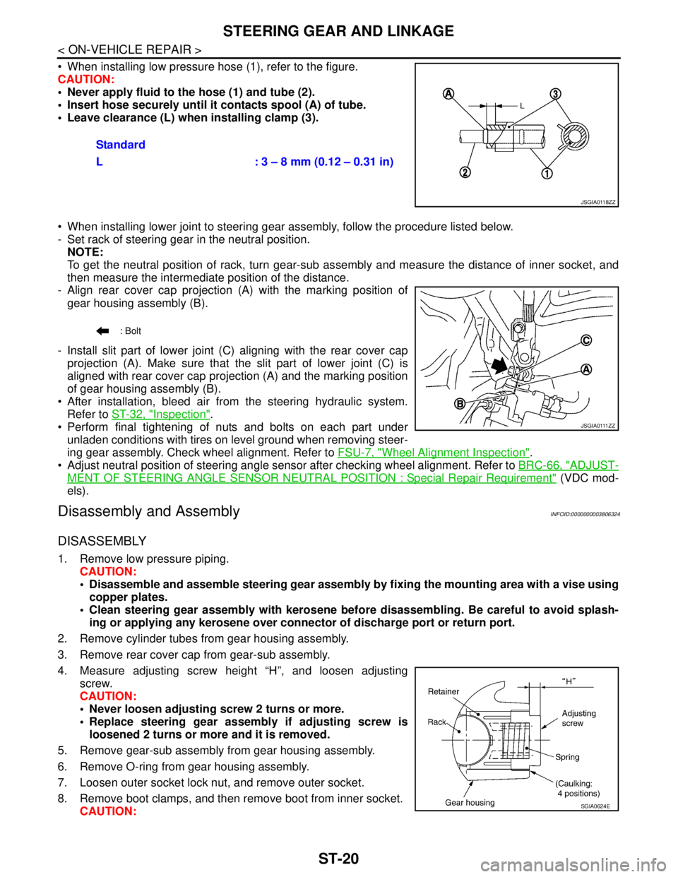
When installing low pressure hose (1), refer to the figure.
CAUTION:
Never apply fluid to the hose (1) and tube (2).
Insert hose securely until it contacts spool (A) of tube.
Leave clearance (L) when installing clamp (3).
When installing lower joint to steering gear assembly, follow the procedure listed below.
- Set rack of steering gear in the neutral position.
NOTE:
To get the neutral position of rack, turn gear-sub assembly and measure the distance of inner socket, and
then measure the intermediate position of the distance.
- Align rear cover cap projection (A) with the marking position of
gear housing assembly (B).
- Install slit part of lower joint (C) aligning with the rear cover cap
projection (A). Make sure that the slit part of lower joint (C) is
aligned with rear cover cap projection (A) and the marking position
of gear housing assembly (B).
After installation, bleed air from the steering hydraulic system.
Refer to ST-32, "
Inspection".
Perform final tightening of nuts and bolts on each part under
unladen conditions with tires on level ground when removing steer-
ing gear assembly. Check wheel alignment. Refer to FSU-7, "
Wheel Alignment Inspection".
Adjust neutral position of steering angle sensor after checking wheel alignment. Refer to BRC-66, "
ADJUST-
MENT OF STEERING ANGLE SENSOR NEUTRAL POSITION : Special Repair Requirement" (VDC mod-
els).
Disassembly and AssemblyINFOID:0000000003806324
DISASSEMBLY
1. Remove low pressure piping.
CAUTION:
Disassemble and assemble steering gear assembly by fixing the mounting area with a vise using
copper plates.
Clean steering gear assembly with kerosene before disassembling. Be careful to avoid splash-
ing or applying any kerosene over connector of discharge port or return port.
2. Remove cylinder tubes from gear housing assembly.
3. Remove rear cover cap from gear-sub assembly.
4. Measure adjusting screw height “H”, and loosen adjusting
screw.
CAUTION:
Never loosen adjusting screw 2 turns or more.
Replace steering gear assembly if adjusting screw is
loosened 2 turns or more and it is removed.
5. Remove gear-sub assembly from gear housing assembly.
6. Remove O-ring from gear housing assembly.
7. Loosen outer socket lock nut, and remove outer socket.
8. Remove boot clamps, and then remove boot from inner socket.
CAUTION:Standard
L : 3 – 8 mm (0.12 – 0.31 in)
JSGIA0118ZZ
: Bolt
J S G I A 0 111 Z Z
SGIA0624E
Page 4419 of 5121
POWER STEERING OIL PUMP
ST-29
< ON-VEHICLE REPAIR >
C
D
E
F
H
I
J
K
L
MA
B
ST
N
O
P
Removal and InstallationINFOID:0000000003806327
REMOVAL
1. Drain power steering fluid from reservoir tank.
2. Remove front tires.
3. Remove splash guard. Refer to EXT-22, "
FENDER PROTECTOR : Exploded View".
4. Loosen drive belt. Refer to EM-12, "
Removal and Installation".
5. Remove drive belt from oil pump pulley.
6. Remove copper washers and eye bolt (drain fluid from their pipings).
7. Remove suction hose (drain fluid from their pipings).
8. Remove oil pump mounting bolts, and then remove oil pump.
CAUTION:
Never damage drive shaft boot.
INSTALLATION
Note the following, and install in the reverse order of removal.
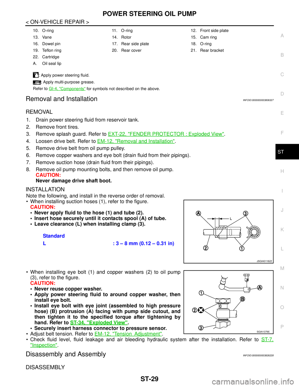
When installing suction hoses (1), refer to the figure.
CAUTION:
Never apply fluid to the hose (1) and tube (2).
Insert hose securely until it contacts spool (A) of tube.
Leave clearance (L) when installing clamp (3).
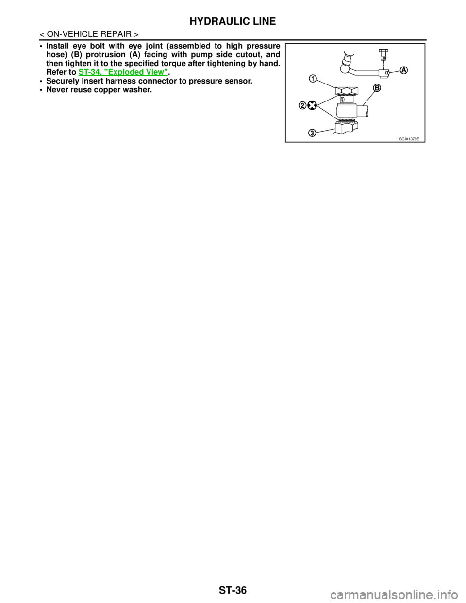
When installing eye bolt (1) and copper washers (2) to oil pump
(3), refer to the figure.
CAUTION:
Never reuse copper washer.
Apply power steering fluid to around copper washer, then
install eye bolt.
Install eye bolt with eye joint (assembled to high pressure
hose) (B) protrusion (A) facing with pump side cutout, and
then tighten it to the specified torque after tightening by
hand. Refer to ST-34, "
Exploded View".
Securely insert harness connector to pressure sensor.
Adjust belt tension. Refer to EM-12, "
TensionAdjustment".
Check fluid level, fluid leakage and air bleeding hydraulic system after the installation. Refer to ST-7,
"Inspection".
Disassembly and AssemblyINFOID:0000000003826228
DISASSEMBLY
10. O-ring 11. O-ring 12. Front side plate
13. Vane 14. Rotor 15. Cam ring
16. Dowel pin 17. Rear side plate 18. O-ring
19. Teflon ring 20. Rear cover 21. Rear bracket
22. Cartridge
A. Oil seal lip
: Apply power steering fluid.
: Apply multi-purpose grease.
Refer to GI-4, "
Components" for symbols not described on the above.
Standard
L : 3 – 8 mm (0.12 – 0.31 in)
JSGIA0118ZZ
SGIA1379E
Page 4422 of 5121
ST-32
< ON-VEHICLE REPAIR >
POWER STEERING OIL PUMP
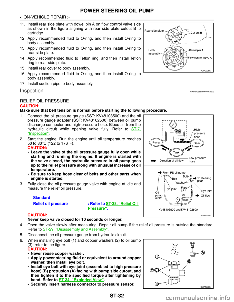
11. Install rear side plate with dowel pin A on flow control valve side
as shown in the figure aligning with rear side plate cutout B to
cartridge.
12. Apply recommended fluid to O-ring, and then install O-ring to
body assembly.
13. Apply recommended fluid to O-ring, and then install O-ring to
rear side plate.
14. Apply recommended fluid to Teflon ring, and then install Teflon
ring to rear side plate.
15. Install rear cover to body assembly.
16. Apply recommended fluid to O-ring, and then install O-ring to
body assembly.
17. Install suction pipe to body assembly.
InspectionINFOID:0000000003806329
RELIEF OIL PRESSURE
CAUTION:
Make sure that belt tension is normal before starting the following procedure.
1. Connect the oil pressure gauge (SST: KV48103500) and the oil
pressure gauge adapter (SST: KV48102500) between oil pump
discharge connector and high-pressure hose. Bleed air from the
hydraulic circuit while opening valve fully. Refer to ST-7,
"Inspection".
2. Start the engine. Run the engine until oil temperature reaches
50 to 80°C (122 to 176°F).
CAUTION:
Leave the valve of the oil pressure gauge fully open while
starting and running the engine. If engine is started with
the valve closed, the hydraulic pressure in oil pump goes
up to the relief pressure along with unusual increase of oil
temperature.
Be sure to keep hose clear of belts and other parts when
engine is started.
3. Fully close the oil pressure gauge valve with engine at idle and
measure the relief oil pressure.
CAUTION:
Never keep valve closed for 10 seconds or longer.
4. Open the valve slowly after measuring. Repair oil pump if the relief oil pressure is outside the standard.
Refer to ST-29, "
Disassembly and Assembly".
5. Disconnect the oil pressure gauge from hydraulic circuit.
6. When installing eye bolt (1) and copper washers (2) to oil pump
(3), refer to the figure.
CAUTION:
Never reuse copper washer.
Apply power steering fluid or equivalent to around copper
washer, then install eye bolt.
Install eye bolt with eye joint (assembled to high pressure
hose) (B) protrusion (A) facing with pump side cutout, and
then tighten it to the specified torque after tightening by
hand. Refer to ST-34, "
Exploded View".
Securely insert harness connector to pressure sensor.
PGIA0035E
Standard
Relief oil pressure : Refer to ST-38, "
Relief Oil
Pressure".
SGIA1225E
SGIA1379E
Page 4424 of 5121
ST-34
< ON-VEHICLE REPAIR >
HYDRAULIC LINE
HYDRAULIC LINE
Exploded ViewINFOID:0000000003806330
VQ25DE Models
JSGIA0401GB
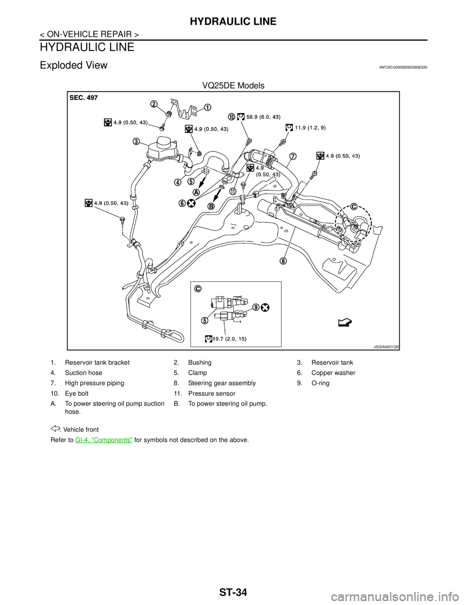
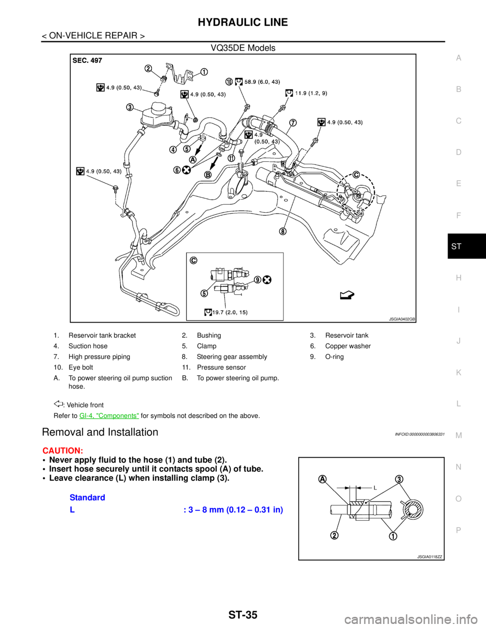
1. Reservoir tank bracket 2. Bushing 3. Reservoir tank
4. Suction hose 5. Clamp 6. Copper washer
7. High pressure piping 8. Steering gear assembly 9. O-ring
10. Eye bolt 11. Pressure sensor
A. To power steering oil pump suction
hose.B. To power steering oil pump.
: Vehicle front
Refer to GI-4, "
Components" for symbols not described on the above.
Page 4425 of 5121
HYDRAULIC LINE
ST-35
< ON-VEHICLE REPAIR >
C
D
E
F
H
I
J
K
L
MA
B
ST
N
O
P
VQ35DE Models
Removal and InstallationINFOID:0000000003806331
CAUTION:
Never apply fluid to the hose (1) and tube (2).
Insert hose securely until it contacts spool (A) of tube.
Leave clearance (L) when installing clamp (3).
JSGIA0402GB
1. Reservoir tank bracket 2. Bushing 3. Reservoir tank
4. Suction hose 5. Clamp 6. Copper washer
7. High pressure piping 8. Steering gear assembly 9. O-ring
10. Eye bolt 11. Pressure sensor
A. To power steering oil pump suction
hose.B. To power steering oil pump.
: Vehicle front
Refer to GI-4, "
Components" for symbols not described on the above.
Standard
L : 3 – 8 mm (0.12 – 0.31 in)
JSGIA0118ZZ
Page 4426 of 5121
ST-36
< ON-VEHICLE REPAIR >
HYDRAULIC LINE
Install eye bolt with eye joint (assembled to high pressure
hose) (B) protrusion (A) facing with pump side cutout, and
then tighten it to the specified torque after tightening by hand.
Refer to ST-34, "
Exploded View".
Securely insert harness connector to pressure sensor.
Never reuse copper washer.
SGIA1379E
Page 4433 of 5121
EPS SYSTEM
STC-5
< FUNCTION DIAGNOSIS >
C
D
E
F
H
I
J
K
L
MA
B
STC
N
O
P
Component Parts LocationINFOID:0000000003893524
Component DescriptionINFOID:0000000003893525
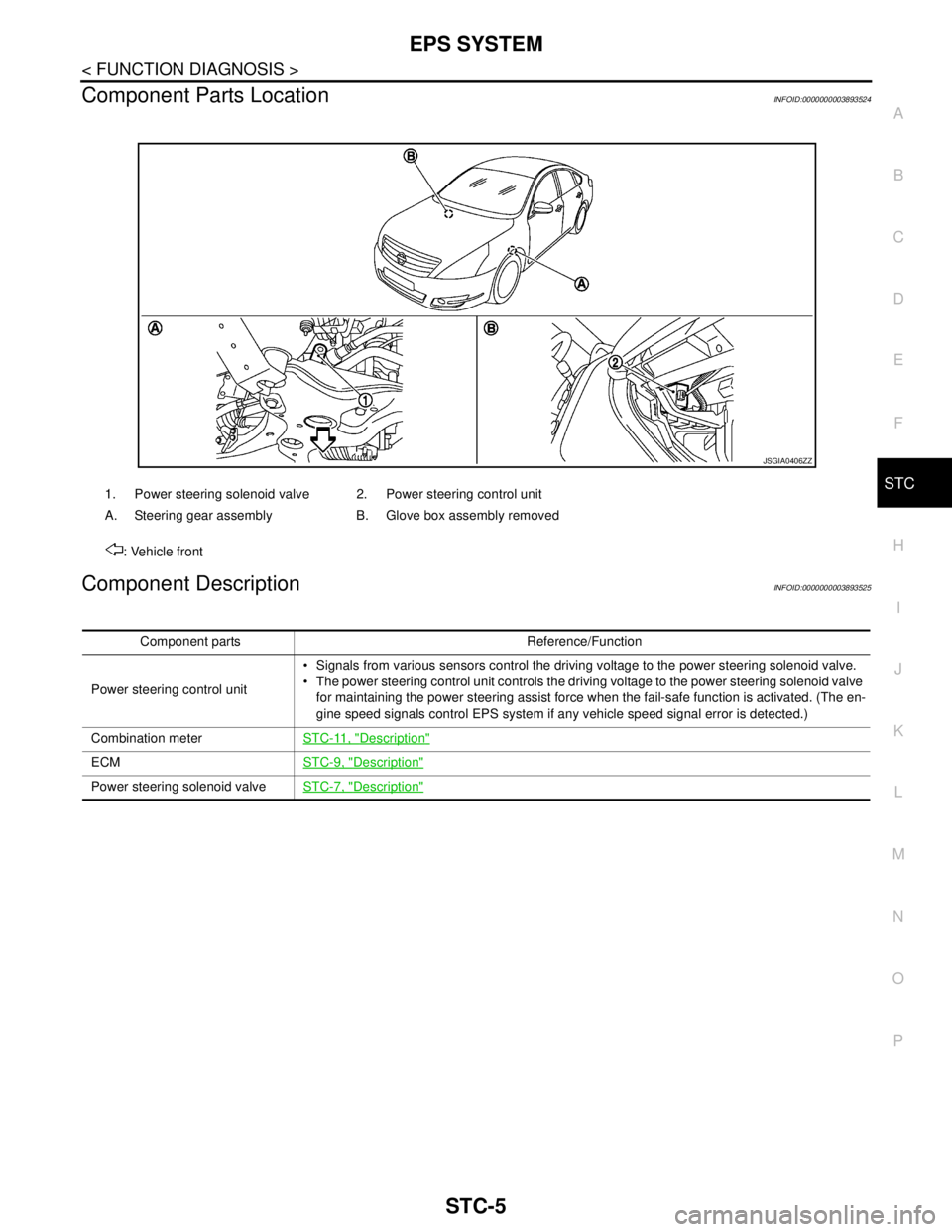
1. Power steering solenoid valve 2. Power steering control unit
A. Steering gear assembly B. Glove box assembly removed
: Vehicle front
JSGIA0406ZZ
Component parts Reference/Function
Power steering control unit Signals from various sensors control the driving voltage to the power steering solenoid valve.
The power steering control unit controls the driving voltage to the power steering solenoid valve
for maintaining the power steering assist force when the fail-safe function is activated. (The en-
gine speed signals control EPS system if any vehicle speed signal error is detected.)
Combination meterSTC-11, "
Description"
ECMSTC-9, "Description"
Power steering solenoid valveSTC-7, "Description"
Page 4475 of 5121

TM-2
DTC Logic ...............................................................47
Diagnosis Procedure ..............................................47
Component Inspection ............................................48
P0710 CVT FLUID TEMPERATURE SENSOR
...
50
Description ..............................................................50
DTC Logic ...............................................................50
Diagnosis Procedure ..............................................50
Component Inspection (CVT Fluid Temperature
Sensor) ...................................................................
51
P0715 INPUT SPEED SENSOR (PRI SPEED
SENSOR) ...........................................................
52
Description ..............................................................52
DTC Logic ...............................................................52
Diagnosis Procedure ..............................................52
P0720 VEHICLE SPEED SENSOR CVT (SEC-
ONDARY SPEED SENSOR) .............................
55
Description ..............................................................55
DTC Logic ...............................................................55
Diagnosis Procedure ..............................................55
P0725 ENGINE SPEED SIGNAL ......................59
Description ..............................................................59
DTC Logic ...............................................................59
Diagnosis Procedure ..............................................59
P0730 BELT DAMAGE ......................................60
Description ..............................................................60
DTC Logic ...............................................................60
Diagnosis Procedure ..............................................60
P0740 TORQUE CONVERTER CLUTCH SO-
LENOID VALVE .................................................
62
Description ..............................................................62
DTC Logic ...............................................................62
Diagnosis Procedure ..............................................62
Component Inspection (Torque Converter Clutch
Solenoid Valve) ......................................................
63
P0744 A/T TCC S/V FUNCTION (LOCK -UP) ...64
Description ..............................................................64
DTC Logic ...............................................................64
Diagnosis Procedure ..............................................64
Component Inspection (Torque Converter Clutch
Solenoid Valve) ......................................................
65
Component Inspection (Lock-up Select Solenoid
Valve) .....................................................................
65
P0745 LINE PRESSURE SOLENOID VALVE ...66
Description ..............................................................66
DTC Logic ...............................................................66
Diagnosis Procedure ..............................................66
Component Inspection [Pressure Control Sole-
noid Valve A (Line Pressure Solenoid Valve)] ........
67
P0746 PRESSURE CONTROL SOLENOID A
PERFORMANCE (LINE PRESSURE SOLE-
NOID VALVE) ....................................................
68
Description ..............................................................68
DTC Logic ...............................................................68
Diagnosis Procedure ...............................................68
Component Inspection [Pressure Control Sole-
noid Valve A (Line Pressure Solenoid Valve)] ........
69
P0776 PRESSURE CONTROL SOLENOID B
PERFORMANCE (SEC PRESSURE SOLE-
NOID VALVE) ....................................................
70
Description ..............................................................70
DTC Logic ...............................................................70
Diagnosis Procedure ...............................................70
Component Inspection [Pressure Control Sole-
noid Valve A (Line Pressure Solenoid Valve)] ........
71
Component Inspection [Pressure Control Sole-
noid Valve B (Secondary Pressure Solenoid
Valve)] .....................................................................
71
P0778 PRESSURE CONTROL SOLENOID B
ELECTRICAL (SEC PRESSURE SOLENOID
VALVE) ..............................................................
72
Description ..............................................................72
DTC Logic ...............................................................72
Diagnosis Procedure ...............................................72
Component Inspection [Pressure Control Sole-
noid Valve B (Secondary Pressure Solenoid
Valve)] .....................................................................
73
P0840 TRANSMISSION FLUID PRESSURE
SENSOR A (SEC PRESSURE SENSOR) .........
74
Description ..............................................................74
DTC Logic ...............................................................74
Diagnosis Procedure ...............................................74
P0841 PRESSURE SENSOR FUNCTION ........77
Description ..............................................................77
DTC Logic ...............................................................77
Diagnosis Procedure ...............................................77
Component Inspection [Pressure Control Sole-
noid Valve A (Line Pressure Solenoid Valve)] ........
78
Component Inspection [Pressure Control Sole-
noid Valve B (Secondary Pressure Solenoid
Valve)] .....................................................................
78
P0845 TRANSMISSION FLUID PRESSURE
SENSOR B (PRI PRESSURE SENSOR) ..........
80
Description ..............................................................80
DTC Logic ...............................................................80
Diagnosis Procedure ...............................................80
P0868 SECONDARY PRESSURE DOWN ........83
Description ..............................................................83
DTC Logic ...............................................................83
Diagnosis Procedure ...............................................83
Component Inspection [Pressure Control Sole-
noid Valve A (Line Pressure Solenoid Valve)] ........
84