Page 4384 of 5121
DIAGNOSIS SENSOR UNIT
SRC-141
< ECU DIAGNOSIS >
C
D
E
F
G
I
J
K
L
MA
B
SRC
N
O
P
JCHWM0190GB
Page 4385 of 5121
SRC-142
< ECU DIAGNOSIS >
DIAGNOSIS SENSOR UNIT
JCHWM0191GB
Page 4386 of 5121
DIAGNOSIS SENSOR UNIT
SRC-143
< ECU DIAGNOSIS >
C
D
E
F
G
I
J
K
L
MA
B
SRC
N
O
P
JCHWM0192GB
Page 4387 of 5121
SRC-144
< ECU DIAGNOSIS >
DIAGNOSIS SENSOR UNIT
JCHWM0193GB
Page 4389 of 5121
SRC-146
< SYMPTOM DIAGNOSIS >
SRS AIR BAG WARNING LAMP DOES NOT TURN ON
SRS AIR BAG WARNING LAMP DOES NOT TURN ON
Diagnosis ProcedureINFOID:0000000003814107
1.CHECK METER FUSE
Check the meter fuse. Refer to PG-82, "
Fuse".
Is 10A fuse [No.4, located in fuse block (J/B)] normal?
YES >> GO TO 3.
NO >> Replace the fuse GO TO 2.
2.CHECK METER FUSE AGAIN
Turn ignition switch ON.
Check the meter fuse. Refer to PG-82, "
Fuse".
Did the meter fuse blow again?
YES >> Repair or replace the related harness.
NO >> INSPECTION END
3.CHECK HARNESS CONNECTION
1. Check harness connection between air bag diagnosis sensor unit and combination meter.
2. Disconnect air bag diagnosis sensor unit connector and turn ignition switch ON.
Did air bag warning lamp turn ON?
YES >> Replace air bag diagnosis sensor unit. Refer to SR-22, "Exploded View".
NO >> Replace combination meter assembly. Refer to MWI-127, "
Exploded View".
Page 4390 of 5121

PRECAUTIONS
SRC-147
< PRECAUTION >
C
D
E
F
G
I
J
K
L
MA
B
SRC
N
O
P
PRECAUTION
PRECAUTIONS
Precaution for Supplemental Restraint System (SRS) "AIR BAG" and "SEAT BELT
PRE-TENSIONER"
INFOID:0000000003814141
The Supplemental Restraint System such as “AIR BAG” and “SEAT BELT PRE-TENSIONER”, used along
with a front seat belt, helps to reduce the risk or severity of injury to the driver and front passenger for certain
types of collision. Information necessary to service the system safely is included in the “SRS AIRBAG” and
“SEAT BELT” of this Service Manual.
WARNING:
To avoid rendering the SRS inoperative, which could increase the risk of personal injury or death in
the event of a collision which would result in air bag inflation, all maintenance must be performed by
an authorized NISSAN/INFINITI dealer.
Improper maintenance, including incorrect removal and installation of the SRS, can lead to personal
injury caused by unintentional activation of the system. For removal of Spiral Cable and Air Bag
Module, see the “SRS AIRBAG”.
Never use electrical test equipment on any circuit related to the SRS unless instructed to in this Ser-
vice Manual. SRS wiring harnesses can be identified by yellow and/or orange harnesses or harness
connectors.
ServiceINFOID:0000000003814109
Do not use electrical test equipment to check SRS circuits unless instructed to in this Service Manual.
Before servicing the SRS, turn ignition switch OFF, disconnect battery negative terminal and wait at least 3
minutes.
For approximately 3 minutes after the battery negative terminal is removed, it is still possible for the air bag
and seat belt pre-tensioner to deploy. Therefore, do not work on any SRS connectors or wires until at least 3
minutes have elapsed.
Diagnosis sensor unit must always be installed with their arrow marks “⇐” pointing towards the front of the
vehicle for proper operation. Also check diagnosis sensor unit for cracks, deformities or rust before installa-
tion and replace as required.
The spiral cable must be aligned in the neutral position since its rotations are limited. Do not turn steering
wheel and column after removal of steering gear.
Handle air bag module carefully. Always place driver and front passenger air bag modules with the pad side
facing upward and seat mounted front side air bag module standing with the stud bolt side facing down.
Conduct self-diagnosis to check entire SRS for proper function after replacing any components.
After air bag inflates, the front instrument panel assembly should be replaced if damaged.
Always replace instrument panel pad following front passenger air bag deployment.
Page 4404 of 5121

ST-14
< ON-VEHICLE REPAIR >
STEERING COLUMN
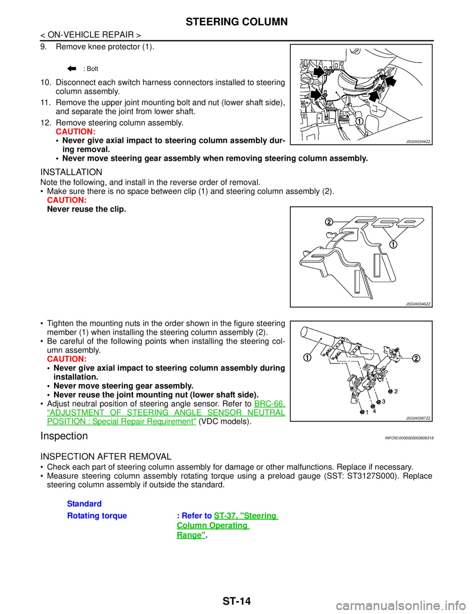
9. Remove knee protector (1).
10. Disconnect each switch harness connectors installed to steering
column assembly.
11. Remove the upper joint mounting bolt and nut (lower shaft side),
and separate the joint from lower shaft.
12. Remove steering column assembly.
CAUTION:
Never give axial impact to steering column assembly dur-
ing removal.
Never move steering gear assembly when removing steering column assembly.
INSTALLATION
Note the following, and install in the reverse order of removal.
Make sure there is no space between clip (1) and steering column assembly (2).
CAUTION:
Never reuse the clip.
Tighten the mounting nuts in the order shown in the figure steering
member (1) when installing the steering column assembly (2).
Be careful of the following points when installing the steering col-
umn assembly.
CAUTION:
Never give axial impact to steering column assembly during
installation.
Never move steering gear assembly.
Never reuse the joint mounting nut (lower shaft side).
Adjust neutral position of steering angle sensor. Refer to BRC-66,
"ADJUSTMENT OF STEERING ANGLE SENSOR NEUTRAL
POSITION : Special Repair Requirement" (VDC models).
InspectionINFOID:0000000003806318
INSPECTION AFTER REMOVAL
Check each part of steering column assembly for damage or other malfunctions. Replace if necessary.
Measure steering column assembly rotating torque using a preload gauge (SST: ST3127S000). Replace
steering column assembly if outside the standard.
: Bolt
JSGIA0344ZZ
JSGIA0346ZZ
JSGIA0387ZZ
Standard
Rotating torque : Refer to ST-37, "
Steering
Column Operating
Range".
Page 4407 of 5121

LOWER SHAFT
ST-17
< ON-VEHICLE REPAIR >
C
D
E
F
H
I
J
K
L
MA
B
ST
N
O
P
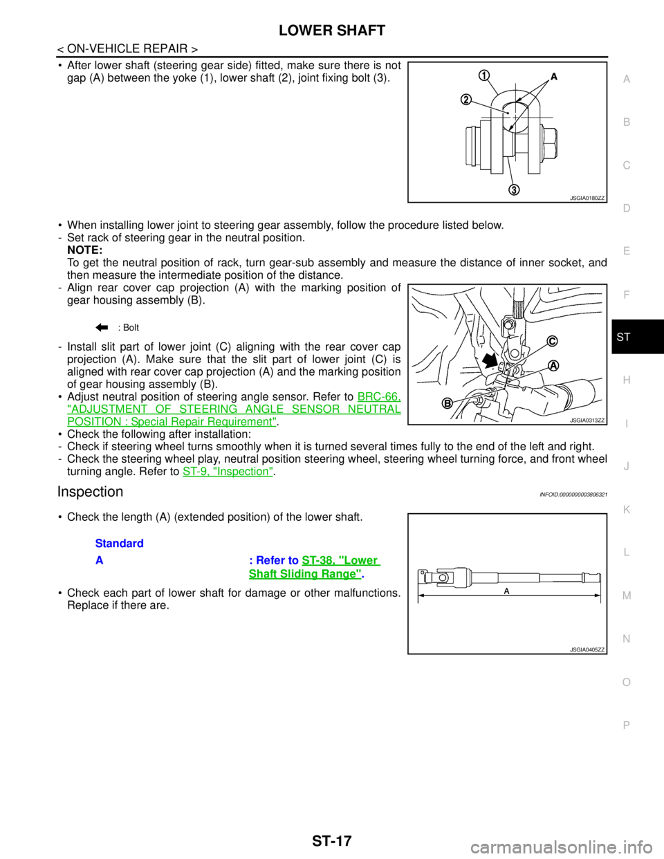
After lower shaft (steering gear side) fitted, make sure there is not
gap (A) between the yoke (1), lower shaft (2), joint fixing bolt (3).
When installing lower joint to steering gear assembly, follow the procedure listed below.
- Set rack of steering gear in the neutral position.
NOTE:
To get the neutral position of rack, turn gear-sub assembly and measure the distance of inner socket, and
then measure the intermediate position of the distance.
- Align rear cover cap projection (A) with the marking position of
gear housing assembly (B).
- Install slit part of lower joint (C) aligning with the rear cover cap
projection (A). Make sure that the slit part of lower joint (C) is
aligned with rear cover cap projection (A) and the marking position
of gear housing assembly (B).
Adjust neutral position of steering angle sensor. Refer to BRC-66,
"ADJUSTMENT OF STEERING ANGLE SENSOR NEUTRAL
POSITION : Special Repair Requirement".
Check the following after installation:
- Check if steering wheel turns smoothly when it is turned several times fully to the end of the left and right.
- Check the steering wheel play, neutral position steering wheel, steering wheel turning force, and front wheel
turning angle. Refer to ST-9, "
Inspection".
InspectionINFOID:0000000003806321
Check the length (A) (extended position) of the lower shaft.
Check each part of lower shaft for damage or other malfunctions.
Replace if there are.
JSGIA0180ZZ
: Bolt
JSGIA0313ZZ
Standard
A : Refer to ST-38, "
Lower
Shaft Sliding Range".
JSGIA0405ZZ