Page 4368 of 5121

B1210 SIDE COLLISION DETECTION
SRC-125
< COMPONENT DIAGNOSIS >
C
D
E
F
G
I
J
K
L
MA
B
SRC
N
O
P
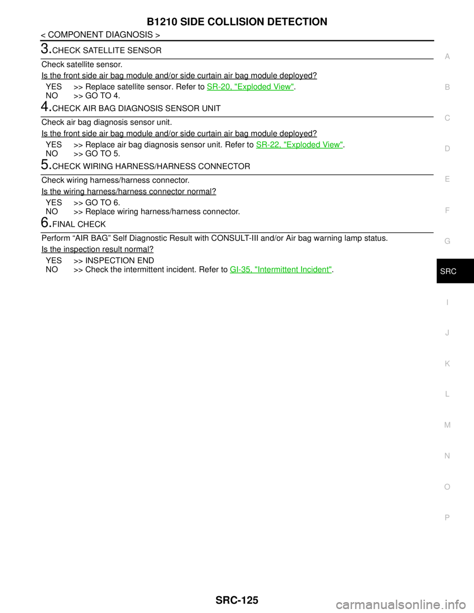
3.CHECK SATELLITE SENSOR
Check satellite sensor.
Is the front side air bag module and/or side curtain air bag module deployed?
YES >> Replace satellite sensor. Refer to SR-20, "Exploded View".
NO >> GO TO 4.
4.CHECK AIR BAG DIAGNOSIS SENSOR UNIT
Check air bag diagnosis sensor unit.
Is the front side air bag module and/or side curtain air bag module deployed?
YES >> Replace air bag diagnosis sensor unit. Refer to SR-22, "Exploded View".
NO >> GO TO 5.
5.CHECK WIRING HARNESS/HARNESS CONNECTOR
Check wiring harness/harness connector.
Is the wiring harness/harness connector normal?
YES >> GO TO 6.
NO >> Replace wiring harness/harness connector.
6.FINAL CHECK
Perform “AIR BAG” Self Diagnostic Result with CONSULT-III and/or Air bag warning lamp status.
Is the inspection result normal?
YES >> INSPECTION END
NO >> Check the intermittent incident. Refer to GI-35, "
Intermittent Incident".
Page 4369 of 5121

SRC-126
< COMPONENT DIAGNOSIS >
B1212, B1213, B1214 RH1 SAT-SENS
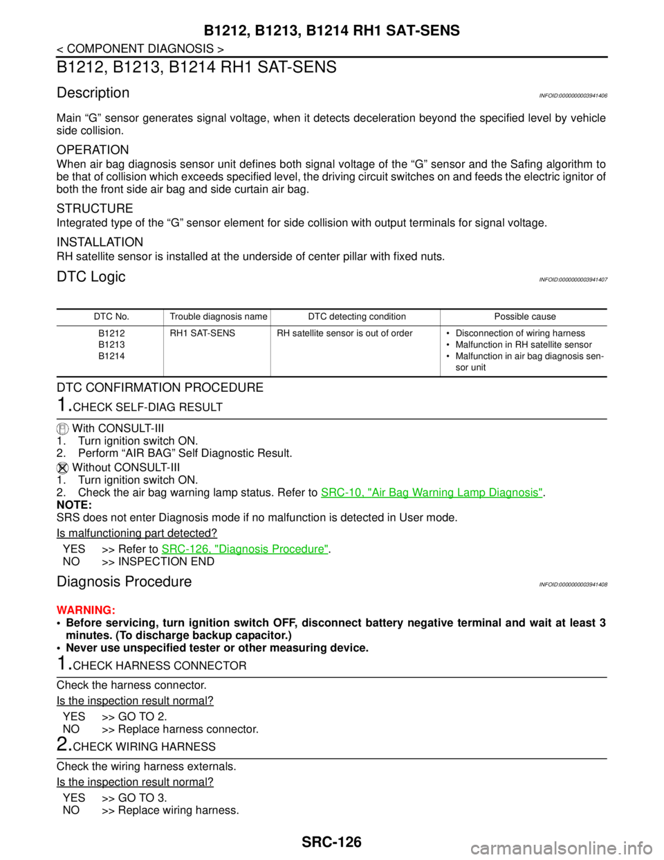
B1212, B1213, B1214 RH1 SAT-SENS
DescriptionINFOID:0000000003941406
Main “G” sensor generates signal voltage, when it detects deceleration beyond the specified level by vehicle
side collision.
OPERATION
When air bag diagnosis sensor unit defines both signal voltage of the “G” sensor and the Safing algorithm to
be that of collision which exceeds specified level, the driving circuit switches on and feeds the electric ignitor of
both the front side air bag and side curtain air bag.
STRUCTURE
Integrated type of the “G” sensor element for side collision with output terminals for signal voltage.
INSTALLATION
RH satellite sensor is installed at the underside of center pillar with fixed nuts.
DTC LogicINFOID:0000000003941407
DTC CONFIRMATION PROCEDURE
1.CHECK SELF-DIAG RESULT
With CONSULT-III
1. Turn ignition switch ON.
2. Perform “AIR BAG” Self Diagnostic Result.
Without CONSULT-III
1. Turn ignition switch ON.
2. Check the air bag warning lamp status. Refer to SRC-10, "
Air Bag Warning Lamp Diagnosis".
NOTE:
SRS does not enter Diagnosis mode if no malfunction is detected in User mode.
Is malfunctioning part detected?
YES >> Refer to SRC-126, "Diagnosis Procedure".
NO >> INSPECTION END
Diagnosis ProcedureINFOID:0000000003941408
WARNING:
Before servicing, turn ignition switch OFF, disconnect battery negative terminal and wait at least 3
minutes. (To discharge backup capacitor.)
Never use unspecified tester or other measuring device.
1.CHECK HARNESS CONNECTOR
Check the harness connector.
Is the inspection result normal?
YES >> GO TO 2.
NO >> Replace harness connector.
2.CHECK WIRING HARNESS
Check the wiring harness externals.
Is the inspection result normal?
YES >> GO TO 3.
NO >> Replace wiring harness.
DTC No. Trouble diagnosis name DTC detecting condition Possible cause
B1212
B1213
B1214RH1 SAT-SENS RH satellite sensor is out of order Disconnection of wiring harness
Malfunction in RH satellite sensor
Malfunction in air bag diagnosis sen-
sor unit
Page 4370 of 5121
B1212, B1213, B1214 RH1 SAT-SENS
SRC-127
< COMPONENT DIAGNOSIS >
C
D
E
F
G
I
J
K
L
MA
B
SRC
N
O
P
3.REPLACE SATELLITE SENSOR
1. Replace RH satellite sensor. Refer to SR-20, "
Exploded View".
2. Perform DTC confirmation procedure. Refer to SRC-126, "
DTC Logic".
Is DTC detected?
YES >> GO TO 4.
NO >> INSPECTION END
4.REPLACE AIR BAG DIAGNOSIS SENSOR UNIT
1. Replace air bag diagnosis sensor unit. Refer to SR-22, "
Exploded View".
2. Perform DTC confirmation procedure. Refer to SRC-126, "
DTC Logic".
Is DTC detected?
YES >> GO TO 1.
NO >> INSPECTION END
Page 4371 of 5121

SRC-128
< COMPONENT DIAGNOSIS >
B1215, B1216, B1217 LH1 SAT-SENS
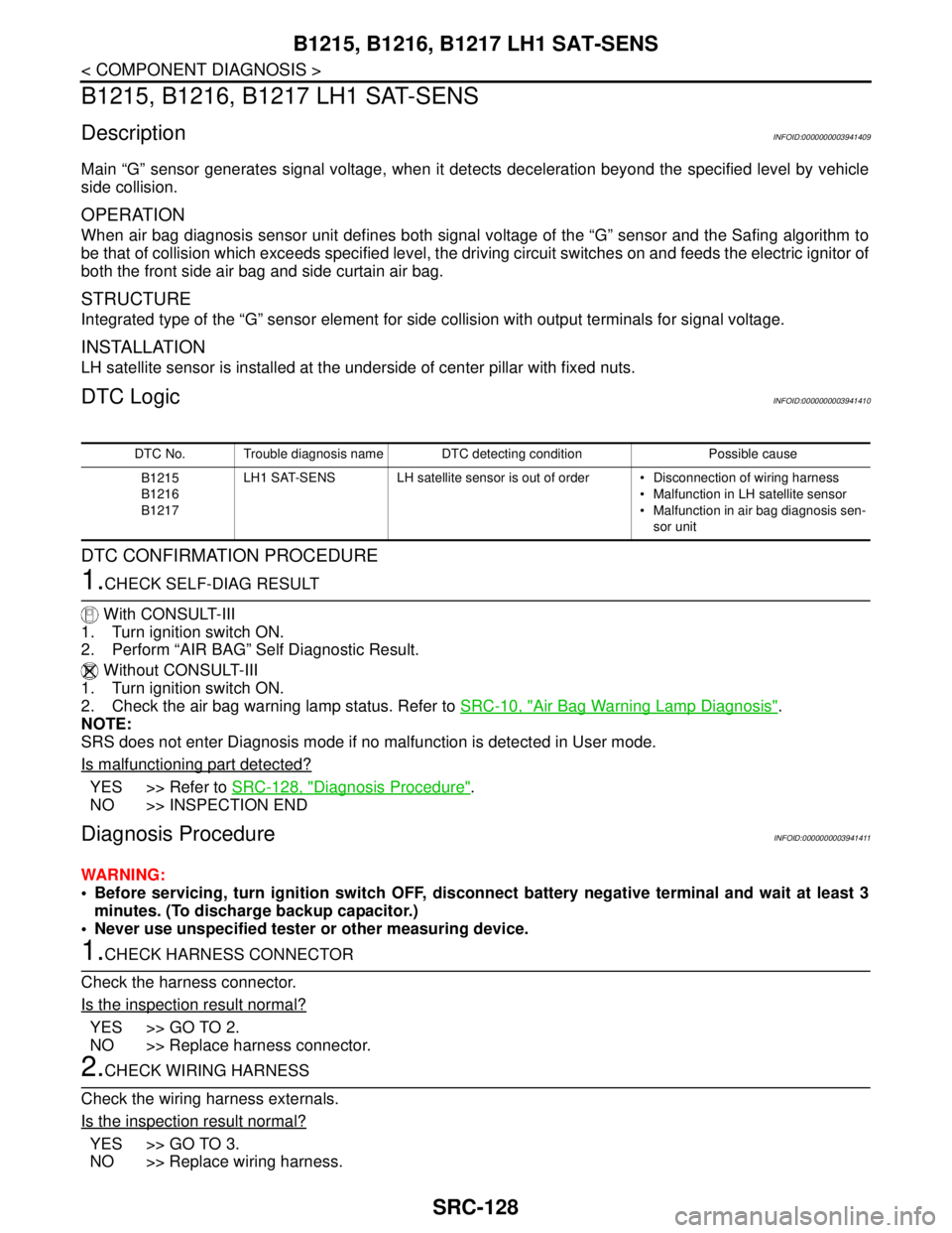
B1215, B1216, B1217 LH1 SAT-SENS
DescriptionINFOID:0000000003941409
Main “G” sensor generates signal voltage, when it detects deceleration beyond the specified level by vehicle
side collision.
OPERATION
When air bag diagnosis sensor unit defines both signal voltage of the “G” sensor and the Safing algorithm to
be that of collision which exceeds specified level, the driving circuit switches on and feeds the electric ignitor of
both the front side air bag and side curtain air bag.
STRUCTURE
Integrated type of the “G” sensor element for side collision with output terminals for signal voltage.
INSTALLATION
LH satellite sensor is installed at the underside of center pillar with fixed nuts.
DTC LogicINFOID:0000000003941410
DTC CONFIRMATION PROCEDURE
1.CHECK SELF-DIAG RESULT
With CONSULT-III
1. Turn ignition switch ON.
2. Perform “AIR BAG” Self Diagnostic Result.
Without CONSULT-III
1. Turn ignition switch ON.
2. Check the air bag warning lamp status. Refer to SRC-10, "
Air Bag Warning Lamp Diagnosis".
NOTE:
SRS does not enter Diagnosis mode if no malfunction is detected in User mode.
Is malfunctioning part detected?
YES >> Refer to SRC-128, "Diagnosis Procedure".
NO >> INSPECTION END
Diagnosis ProcedureINFOID:0000000003941411
WARNING:
Before servicing, turn ignition switch OFF, disconnect battery negative terminal and wait at least 3
minutes. (To discharge backup capacitor.)
Never use unspecified tester or other measuring device.
1.CHECK HARNESS CONNECTOR
Check the harness connector.
Is the inspection result normal?
YES >> GO TO 2.
NO >> Replace harness connector.
2.CHECK WIRING HARNESS
Check the wiring harness externals.
Is the inspection result normal?
YES >> GO TO 3.
NO >> Replace wiring harness.
DTC No. Trouble diagnosis name DTC detecting condition Possible cause
B1215
B1216
B1217LH1 SAT-SENS LH satellite sensor is out of order Disconnection of wiring harness
Malfunction in LH satellite sensor
Malfunction in air bag diagnosis sen-
sor unit
Page 4372 of 5121
B1215, B1216, B1217 LH1 SAT-SENS
SRC-129
< COMPONENT DIAGNOSIS >
C
D
E
F
G
I
J
K
L
MA
B
SRC
N
O
P
3.REPLACE SATELLITE SENSOR
1. Replace LH satellite sensor. Refer to SR-20, "
Exploded View".
2. Perform DTC confirmation procedure. Refer to SRC-128, "
DTC Logic"
Is DTC detected?
YES >> GO TO 4.
NO >> INSPECTION END
4.REPLACE AIR BAG DIAGNOSIS SENSOR UNIT
1. Replace air bag diagnosis sensor unit. Refer to SR-22, "
Exploded View".
2. Perform DTC confirmation procedure. Refer to SRC-128, "
DTC Logic".
Is DTC detected?
YES >> GO TO 1.
NO >> INSPECTION END
Page 4373 of 5121

SRC-130
< COMPONENT DIAGNOSIS >
B1218, B1219, B1220, B1221, B1222, B1223 CONTROL UNIT
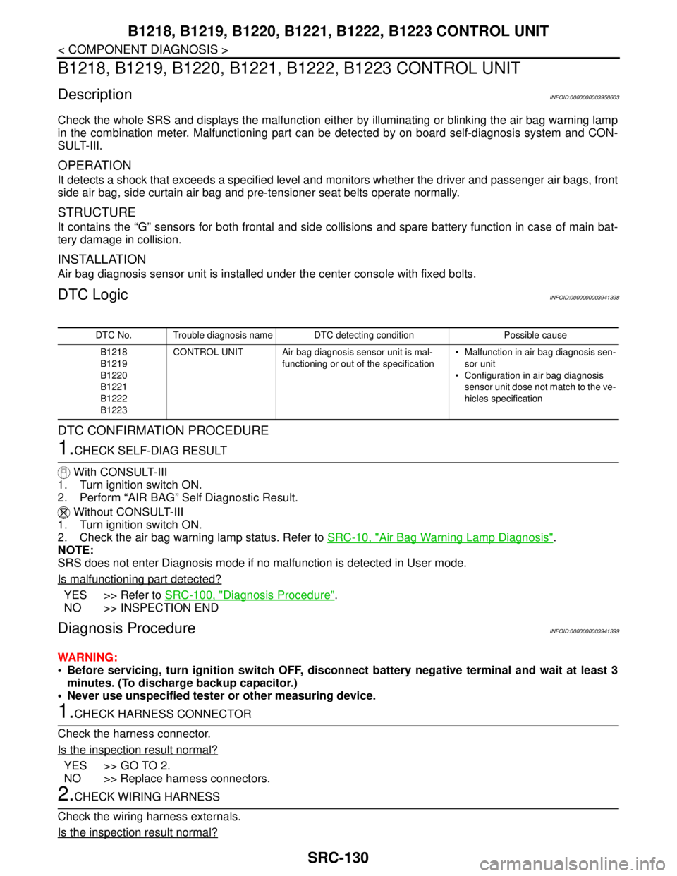
B1218, B1219, B1220, B1221, B1222, B1223 CONTROL UNIT
DescriptionINFOID:0000000003958603
Check the whole SRS and displays the malfunction either by illuminating or blinking the air bag warning lamp
in the combination meter. Malfunctioning part can be detected by on board self-diagnosis system and CON-
SULT-III.
OPERATION
It detects a shock that exceeds a specified level and monitors whether the driver and passenger air bags, front
side air bag, side curtain air bag and pre-tensioner seat belts operate normally.
STRUCTURE
It contains the “G” sensors for both frontal and side collisions and spare battery function in case of main bat-
tery damage in collision.
INSTALLATION
Air bag diagnosis sensor unit is installed under the center console with fixed bolts.
DTC LogicINFOID:0000000003941398
DTC CONFIRMATION PROCEDURE
1.CHECK SELF-DIAG RESULT
With CONSULT-III
1. Turn ignition switch ON.
2. Perform “AIR BAG” Self Diagnostic Result.
Without CONSULT-III
1. Turn ignition switch ON.
2. Check the air bag warning lamp status. Refer to SRC-10, "
Air Bag Warning Lamp Diagnosis".
NOTE:
SRS does not enter Diagnosis mode if no malfunction is detected in User mode.
Is malfunctioning part detected?
YES >> Refer to SRC-100, "Diagnosis Procedure".
NO >> INSPECTION END
Diagnosis ProcedureINFOID:0000000003941399
WARNING:
Before servicing, turn ignition switch OFF, disconnect battery negative terminal and wait at least 3
minutes. (To discharge backup capacitor.)
Never use unspecified tester or other measuring device.
1.CHECK HARNESS CONNECTOR
Check the harness connector.
Is the inspection result normal?
YES >> GO TO 2.
NO >> Replace harness connectors.
2.CHECK WIRING HARNESS
Check the wiring harness externals.
Is the inspection result normal?
DTC No. Trouble diagnosis name DTC detecting condition Possible cause
B1218
B1219
B1220
B1221
B1222
B1223CONTROL UNIT Air bag diagnosis sensor unit is mal-
functioning or out of the specification Malfunction in air bag diagnosis sen-
sor unit
Configuration in air bag diagnosis
sensor unit dose not match to the ve-
hicles specification
Page 4374 of 5121
B1218, B1219, B1220, B1221, B1222, B1223 CONTROL UNIT
SRC-131
< COMPONENT DIAGNOSIS >
C
D
E
F
G
I
J
K
L
MA
B
SRC
N
O
P
YES >> GO TO 3.
NO >> Replace wiring harness.
3.REPLACE AIR BAG DIAGNOSIS SENSOR UNIT
1. Replace air bag diagnosis sensor unit. Refer to SR-22, "
Exploded View".
2. Perform DTC confirmation procedure. Refer to SRC-100, "
DTC Logic".
Is DTC detected?
YES >> GO TO 1.
NO >> INSPECTION END
Page 4375 of 5121
![NISSAN TEANA 2008 Service Manual SRC-132
< ECU DIAGNOSIS >
DIAGNOSIS SENSOR UNIT
ECU DIAGNOSIS
DIAGNOSIS SENSOR UNIT
DTC IndexINFOID:0000000003814104
DTC No. Index (With CONSULT-III)
(“SELF-DIAG [CURRENT]”), (“SELF-DIAG [PAST]� NISSAN TEANA 2008 Service Manual SRC-132
< ECU DIAGNOSIS >
DIAGNOSIS SENSOR UNIT
ECU DIAGNOSIS
DIAGNOSIS SENSOR UNIT
DTC IndexINFOID:0000000003814104
DTC No. Index (With CONSULT-III)
(“SELF-DIAG [CURRENT]”), (“SELF-DIAG [PAST]�](/manual-img/5/57391/w960_57391-4374.png)
SRC-132
< ECU DIAGNOSIS >
DIAGNOSIS SENSOR UNIT
ECU DIAGNOSIS
DIAGNOSIS SENSOR UNIT
DTC IndexINFOID:0000000003814104
DTC No. Index (With CONSULT-III)
(“SELF-DIAG [CURRENT]”), (“SELF-DIAG [PAST]” or “TROUBLE DIAG RECORD”)
NOTE:
Follow the procedures in numerical order when repairing malfunctioning parts. Confirm whether malfunction is
eliminated using air bag warning lamp or CONSULT-III each time repair is completed. If malfunction is still
observed, proceed to the next step. When malfunction is eliminated, further repair work is not required.
Diagnostic item ExplanationRepair order
“Recheck SRS at each replacement”
NO DTC IS DETECT-
ED.When malfunction is in-
dicated by the “AIR
BAG” warning lamp in
User modeLow battery voltage (Less than 9 V)
Self-diagnosis result “SELF-DIAG
[PAST]” (previously stored in the
memory) might not be erased after re-
pair
Intermittent malfunction has been de-
tected in the pastGo to SRC-10, "
Air Bag Warning Lamp
Diagnosis" or SRC-15, "CONSULT-III
Function"
No malfunction is detected —
CONTROL UNIT
[B1001-B1015]Air bag diagnosis sensor unit is out of order or mis-matched Replace air bag diagnosis sensor unit
CONTROL UNIT
[B1026-B1031]Air bag diagnosis sensor unit is out of order or mis-matched Replace air bag diagnosis sensor unit
CRASH ZONE SEN
[UNIT FAIL]
[B1033]
[B1034]
CRASH ZONE SEN
[COMM FAIL]
[B1035]
[UNMATCH]
[B1036]
CRASH ZONE SEN1
[B1037]
[B1039]
[B1041]Crash zone sensor is out of order 1. Replace wiring harness/harness
connector
2. Replace crash zone sensor
3. Replace air bag diagnosis sensor
unit
CONTROL UNIT
[B1042-B1047]Air bag diagnosis sensor unit is out of order or mis-matched Replace air bag diagnosis sensor unit
DRIVER AIRBAG MOD-
ULE
[OPEN]
[B1049]Driver air bag module circuit is open (including the spiral cable) 1. Replace wiring harness/harness
connector
2. Replace driver air bag module
3. Replace spiral cable.
4. Replace air bag diagnosis sensor
unit DRIVER AIRBAG MOD-
ULE
[VB-SHORT]
[B1050]Driver air bag module circuit is shorted to some power supply cir-
cuit (including the spiral cable)
DRIVER AIRBAG MOD-
ULE
[GND-SHORT]
[B1051]Driver air bag module circuit is shorted to ground (including the spi-
ral cable)
DRIVER AIRBAG MOD-
ULE
[SHORT]
[B1052]Driver air bag module circuits are shorted to each other (including
spiral cable)