Page 1492 of 3000
AX–126U151E AUTOMATIC TRANSAXLE – AUTOMATIC TRANSAXLE SYSTEM
AX
(a) Remove the shift solenoid valve (SLT).
(b) Measure the resistance according to the value(s) in the
table below.
Standard resistance
(c) Connect the positive (+) lead with a 21 W bulb to
terminal 2 and the negative (-) lead to terminal 1 of the
solenoid valve connector, then check the movement of
the valve.
OK:
The solenoid makes an operating sound.
NG
OK
3INSPECT SHIFT SOLENOID VALVE SLT
G020767E82
Tester ConnectionSpecified Condition
20C (68F)
1 - 2 5.0 to 5.6
REPLACE SHIFT SOLENOID VALVE SLT
REPAIR OR REPLACE TRANSMISSION WIRE
Page 1493 of 3000

U151E AUTOMATIC TRANSAXLE – AUTOMATIC TRANSAXLE SYSTEMAX–127
AX
DESCRIPTION
The shift solenoid valve DSL is turned "ON" and "OFF" by signals from the ECM in order to control the
hydraulic pressure operation, the lock-up relay valve, which then controls operation of the lock-up clutch.
MONITOR DESCRIPTION
Torque converter lock-up is controlled by the ECM based on engine rpm, engine load, engine
temperature, vehicle speed, transmission temperature, and shift range selection. The ECM determines
the lock-up status of the torque converter by comparing the engine rpm (NE) to the input turbine rpm (NT).
The ECM calculates the actual transmission gear by comparing input turbine rpm (NT) to counter gear
rpm (NC). When conditions are appropriate, the ECM requests "lock-up" by applying control voltage to the
shift solenoid DSL. When the DSL is opened, it applies pressure to the lock-up relay valve and locks the
torque converter clutch. If the ECM detects an open or short in the DSL solenoid circuit, the ECM
interprets this as a fault in the DSL solenoid or circuit. The ECM will turn on the MIL and store the DTC.
MONITOR STRATEGY
TYPICAL ENABLING CONDITIONS
P2769: Range check (Low resistance):
P2770: Range check (High resistance):
DTC P2769Torque Converter Clutch Solenoid Circuit Low
(Shift Solenoid Valve DSL)
DTC P2770Torque Converter Clutch Solenoid Circuit High
(Shift Solenoid Valve DSL)
DTC No. DTC Detection Condition Trouble Area
P2769ECM detects short in solenoid valve DSL circuit (0.1
sec.) when solenoid valve DSL is operated (2-trip
detection logic)• Short in shift solenoid valve DSL circuit
• Shift solenoid valve DSL
•ECM
P2770ECM detects open in solenoid valve DSL circuit (0.1
sec.) when solenoid valve DSL is not operated (2-trip
detection logic)• Open in shift solenoid valve DSL circuit
• Shift solenoid valve DSL
•ECM
Related DTCsP2769: Shift solenoid valve DSL/Range check (Low resistance)
P2770: Shift solenoid valve DSL/Range check (High resistance)
Required sensors/Components Shift solenoid valve DSL
Frequency of operation Continuous
Duration 0.064 sec. or more
MIL operation 2 driving cycles
Sequence of operation None
The monitor will run whenever this DTC is not present. None
Shift solenoid valve DSLON
Solenoid current cut status Not cut
Battery voltage8 V or more
Ignition switchON
Sta r t e rOFF
The monitor will run whenever this DTC is not present. None
Shift solenoid valve DSLON
Battery voltage8 V or more
Ignition switchON
Page 1494 of 3000
AX–128U151E AUTOMATIC TRANSAXLE – AUTOMATIC TRANSAXLE SYSTEM
AX
TYPICAL MALFUNCTION THRESHOLDS
P2769: Range check (Low resistance):
P2770: Range check (High resistance):
COMPONENT OPERATING RANGE
WIRING DIAGRAM
INSPECTION PROCEDURE
(a) Disconnect the transmission wire connector from the
transaxle.
(b) Measure the resistance according to the value(s) in the
table below.
Standard resistance
NG
StarterOFF
Shift solenoid valve DSL resistance 8
or less
Shift solenoid valve DSL resistance 100 k
or more
Shift solenoid valve DSL Resistance: 11 to 13
at 20C (68F)
1INSPECT TRANSMISSION WIRE (DSL)
G031165E84
C113969E11
Tester ConnectionSpecified Condition
20C (68F)
10 (DSL) - Body ground 11 to 13
Go to step 3
Page 1495 of 3000
U151E AUTOMATIC TRANSAXLE – AUTOMATIC TRANSAXLE SYSTEMAX–129
AX
OK
(a) Connect the transmission wire connector.
(b) Disconnect the ECM connector.
(c) Measure the resistance according to the value(s) in the
table below.
Standard resistance
NG
OK
(a) Remove the shift solenoid valve DSL.
(b) Measure the resistance according to the value(s) in the
table below.
Standard resistance
(c) Connect the positive (+) lead to the terminal of the
solenoid connector, and the negative (-) lead to the
solenoid body.
OK:
The solenoid valve makes an operating sound.
NG
OK
2CHECK HARNESS AND CONNECTOR (TRANSMISSION WIRE - ECM)
C160512E08
Tester ConnectionSpecified Condition
20C (68F)
E10-11 (DSL) - Body ground 11 to 13
REPAIR OR REPLACE HARNESS OR
CONNECTOR
REPLACE ECM
3INSPECT SHIFT SOLENOID VALVE DSL
C113970E08
Tester ConnectionSpecified Condition
20C (68F)
Solenoid Connector (DSL) - Solenoid
Body (DSL)11 to 13
REPLACE SHIFT SOLENOID VALVE DSL
REPAIR OR REPLACE TRANSMISSION WIRE
Page 1503 of 3000

AX–16U151E AUTOMATIC TRANSAXLE – AUTOMATIC TRANSAXLE SYSTEM
AX
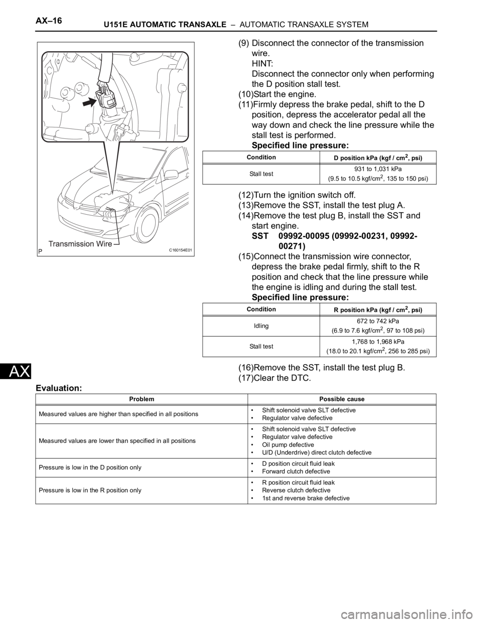
(9) Disconnect the connector of the transmission
wire.
HINT:
Disconnect the connector only when performing
the D position stall test.
(10)Start the engine.
(11)Firmly depress the brake pedal, shift to the D
position, depress the accelerator pedal all the
way down and check the line pressure while the
stall test is performed.
Specified line pressure:
(12)Turn the ignition switch off.
(13)Remove the SST, install the test plug A.
(14)Remove the test plug B, install the SST and
start engine.
SST 09992-00095 (09992-00231, 09992-
00271)
(15)Connect the transmission wire connector,
depress the brake pedal firmly, shift to the R
position and check that the line pressure while
the engine is idling and during the stall test.
Specified line pressure:
(16)Remove the SST, install the test plug B.
(17)Clear the DTC.
Evaluation:
C160154E01
Condition
D position kPa (kgf / cm2, psi)
Stall test931 to 1,031 kPa
(9.5 to 10.5 kgf/cm
2, 135 to 150 psi)
Condition
R position kPa (kgf / cm
2, psi)
Idling672 to 742 kPa
(6.9 to 7.6 kgf/cm
2, 97 to 108 psi)
Stall test1,768 to 1,968 kPa
(18.0 to 20.1 kgf/cm
2, 256 to 285 psi)
Problem Possible cause
Measured values are higher than specified in all positions• Shift solenoid valve SLT defective
• Regulator valve defective
Measured values are lower than specified in all positions• Shift solenoid valve SLT defective
• Regulator valve defective
• Oil pump defective
• U/D (Underdrive) direct clutch defective
Pressure is low in the D position only• D position circuit fluid leak
• Forward clutch defective
Pressure is low in the R position only• R position circuit fluid leak
• Reverse clutch defective
• 1st and reverse brake defective
Page 1514 of 3000

U151E AUTOMATIC TRANSAXLE – TRANSMISSION WIREAX–131
AX
REMOVAL
1. DISCONNECT CABLE FROM NEGATIVE BATTERY
TERMINAL
2. REMOVE ENGINE UNDER COVER NO.1
3. DRAIN AUTOMATIC TRANSAXLE FLUID
(a) Remove the drain plug and gasket, and drain the
AT F.
(b) Install a new gasket and the drain plug.
Torque: 49 N*m (500 kgf*cm, 36 ft.*lbf)
4. REMOVE AUTOMATIC TRANSAXLE OIL PAN SUB-
ASSEMBLY
(a) Remove the 18 bolts, oil pan and gasket.
NOTICE:
Some fluid will remain in the oil pan. Carefully
remove the oil pan so that fluid remaining in the
pan does not spill out.
(b) Remove the 2 magnets from the oil pan.
(c) Examine particles in the pan.
(1) Collect any steel chips using the removed
magnets. Look carefully at the chips and
particles in the pan and on the magnets to see
the type of wear which might be found in the
transaxle.
Result:
Steel (magnetic):
Wear of the bearing, gear or plate
Brass (non-magnetic):
Wear of the bearing
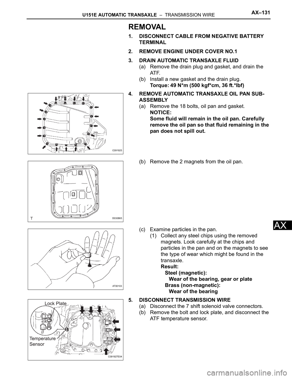
5. DISCONNECT TRANSMISSION WIRE
(a) Disconnect the 7 shift solenoid valve connectors.
(b) Remove the bolt and lock plate, and disconnect the
ATF temperature sensor.
C091925
D030865
AT00103
C091927E04
Page 1515 of 3000
AX–132U151E AUTOMATIC TRANSAXLE – TRANSMISSION WIRE
AX
6. REMOVE TRANSMISSION WIRE
(a) Disconnect the transmission wire connector.
(b) Remove the bolt and transmission wire.
(c) Remove the O-ring from the transmission wire.
INSTALLATION
1. INSTALL TRANSMISSION WIRE
(a) Coat the O-ring of the transmission wire connector
with ATF and install it.
(b) Install the transmission wire with the bolt.
Torque: 5.4 N*m (55 kgf*cm, 48 ft.*lbf)
2. CONNECT TRANSMISSION WIRE
(a) Coat the O-ring of the ATF temperature sensor with
AT F.
(b) Install the ATF temperature sensor with the lock
plate and bolt.
Torque: 6.6 N*m (67 kgf*cm, 58 ft.*lbf)
(c) Connect the 7 shift solenoid valve connectors.
3. INSTALL AUTOMATIC TRANSAXLE OIL PAN SUB-
ASSEMBLY
(a) Install the 2 magnets in the oil pan.
(b) Apply seal packing to the 18 bolts.
Seal packing:
THREE BOND 2430 or equivalent
D030866
D030867
D030866
C091927E04
D030865
Page 1519 of 3000

AX–136U151E AUTOMATIC TRANSAXLE – VALVE BODY ASSEMBLY
AX
REMOVAL
1. REMOVE ENGINE UNDER COVER NO.1
2. DISCONNECT CABLE FROM NEGATIVE BATTERY
TERMINAL
3. DRAIN AUTOMATIC TRANSAXLE FLUID (See page
AX-131)
4. REMOVE AUTOMATIC TRANSAXLE OIL PAN SUB-
ASSEMBLY
(a) Remove the 18 bolts, oil pan and gasket.
NOTICE:
Some fluid will remain in the oil pan. Carefully
remove the oil pan so that the fluid remaining in
the pan does not spill out.
(b) Remove the 2 magnets from the oil pan.
(c) Examine particles in the pan.
(1) Collect any steel chips using the removed
magnets. Look carefully at the chips and
particles in the pan and on the magnets to see
the type of wear which might be found in the
transaxle.
Result:
Steel (magnetic):
Wear of the bearing, gear or plate
Brass (non-magnetic):
Wear of the bearing
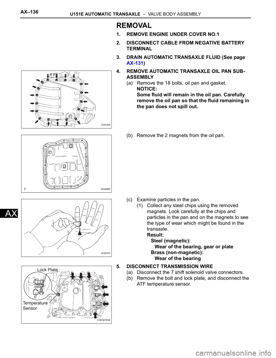
5. DISCONNECT TRANSMISSION WIRE
(a) Disconnect the 7 shift solenoid valve connectors.
(b) Remove the bolt and lock plate, and disconnect the
ATF temperature sensor.
C091925
D030865
AT00103
C091927E04