Page 1797 of 3000
U151F AUTOMATIC TRANSAXLE – AUTOMATIC TRANSAXLE SYSTEMAX–125
AX
INSPECTION PROCEDURE
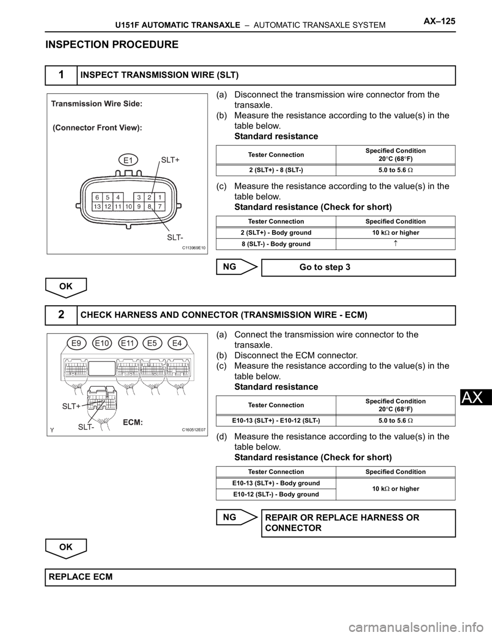
(a) Disconnect the transmission wire connector from the
transaxle.
(b) Measure the resistance according to the value(s) in the
table below.
Standard resistance
(c) Measure the resistance according to the value(s) in the
table below.
Standard resistance (Check for short)
NG
OK
(a) Connect the transmission wire connector to the
transaxle.
(b) Disconnect the ECM connector.
(c) Measure the resistance according to the value(s) in the
table below.
Standard resistance
(d) Measure the resistance according to the value(s) in the
table below.
Standard resistance (Check for short)
NG
OK
1INSPECT TRANSMISSION WIRE (SLT)
C113969E10
Tester ConnectionSpecified Condition
20C (68F)
2 (SLT+) - 8 (SLT-) 5.0 to 5.6
Tester Connection Specified Condition
2 (SLT+) - Body ground 10 k
or higher
8 (SLT-) - Body ground
Go to step 3
2CHECK HARNESS AND CONNECTOR (TRANSMISSION WIRE - ECM)
C160512E07
Tester ConnectionSpecified Condition
20C (68F)
E10-13 (SLT+) - E10-12 (SLT-) 5.0 to 5.6
Tester Connection Specified Condition
E10-13 (SLT+) - Body ground
10 k
or higher
E10-12 (SLT-) - Body ground
REPAIR OR REPLACE HARNESS OR
CONNECTOR
REPLACE ECM
Page 1801 of 3000
U151F AUTOMATIC TRANSAXLE – AUTOMATIC TRANSAXLE SYSTEMAX–129
AX
OK
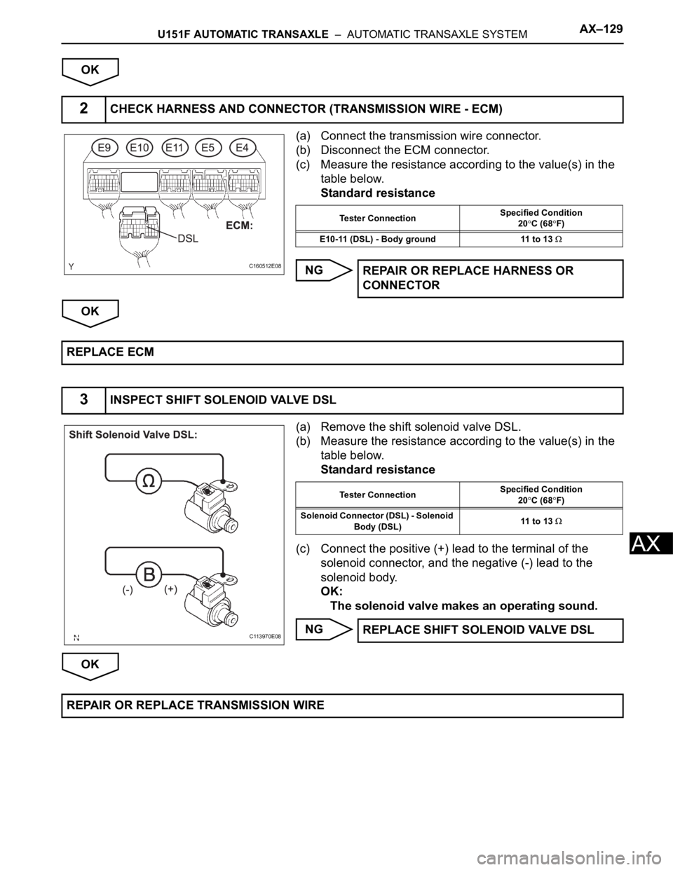
(a) Connect the transmission wire connector.
(b) Disconnect the ECM connector.
(c) Measure the resistance according to the value(s) in the
table below.
Standard resistance
NG
OK
(a) Remove the shift solenoid valve DSL.
(b) Measure the resistance according to the value(s) in the
table below.
Standard resistance
(c) Connect the positive (+) lead to the terminal of the
solenoid connector, and the negative (-) lead to the
solenoid body.
OK:
The solenoid valve makes an operating sound.
NG
OK
2CHECK HARNESS AND CONNECTOR (TRANSMISSION WIRE - ECM)
C160512E08
Tester ConnectionSpecified Condition
20C (68F)
E10-11 (DSL) - Body ground 11 to 13
REPAIR OR REPLACE HARNESS OR
CONNECTOR
REPLACE ECM
3INSPECT SHIFT SOLENOID VALVE DSL
C113970E08
Tester ConnectionSpecified Condition
20C (68F)
Solenoid Connector (DSL) - Solenoid
Body (DSL)11 to 13
REPLACE SHIFT SOLENOID VALVE DSL
REPAIR OR REPLACE TRANSMISSION WIRE
Page 1880 of 3000
AX–164U151F AUTOMATIC TRANSAXLE – AUTOMATIC TRANSAXLE ASSEMBLY
AX
REMOVAL
1. REMOVE ENGINE ASSEMBLY WITH TRANSAXLE
HINT:
(See page EM-26)
2. REMOVE FRONT DRIVE SHAFT ASSEMBLY LH
HINT:
(See page DS-6)
3. REMOVE FRONT DRIVE SHAFT ASSEMBLY RH
HINT:
(See page DS-7)
4. REMOVE TRANSMISSION CONTROL CABLE CLAMP
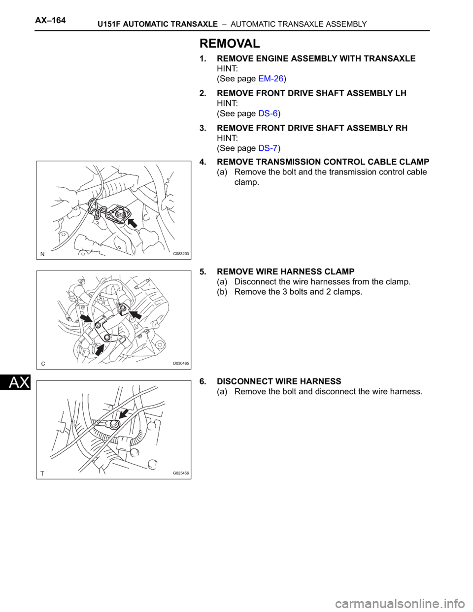
(a) Remove the bolt and the transmission control cable
clamp.
5. REMOVE WIRE HARNESS CLAMP
(a) Disconnect the wire harnesses from the clamp.
(b) Remove the 3 bolts and 2 clamps.
6. DISCONNECT WIRE HARNESS
(a) Remove the bolt and disconnect the wire harness.
C083203
D030465
G025456
Page 1881 of 3000
U151F AUTOMATIC TRANSAXLE – AUTOMATIC TRANSAXLE ASSEMBLYAX–165
AX
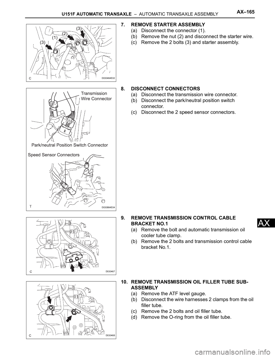
7. REMOVE STARTER ASSEMBLY
(a) Disconnect the connector (1).
(b) Remove the nut (2) and disconnect the starter wire.
(c) Remove the 2 bolts (3) and starter assembly.
8. DISCONNECT CONNECTORS
(a) Disconnect the transmission wire connector.
(b) Disconnect the park/neutral position switch
connector.
(c) Disconnect the 2 speed sensor connectors.
9. REMOVE TRANSMISSION CONTROL CABLE
BRACKET NO.1
(a) Remove the bolt and automatic transmission oil
cooler tube clamp.
(b) Remove the 2 bolts and transmission control cable
bracket No.1.
10. REMOVE TRANSMISSION OIL FILLER TUBE SUB-
ASSEMBLY
(a) Remove the ATF level gauge.
(b) Disconnect the wire harnesses 2 clamps from the oil
filler tube.
(c) Remove the 2 bolts and oil filler tube.
(d) Remove the O-ring from the oil filler tube.
D030464E02
D030864E04
D030467
D030468
Page 1887 of 3000
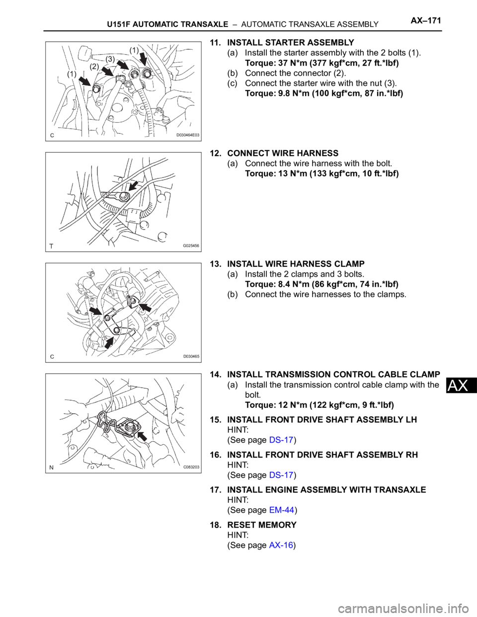
U151F AUTOMATIC TRANSAXLE – AUTOMATIC TRANSAXLE ASSEMBLYAX–171
AX
11. INSTALL STARTER ASSEMBLY
(a) Install the starter assembly with the 2 bolts (1).
Torque: 37 N*m (377 kgf*cm, 27 ft.*lbf)
(b) Connect the connector (2).
(c) Connect the starter wire with the nut (3).
Torque: 9.8 N*m (100 kgf*cm, 87 in.*lbf)
12. CONNECT WIRE HARNESS
(a) Connect the wire harness with the bolt.
Torque: 13 N*m (133 kgf*cm, 10 ft.*lbf)
13. INSTALL WIRE HARNESS CLAMP
(a) Install the 2 clamps and 3 bolts.
Torque: 8.4 N*m (86 kgf*cm, 74 in.*lbf)
(b) Connect the wire harnesses to the clamps.
14. INSTALL TRANSMISSION CONTROL CABLE CLAMP
(a) Install the transmission control cable clamp with the
bolt.
Torque: 12 N*m (122 kgf*cm, 9 ft.*lbf)
15. INSTALL FRONT DRIVE SHAFT ASSEMBLY LH
HINT:
(See page DS-17)
16. INSTALL FRONT DRIVE SHAFT ASSEMBLY RH
HINT:
(See page DS-17)
17. INSTALL ENGINE ASSEMBLY WITH TRANSAXLE
HINT:
(See page EM-44)
18. RESET MEMORY
HINT:
(See page AX-16)
D030464E03
G025456
D030465
C083203
Page 2287 of 3000

TIRE AND WHEEL – TIRE PRESSURE WARNING SYSTEMTW–45
TW
DESCRIPTION
The tire pressure warning valve and transmitters that are installed in the tire and wheel assemblies
measure the air pressure of the tires. The measured values are transmitted to the tire pressure warning
antenna and receiver on the body as radio waves and then sent to the tire pressure warning ECU. The
ECU compares the measured air pressure values with the air pressure threshold. When the measured air
pressure value is less than this threshold, the warning light in the combination meter comes on.
The tire pressure warning valve and transmitters constantly send radio waves to the tire pressure warning
antenna and receiver.
Under the following conditions below, the tire pressure warning antenna and receiver is unable to receive
the signals from the tire pressure warning valves and transmitters, and a DTC is stored.
• Facilities or devices that use similar radio frequencies are located in the vicinity of the vehicle.
• Devices using similar radio frequencies are used in the vehicle.
• The goods which obstruct the radio signal of the valve and transmitter, for example, tire chain or
window film.
HINT:
When no signals are received for 20 minutes or more, a DTC is output.
DTCs from C2121/21 to C2124/24 can only be cleared by using the tester. DTCs from C2181/81 to
C2184/84 can be cleared when the transmitter in the tire pressure warning valve and transmitter sends a
forced transmission signal or test mode ends. DTCs from C2181/81 to C2184/84 are output only in test
mode.
HINT:
It is necessary to perform the procedure to identify the tire pressure warning valve and transmitter that is
malfunctioning because it cannot be identified by the output DTC.
DTC C2121/21 No Signal from Transmitter ID1
DTC C2122/22 No Signal from Transmitter ID2
DTC C2123/23 No Signal from Transmitter ID3
DTC C2124/24 No Signal from Transmitter ID4
DTC C2181/81 Transmitter ID1 not Received (Test Mode DTC)
DTC C2182/82 Transmitter ID2 not Received (Test Mode DTC)
DTC C2183/83 Transmitter ID3 not Received (Test Mode DTC)
DTC C2184/84 Transmitter ID4 not Received (Test Mode DTC)
DTC No. DTC Detection Condition Trouble Area
C2121/21
C2122/22
C2123/23
C2124/24These DTCs are detected when no signals are received
for 20 minute drive or more.• Tire pressure warning valve and transmitter
• Tire pressure warning antenna and receiver
• Wire harness or connector
• Tire pressure warning ECU
C2181/81
C2182/82
C2183/83
C2184/84Malfunction in the transmitting/receiving circuit• Tire pressure warning valve and transmitter
• Tire pressure warning antenna and receiver
• Wire harness or connector
• Tire pressure warning ECU