Page 1717 of 3000

U151F AUTOMATIC TRANSAXLE – AUTOMATIC TRANSAXLE SYSTEMAX–45
AX
DESCRIPTION
The park/neutral position switch detects the shift lever position and sends signals to the ECM.
MONITOR DESCRIPTION
These DTCs indicate a problem with the park/neutral position switch and the wire harness in the park/
neutral position switch circuit.
The park/neutral position switch detects the shift lever position and sends a signal to the ECM.
For security, the park/neutral position switch detects the shift lever position so that engine can be started
only when the shift lever is in the P or N position
The park/neutral position switch sends a signal to the ECM according to the shift position (P, R, N or D).
The ECM determines that there is a problem with the switch or related parts if in receives more than 1
position signal simultaneously. The ECM will turn on the MIL and store the DTC.
MONITOR STRATEGY
DTC P0705Transmission Range Sensor Circuit Malfunc-
tion (PRNDL Input)
DTC No. DTC Detection Condition Trouble Area
P0705(A) Any 2 or more signals of the following are ON
simultaneously (2-trip detection logic)
• P input signal is ON.
• N input signal is ON.
• R input signal is ON.
• D input signal is ON.
• 3 input signal is ON.
• 2 input signal is ON.
(B) Any 2 or more signals of the following are ON
simultaneously (2-trip detection logic)
• NSW (STAR) input signal is ON.
• R input signal is ON.
• D input signal is ON.
• 3 input signal is ON.
• 2 input signal is ON.
(C) All switches are OFF simultaneously for
NSW(STAR), P, R, N, D, 3, 2 positions (2-trip detection
logic).
(D) Both 1 and 2 conditions are met (2-trip detection
logic)
1. One of the following conditions are met
(a) NSW (STAR) input signal is ON.
(b) P input signal is ON.
(c) N input signal is ON.
(d) R input signal is ON.
2. One of the following conditions are met
(a) 4 input signal is ON.
(b) L input signal is ON.• Short in park/neutral position switch circuit
• Park/neutral position switch
•ECM
Related DTCs P0705: Park/neutral position switch/Verify switch input
Required sensors/Components Park/neutral position switch
Frequency of operation Continuous
DurationCondition (A), (B), (D)
2 sec.
Condition (C)
60 sec.
MIL operation 2 driving cycles
Sequence of operation None
Page 1725 of 3000
U151F AUTOMATIC TRANSAXLE – AUTOMATIC TRANSAXLE SYSTEMAX–53
AX
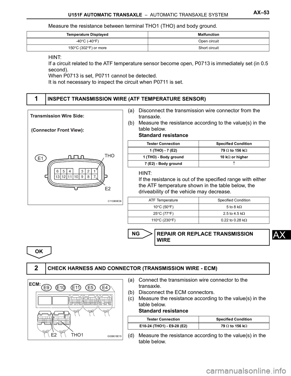
Measure the resistance between terminal THO1 (THO) and body ground.
HINT:
If a circuit related to the ATF temperature sensor become open, P0713 is immediately set (in 0.5
second).
When P0713 is set, P0711 cannot be detected.
It is not necessary to inspect the circuit when P0711 is set.
(a) Disconnect the transmission wire connector from the
transaxle.
(b) Measure the resistance according to the value(s) in the
table below.
Standard resistance
HINT:
If the resistance is out of the specified range with either
the ATF temperature shown in the table below, the
driveability of the vehicle may decrease.
NG
OK
(a) Connect the transmission wire connector to the
transaxle.
(b) Disconnect the ECM connectors.
(c) Measure the resistance according to the value(s) in the
table below.
Standard resistance
(d) Measure the resistance according to the value(s) in the
table below.
Temperature Displayed Malfunction
-40
C (-40F) Open circuit
150
C (302F) or more Short circuit
1INSPECT TRANSMISSION WIRE (ATF TEMPERATURE SENSOR)
C113969E36
Tester Connection Specified Condition
1 (THO) - 7 (E2) 79
to 156 k
1 (THO) - Body ground 10 k or higher
7 (E2) - Body ground
ATF Temperature Specified Condition
10
C (50F) 5 to 8 k
25C (77F) 2.5 to 4.5 k
11 0C (230F) 0.22 to 0.28 k
REPAIR OR REPLACE TRANSMISSION
WIRE
2CHECK HARNESS AND CONNECTOR (TRANSMISSION WIRE - ECM)
G038618E15
Tester Connection Specified Condition
E10-24 (THO1) - E9-28 (E2) 79
to 156 k
Page 1743 of 3000
U151F AUTOMATIC TRANSAXLE – AUTOMATIC TRANSAXLE SYSTEMAX–71
AX
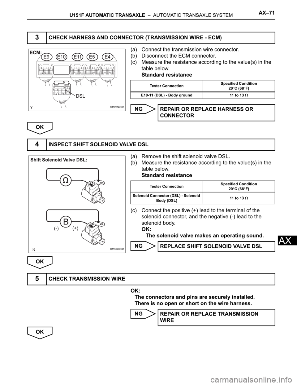
(a) Connect the transmission wire connector.
(b) Disconnect the ECM connector.
(c) Measure the resistance according to the value(s) in the
table below.
Standard resistance
NG
OK
(a) Remove the shift solenoid valve DSL.
(b) Measure the resistance according to the value(s) in the
table below.
Standard resistance
(c) Connect the positive (+) lead to the terminal of the
solenoid connector, and the negative (-) lead to the
solenoid body.
OK:
The solenoid valve makes an operating sound.
NG
OK
OK:
The connectors and pins are securely installed.
There is no open or short on the wire harness.
NG
OK
3CHECK HARNESS AND CONNECTOR (TRANSMISSION WIRE - ECM)
C152056E03
Tester ConnectionSpecified Condition
20C (68F)
E10-11 (DSL) - Body ground 11 to 13
REPAIR OR REPLACE HARNESS OR
CONNECTOR
4INSPECT SHIFT SOLENOID VALVE DSL
C113970E08
Tester ConnectionSpecified Condition
20C (68F)
Solenoid Connector (DSL) - Solenoid
Body (DSL)11 to 13
REPLACE SHIFT SOLENOID VALVE DSL
5CHECK TRANSMISSION WIRE
REPAIR OR REPLACE TRANSMISSION
WIRE
Page 1751 of 3000
U151F AUTOMATIC TRANSAXLE – AUTOMATIC TRANSAXLE SYSTEMAX–79
AX
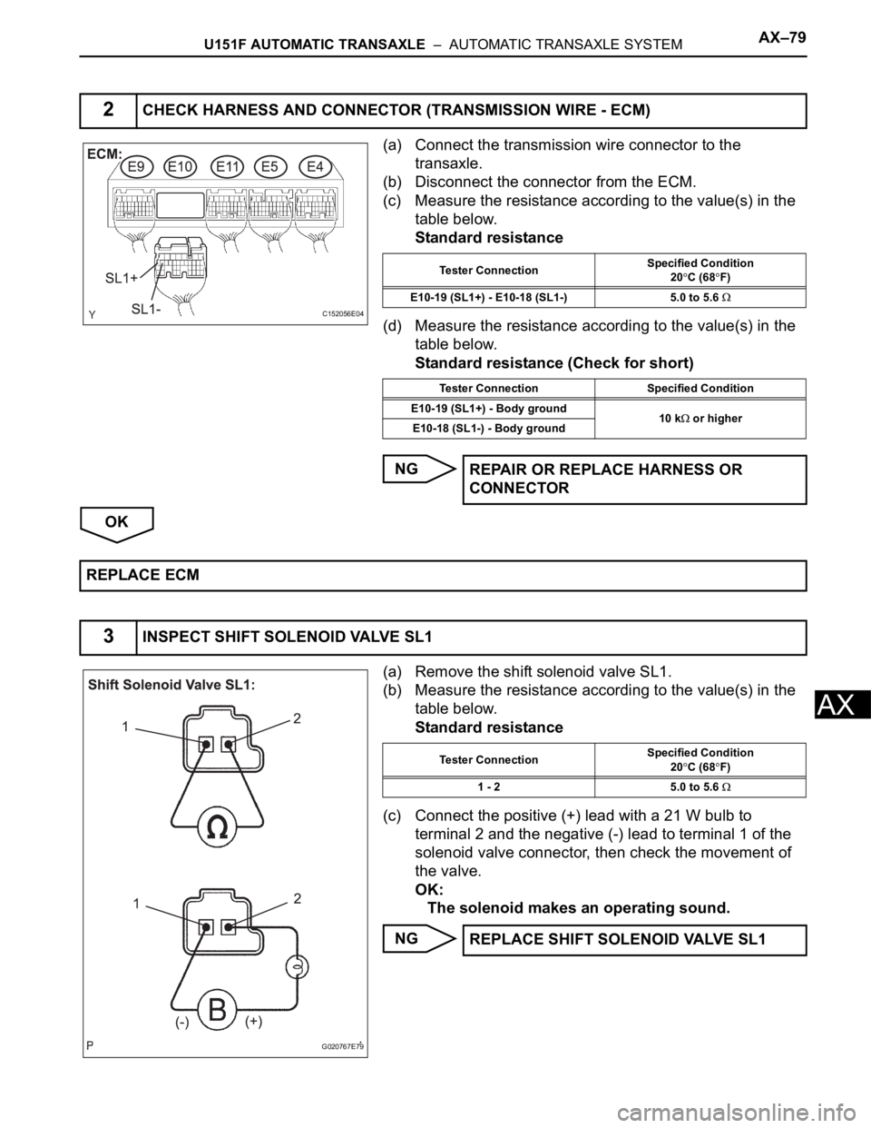
(a) Connect the transmission wire connector to the
transaxle.
(b) Disconnect the connector from the ECM.
(c) Measure the resistance according to the value(s) in the
table below.
Standard resistance
(d) Measure the resistance according to the value(s) in the
table below.
Standard resistance (Check for short)
NG
OK
(a) Remove the shift solenoid valve SL1.
(b) Measure the resistance according to the value(s) in the
table below.
Standard resistance
(c) Connect the positive (+) lead with a 21 W bulb to
terminal 2 and the negative (-) lead to terminal 1 of the
solenoid valve connector, then check the movement of
the valve.
OK:
The solenoid makes an operating sound.
NG
2CHECK HARNESS AND CONNECTOR (TRANSMISSION WIRE - ECM)
C152056E04
Tester ConnectionSpecified Condition
20C (68F)
E10-19 (SL1+) - E10-18 (SL1-) 5.0 to 5.6
Tester Connection Specified Condition
E10-19 (SL1+) - Body ground
10 k
or higher
E10-18 (SL1-) - Body ground
REPAIR OR REPLACE HARNESS OR
CONNECTOR
REPLACE ECM
3INSPECT SHIFT SOLENOID VALVE SL1
G020767E79
Tester ConnectionSpecified Condition
20C (68F)
1 - 2 5.0 to 5.6
REPLACE SHIFT SOLENOID VALVE SL1
Page 1768 of 3000
AX–96U151F AUTOMATIC TRANSAXLE – AUTOMATIC TRANSAXLE SYSTEM
AX
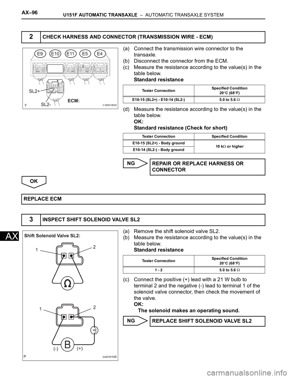
(a) Connect the transmission wire connector to the
transaxle.
(b) Disconnect the connector from the ECM.
(c) Measure the resistance according to the value(s) in the
table below.
Standard resistance
(d) Measure the resistance according to the value(s) in the
table below.
OK:
Standard resistance (Check for short)
NG
OK
(a) Remove the shift solenoid valve SL2.
(b) Measure the resistance according to the value(s) in the
table below.
Standard resistance
(c) Connect the positive (+) lead with a 21 W bulb to
terminal 2 and the negative (-) lead to terminal 1 of the
solenoid valve connector, then check the movement of
the valve.
OK:
The solenoid makes an operating sound.
NG
2CHECK HARNESS AND CONNECTOR (TRANSMISSION WIRE - ECM)
C160512E02
Tester ConnectionSpecified Condition
20C (68F)
E10-15 (SL2+) - E10-14 (SL2-) 5.0 to 5.6
Tester Connection Specified Condition
E10-15 (SL2+) - Body ground
10 k
or higher
E10-14 (SL2-) - Body ground
REPAIR OR REPLACE HARNESS OR
CONNECTOR
REPLACE ECM
3INSPECT SHIFT SOLENOID VALVE SL2
G020767E80
Tester ConnectionSpecified Condition
20C (68F)
1 - 2 5.0 to 5.6
REPLACE SHIFT SOLENOID VALVE SL2
Page 1781 of 3000
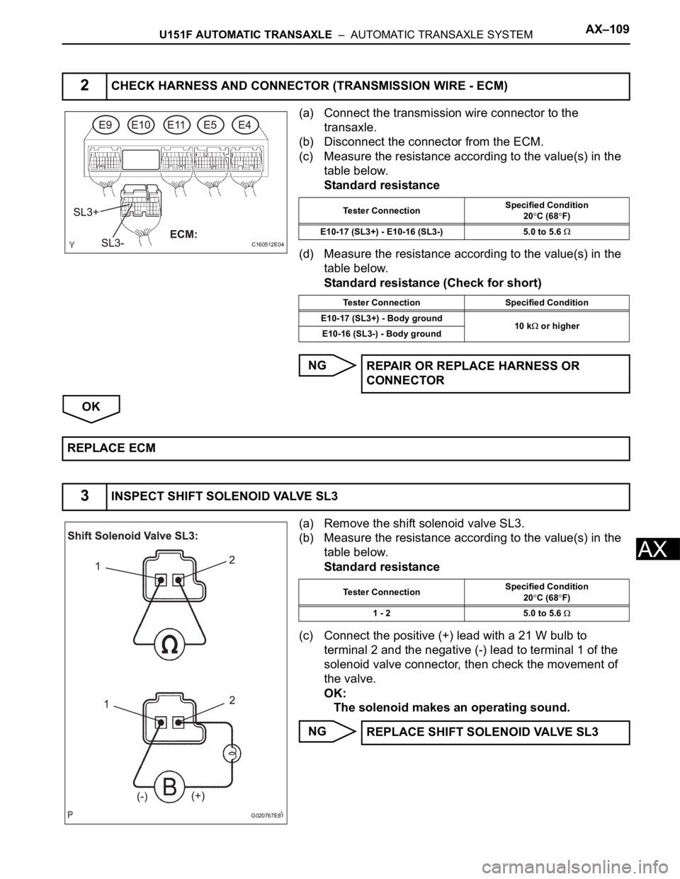
U151F AUTOMATIC TRANSAXLE – AUTOMATIC TRANSAXLE SYSTEMAX–109
AX
(a) Connect the transmission wire connector to the
transaxle.
(b) Disconnect the connector from the ECM.
(c) Measure the resistance according to the value(s) in the
table below.
Standard resistance
(d) Measure the resistance according to the value(s) in the
table below.
Standard resistance (Check for short)
NG
OK
(a) Remove the shift solenoid valve SL3.
(b) Measure the resistance according to the value(s) in the
table below.
Standard resistance
(c) Connect the positive (+) lead with a 21 W bulb to
terminal 2 and the negative (-) lead to terminal 1 of the
solenoid valve connector, then check the movement of
the valve.
OK:
The solenoid makes an operating sound.
NG
2CHECK HARNESS AND CONNECTOR (TRANSMISSION WIRE - ECM)
C160512E04
Tester ConnectionSpecified Condition
20C (68F)
E10-17 (SL3+) - E10-16 (SL3-) 5.0 to 5.6
Tester Connection Specified Condition
E10-17 (SL3+) - Body ground
10 k
or higher
E10-16 (SL3-) - Body ground
REPAIR OR REPLACE HARNESS OR
CONNECTOR
REPLACE ECM
3INSPECT SHIFT SOLENOID VALVE SL3
G020767E81
Tester ConnectionSpecified Condition
20C (68F)
1 - 2 5.0 to 5.6
REPLACE SHIFT SOLENOID VALVE SL3
Page 1785 of 3000
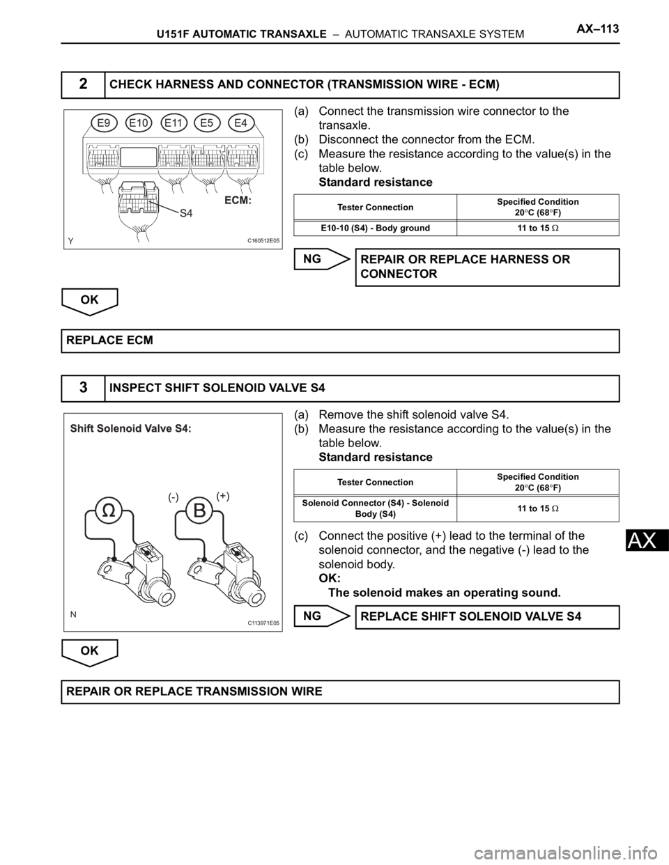
U151F AUTOMATIC TRANSAXLE – AUTOMATIC TRANSAXLE SYSTEMAX–113
AX
(a) Connect the transmission wire connector to the
transaxle.
(b) Disconnect the connector from the ECM.
(c) Measure the resistance according to the value(s) in the
table below.
Standard resistance
NG
OK
(a) Remove the shift solenoid valve S4.
(b) Measure the resistance according to the value(s) in the
table below.
Standard resistance
(c) Connect the positive (+) lead to the terminal of the
solenoid connector, and the negative (-) lead to the
solenoid body.
OK:
The solenoid makes an operating sound.
NG
OK
2CHECK HARNESS AND CONNECTOR (TRANSMISSION WIRE - ECM)
C160512E05
Tester ConnectionSpecified Condition
20C (68F)
E10-10 (S4) - Body ground 11 to 15
REPAIR OR REPLACE HARNESS OR
CONNECTOR
REPLACE ECM
3INSPECT SHIFT SOLENOID VALVE S4
C113971E05
Tester ConnectionSpecified Condition
20C (68F)
Solenoid Connector (S4) - Solenoid
Body (S4)11 to 15
REPLACE SHIFT SOLENOID VALVE S4
REPAIR OR REPLACE TRANSMISSION WIRE
Page 1788 of 3000
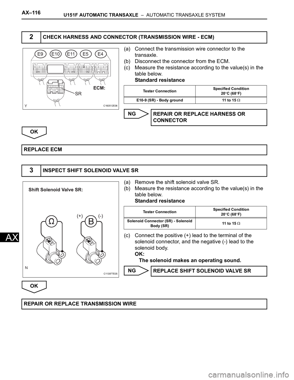
AX–116U151F AUTOMATIC TRANSAXLE – AUTOMATIC TRANSAXLE SYSTEM
AX
(a) Connect the transmission wire connector to the
transaxle.
(b) Disconnect the connector from the ECM.
(c) Measure the resistance according to the value(s) in the
table below.
Standard resistance
NG
OK
(a) Remove the shift solenoid valve SR.
(b) Measure the resistance according to the value(s) in the
table below.
Standard resistance
(c) Connect the positive (+) lead to the terminal of the
solenoid connector, and the negative (-) lead to the
solenoid body.
OK:
The solenoid makes an operating sound.
NG
OK
2CHECK HARNESS AND CONNECTOR (TRANSMISSION WIRE - ECM)
C160512E06
Tester ConnectionSpecified Condition
20C (68F)
E10-9 (SR) - Body ground 11 to 15
REPAIR OR REPLACE HARNESS OR
CONNECTOR
REPLACE ECM
3INSPECT SHIFT SOLENOID VALVE SR
C113977E05
Tester ConnectionSpecified Condition
20C (68F)
Solenoid Connector (SR) - Solenoid
Body (SR)11 to 15
REPLACE SHIFT SOLENOID VALVE SR
REPAIR OR REPLACE TRANSMISSION WIRE