Page 16 of 3000
SS–30SERVICE SPECIFICATIONS – U151E AUTOMATIC TRANSAXLE
SS
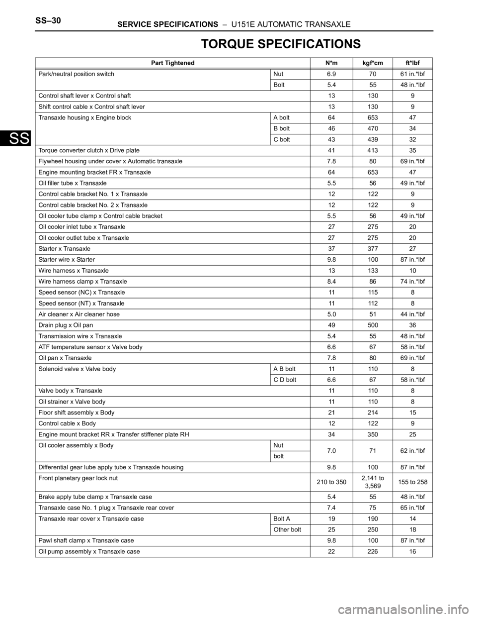
TORQUE SPECIFICATIONS
Part Tightened N*m kgf*cm ft*lbf
Park/neutral position switch Nut 6.9 70 61 in.*lbf
Bolt 5.4 55 48 in.*lbf
Control shaft lever x Control shaft 13 130 9
Shift control cable x Control shaft lever 13 130 9
Transaxle housing x Engine block A bolt 64 653 47
B bolt 46 470 34
C bolt 43 439 32
Torque converter clutch x Drive plate 41 413 35
Flywheel housing under cover x Automatic transaxle 7.8 80 69 in.*lbf
Engine mounting bracket FR x Transaxle 64 653 47
Oil filler tube x Transaxle5.5 56 49 in.*lbf
Control cable bracket No. 1 x Transaxle 12 122 9
Control cable bracket No. 2 x Transaxle 12 122 9
Oil cooler tube clamp x Control cable bracket 5.5 56 49 in.*lbf
Oil cooler inlet tube x Transaxle27 275 20
Oil cooler outlet tube x Transaxle 27 275 20
Starter x Transaxle37 377 27
Starter wire x Starter9.8 100 87 in.*lbf
Wire harness x Transaxle13 133 10
Wire harness clamp x Transaxle8.4 86 74 in.*lbf
Speed sensor (NC) x Transaxle11 11 5 8
Speed sensor (NT) x Transaxle11 11 2 8
Air cleaner x Air cleaner hose5.0 51 44 in.*lbf
Drain plug x Oil pan49 500 36
Transmission wire x Transaxle5.4 55 48 in.*lbf
ATF temperature sensor x Valve body 6.6 67 58 in.*lbf
Oil pan x Transaxle7.8 80 69 in.*lbf
Solenoid valve x Valve body A B bolt 11 110 8
C D bolt 6.6 67 58 in.*lbf
Valve body x Transaxle11 11 0 8
Oil strainer x Valve body11 11 0 8
Floor shift assembly x Body21 214 15
Control cable x Body12 122 9
Engine mount bracket RR x Transfer stiffener plate RH 34 350 25
Oil cooler assembly x Body Nut
7.0 71 62 in.*lbf
bolt
Differential gear lube apply tube x Transaxle housing 9.8 100 87 in.*lbf
Front planetary gear lock nut
210 to 3502,141 to
3,569155 to 258
Brake apply tube clamp x Transaxle case 5.4 55 48 in.*lbf
Transaxle case No. 1 plug x Transaxle rear cover 7.4 75 65 in.*lbf
Transaxle rear cover x Transaxle case Bolt A 19 190 14
Other bolt 25 250 18
Pawl shaft clamp x Transaxle case 9.8 100 87 in.*lbf
Oil pump assembly x Transaxle case 22 226 16
Page 31 of 3000
EM–322GR-FE ENGINE MECHANICAL – ENGINE ASSEMBLY
EM
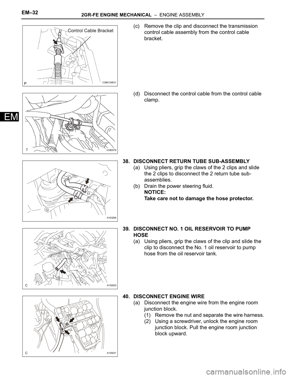
(c) Remove the clip and disconnect the transmission
control cable assembly from the control cable
bracket.
(d) Disconnect the control cable from the control cable
clamp.
38. DISCONNECT RETURN TUBE SUB-ASSEMBLY
(a) Using pliers, grip the claws of the 2 clips and slide
the 2 clips to disconnect the 2 return tube sub-
assemblies.
(b) Drain the power steering fluid.
NOTICE:
Take care not to damage the hose protector.
39. DISCONNECT NO. 1 OIL RESERVOIR TO PUMP
HOSE
(a) Using pliers, grip the claws of the clip and slide the
clip to disconnect the No. 1 oil reservoir to pump
hose from the oil reservoir tank.
40. DISCONNECT ENGINE WIRE
(a) Disconnect the engine wire from the engine room
junction block.
(1) Remove the nut and separate the wire harness.
(2) Using a screwdriver, unlock the engine room
junction block. Pull the engine room junction
block upward.
C089134E01
C090579
A163268
A155029
A155037
Page 90 of 3000
U151E AUTOMATIC TRANSAXLE – AUTOMATIC TRANSAXLE ASSEMBLYAX–163
AX
REMOVAL
1. REMOVE ENGINE ASSEMBLY WITH TRANSAXLE
HINT:
(See page EM-26)
2. REMOVE FRONT DRIVE SHAFT ASSEMBLY LH
HINT:
(See page DS-6)
3. REMOVE FRONT DRIVE SHAFT ASSEMBLY RH
HINT:
(See page DS-6)
4. REMOVE TRANSMISSION CONTROL CABLE CLAMP
(a) Remove the bolt and the transmission control cable
clamp.
5. REMOVE WIRE HARNESS CLAMP
(a) Disconnect the wire harnesses from the clamp.
(b) Remove the 3 bolts and 2 clamps.
6. DISCONNECT WIRE HARNESS
(a) Remove the bolt and disconnect the wire harness.
C083203
D030465
G025456
Page 91 of 3000
AX–164U151E AUTOMATIC TRANSAXLE – AUTOMATIC TRANSAXLE ASSEMBLY
AX
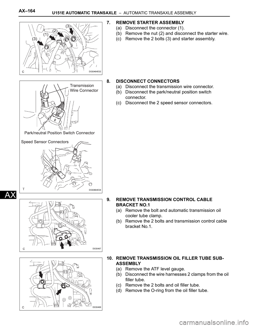
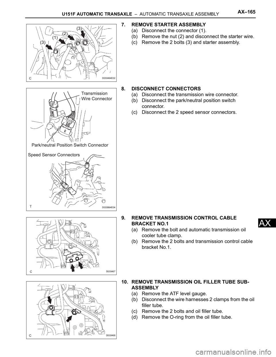
7. REMOVE STARTER ASSEMBLY
(a) Disconnect the connector (1).
(b) Remove the nut (2) and disconnect the starter wire.
(c) Remove the 2 bolts (3) and starter assembly.
8. DISCONNECT CONNECTORS
(a) Disconnect the transmission wire connector.
(b) Disconnect the park/neutral position switch
connector.
(c) Disconnect the 2 speed sensor connectors.
9. REMOVE TRANSMISSION CONTROL CABLE
BRACKET NO.1
(a) Remove the bolt and automatic transmission oil
cooler tube clamp.
(b) Remove the 2 bolts and transmission control cable
bracket No.1.
10. REMOVE TRANSMISSION OIL FILLER TUBE SUB-
ASSEMBLY
(a) Remove the ATF level gauge.
(b) Disconnect the wire harnesses 2 clamps from the oil
filler tube.
(c) Remove the 2 bolts and oil filler tube.
(d) Remove the O-ring from the oil filler tube.
D030464E02
D030864E04
D030467
D030468
Page 95 of 3000
AX–168U151E AUTOMATIC TRANSAXLE – AUTOMATIC TRANSAXLE ASSEMBLY
AX
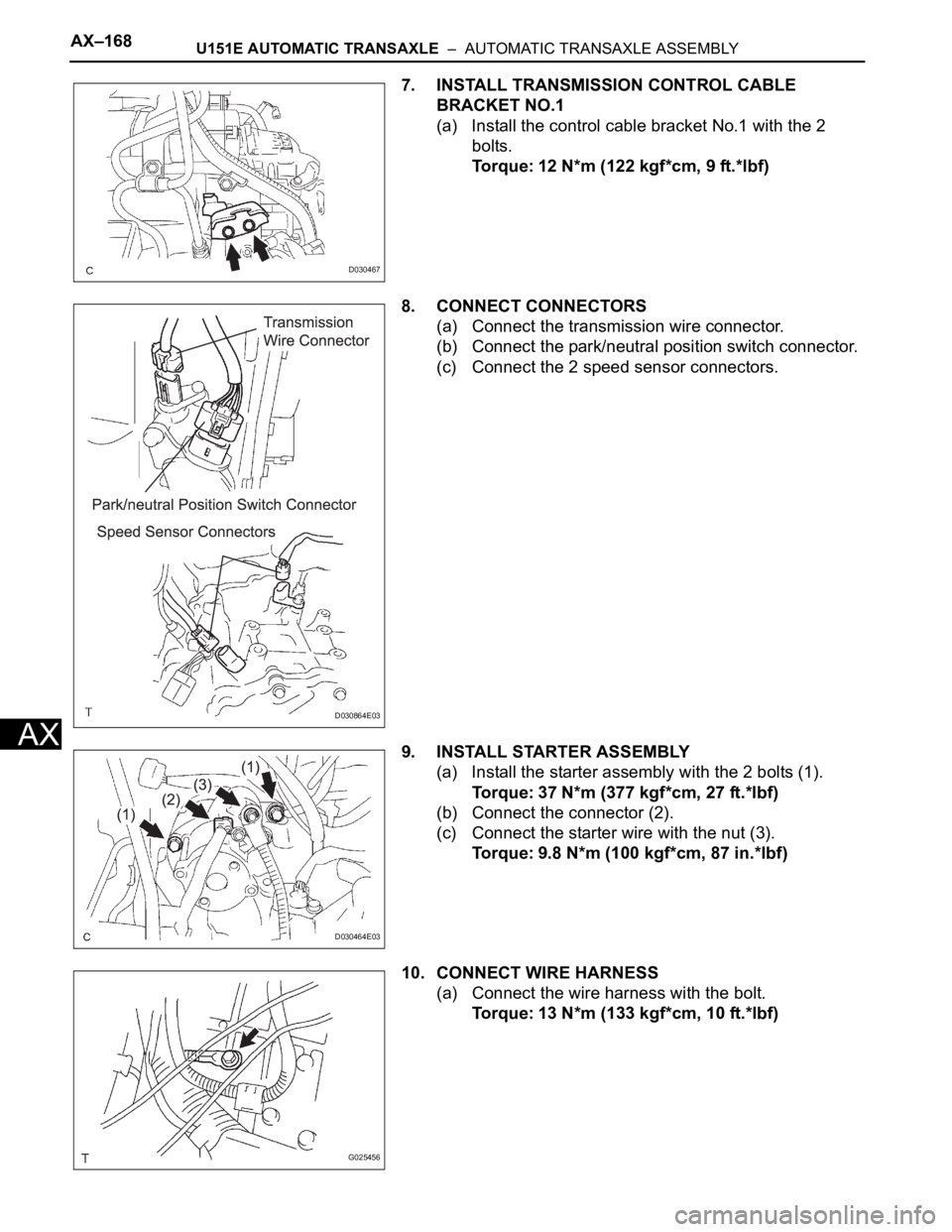
7. INSTALL TRANSMISSION CONTROL CABLE
BRACKET NO.1
(a) Install the control cable bracket No.1 with the 2
bolts.
Torque: 12 N*m (122 kgf*cm, 9 ft.*lbf)
8. CONNECT CONNECTORS
(a) Connect the transmission wire connector.
(b) Connect the park/neutral position switch connector.
(c) Connect the 2 speed sensor connectors.
9. INSTALL STARTER ASSEMBLY
(a) Install the starter assembly with the 2 bolts (1).
Torque: 37 N*m (377 kgf*cm, 27 ft.*lbf)
(b) Connect the connector (2).
(c) Connect the starter wire with the nut (3).
Torque: 9.8 N*m (100 kgf*cm, 87 in.*lbf)
10. CONNECT WIRE HARNESS
(a) Connect the wire harness with the bolt.
Torque: 13 N*m (133 kgf*cm, 10 ft.*lbf)
D030467
D030864E03
D030464E03
G025456
Page 96 of 3000
U151E AUTOMATIC TRANSAXLE – AUTOMATIC TRANSAXLE ASSEMBLYAX–169
AX
11. INSTALL WIRE HARNESS CLAMP
(a) Install the 2 clamps and 3 bolts.
Torque: 8.4 N*m (86 kgf*cm, 74 in.*lbf)
(b) Connect the wire harnesses to the clamps.
12. INSTALL TRANSMISSION CONTROL CABLE CLAMP
(a) Install the transmission control cable clamp with the
bolt.
Torque: 12 N*m (122 kgf*cm, 9 ft.*lbf)
13. INSTALL FRONT DRIVE SHAFT ASSEMBLY LH
HINT:
(See page DS-17)
14. INSTALL FRONT DRIVE SHAFT ASSEMBLY RH
HINT:
(See page DS-17)
15. INSTALL ENGINE ASSEMBLY WITH TRANSAXLE
HINT:
(See page EM-44)
16. RESET MEMORY
HINT:
(See page AX-16)
D030465
C083203
Page 99 of 3000
AX–164U151F AUTOMATIC TRANSAXLE – AUTOMATIC TRANSAXLE ASSEMBLY
AX
REMOVAL
1. REMOVE ENGINE ASSEMBLY WITH TRANSAXLE
HINT:
(See page EM-26)
2. REMOVE FRONT DRIVE SHAFT ASSEMBLY LH
HINT:
(See page DS-6)
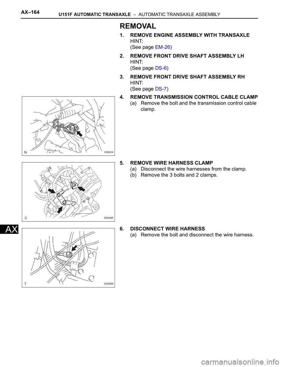
3. REMOVE FRONT DRIVE SHAFT ASSEMBLY RH
HINT:
(See page DS-7)
4. REMOVE TRANSMISSION CONTROL CABLE CLAMP
(a) Remove the bolt and the transmission control cable
clamp.
5. REMOVE WIRE HARNESS CLAMP
(a) Disconnect the wire harnesses from the clamp.
(b) Remove the 3 bolts and 2 clamps.
6. DISCONNECT WIRE HARNESS
(a) Remove the bolt and disconnect the wire harness.
C083203
D030465
G025456
Page 100 of 3000
U151F AUTOMATIC TRANSAXLE – AUTOMATIC TRANSAXLE ASSEMBLYAX–165
AX
7. REMOVE STARTER ASSEMBLY
(a) Disconnect the connector (1).
(b) Remove the nut (2) and disconnect the starter wire.
(c) Remove the 2 bolts (3) and starter assembly.
8. DISCONNECT CONNECTORS
(a) Disconnect the transmission wire connector.
(b) Disconnect the park/neutral position switch
connector.
(c) Disconnect the 2 speed sensor connectors.
9. REMOVE TRANSMISSION CONTROL CABLE
BRACKET NO.1
(a) Remove the bolt and automatic transmission oil
cooler tube clamp.
(b) Remove the 2 bolts and transmission control cable
bracket No.1.
10. REMOVE TRANSMISSION OIL FILLER TUBE SUB-
ASSEMBLY
(a) Remove the ATF level gauge.
(b) Disconnect the wire harnesses 2 clamps from the oil
filler tube.
(c) Remove the 2 bolts and oil filler tube.
(d) Remove the O-ring from the oil filler tube.
D030464E02
D030864E04
D030467
D030468